Transparent Demonstration Rocket
3.2 Construction
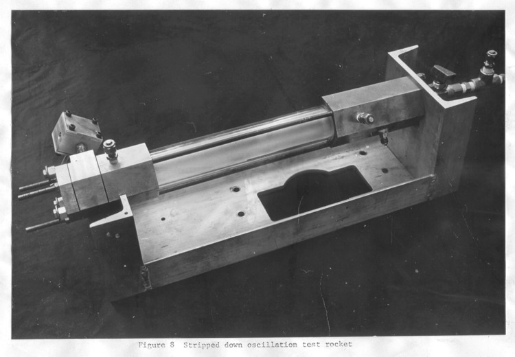
The complete machine, including the vortex valve and its driver, are shown in figure 8 without connecting equipment. The rocket and valve were designed and built with a conscious effort toward simplicity, since I provided the labor. The base is made out of aluminum as is the flow control block pictured in the upper left hand corner. Aluminum was used where temperatures permitted, but even the flow straightener had to be steel after the failure of some aluminum honeycomb. The caps in the picture are for pressure transducer connections, whicle the uncapped fitting is the methane inlet. The methane is injected tangentially as an attempt at better ignition characteristics. No careful testing was done on this, primarily because there were no real ignition problems with pure oxygen. (There are severe problems for air.)
The first sonic orifice is just downstream of the ball valve, with a fitting between it and the ignition block. There is also a sonic orifice in the methane inlet but in this particular case the gas line was so long that the main function of the orifice was to isolate the line from the chamber pressure.
It is not clear from the picture, but the only rigid connection between the base and the rocket body is six bolts around the oxygen inlet. The downstream end rests freely on the support and the different pieces are held together axially by the three steel rods screwed into the ignition block with nuts on the downstream end. The ignition block has been described before except for the spark plug used for the back motors. The spark itself only protrudes into the flow about 1/8 inch.
The plexiglas tubing used for fuel is commercially cast into tubes of maxiumum thickness 1/4 inch. Two concentric tubes are actually shown in the picture. The outer tube serves as a pressure vessel (with a large safety factor) and is sealed on either end by silicone rubber O-rings. The inner tube is the fuel charge and is burned to the extent that the outer tube is reusable.
The next piece downstream is the mixing block. The upstream end is shown in figure 9. Here we see the O-ring on the outside, recessed into the block, and the graphite mixing piece at the center. Graphite was used because it sees the full high temperature flow, which would melt even steel. Also note that the back side of the mixing piece is flat with no rounded edges.