HIGH EFFICIENCY SOLAR FURNACE CORE*
Dr. Stephen C. Bates
Thoughtventions Unlimited LLC
40 Nutmeg Lane
Glastonbury, CT 06033
*Funded by NASA MSFC Contract # NNM05AA41C 2005
Introduction
The Problem. Current solar furnaces exert their technological efforts toward the collection and focusing of solar radiation into a standard furnace. This type of furnace is constrained by the fact that solar power on the earth's surface is limited to about 1 kW/m2; somewhat higher on the moon. Even assuming 100% efficiency, available solar power density then defines a collection area that is needed to achieve a given furnace power input. It is a major problem that current furnaces require large, massive, and expensive area reflectors because these furnaces are not very energy efficient. Another major problem is the need for relatively large light ports into the furnace volume, which imply significant losses out of the same port without improved solar furnace core designs.
The Innovation. The innovation proposed in this program is to develop a high efficiency solar furnace core. This new furnace core will allow much higher furnace temperatures for the same solar energy collection or greatly reduced collection mirror area. Greatly increased efficiency is achieved by coupling vacuum insulation with an inside surface that is a nearly perfect reflector. Specific furnace technology that is available and has been under development at Thoughtventions (TvU) include 1) Low power furnaces; high efficiency heat containment furnaces, 2) High temperature fully and partially transparent furnaces (1200°C), 3) Improved heat radiation shields, 4) Very high temperature furnace technology (2500°C), 5) Vacuum insulation technology, 6) Monitoring technology including viewports and thermocouples, and 7) Furnace design technology. The work described here will define and demonstrate the technology needed for incorporation of these developments into a novel solar furnace that is uniquely suited to in-situ materials processing. The key to being able to demonstrate the feasibility of this technology is the research that has been done at Thoughtventions (TvU) over the past 10 years for NASA [1], [2], [3], [4], [5], [6], [7], [8], [9], [10], [11], [12] and toward commercial products. In-situ materials processing for space exploration are in need of this technology.
The Significance. This program will make in-situ materials processing at elevated temperatures more practical and expand the range of processing parameters that are available using low to moderate power. Moderate power, high temperature, moderate processing volume furnaces will be practical. Low external furnace temperature will allow safe handling and operation of the furnaces in an environment where safety is a necessity. Furthermore, the advances of this program will provide detailed furnace designs and scaling parameters that allow the prediction of power consumption for a low-power furnace of a given size operating at a given temperature.
Technical Objectives
The overall technical objective of this work was to design and demonstrate novel solar vacuum furnace technologies. The specific technical objectives of this program were to:
- Develop superior solar furnace light absorption designs.
- Develop superior heat radiation shielding.
- Test potential solar furnace core designs.
- Assess program feasibility.
- Develop a plan to fabricate and test a Solar Furnace Core Prototype.
Solar Furnace Core Design
Radiation Capture/Containment. A primary problem associated with solar furnaces is that the aperture that is necessary to transfer the solar radiation into the furnace for heating is also the cause of significant heat losses radiated from the furnace back out this aperture. One key solar furnace design element is that the losses through this aperture should be small compared with the incident radiation, and that these losses should not dominate the performance of the furnace. A separate, but also important design characteristic is that the aperture heat losses should be comparable to or smaller than the heat losses through the furnace walls.
The incident solar radiation power density will be very high, not only focused from external mirrors, but also compressed and concentrated using non-imaging optics. It is not to be expected that the radiation will be uniform in power density or in divergence angle throughout the aperture.
The three basic solar furnace design inlet geometries that are possible (shown in Fig. 1) are: 1) The radiation through the aperture is directed at and absorbed by a nearby flat blackbody, 2) The radiation through the aperture is captured in a blackbody cavity, or 3) The radiation through the aperture is reflected around and between walls to a recessed blackbody absorbing wall.
Figure 1. Possible solar furnace heating configurations.
In terms of the energy emitted back out of the aperture, cases 1 and 2 are the same, assuming that the absorbing blackbody temperature is the same. The difference in these two cases is that the absorbed power density of case 2 is much lower - the solar radiation is spread over a much larger area and therefore can distribute and transfer the power to the crucible much better. In the case of a real furnace, one would expect that the exposed area of case 1 would be at a higher temperature than the larger area of case 2 (harder to transfer the heat away), so that case 2 would have significantly lower radiation losses back out the aperture. Unfortunately, the volume utilization of case 2 is very poor, making it also an unattractive candidate for a real furnace.
For case 3 estimating the level of the reradiated power is more difficult. If the walls are highly reflective and sloped properly, essentially all of the radiation passing through the aperture is transmitted to the blackbody behind the reflective passage, rather than being reflected back out the aperture. A detailed ray-tracing was performed to explore the various relevant geometries with the goal of minimizing the amount of energy reradiated out of the aperture.
A computer ray tracing program was used to investigate what kind of furnace Inlet geometry captures the most solar radiation. First, the input radiation was modeled as shown in Figure 2a, where it is assumed that a non-imaging light concentrator is used to bring the maximum amount of light to the aperture, simultaneously increasing the output spread of the light as an inherent aspect of the concentration process.
A computer ray tracing program was used to investigate what kind of furnace Inlet geometry captures the most solar radiation. First, the input radiation was modeled as shown in Figure 2a, where it is assumed that a non-imaging light concentrator is used to bring the maximum amount of light to the aperture, simultaneously increasing the output spread of the light as an inherent aspect of the concentration process.
As ray tracing was begun it was noticed that if the walls of the outer shell and the furnace core were angled and parallel as shown in Fig. 2b, the ray angles of the incoming radiation would be preserved, and the light would be transmitted from the inlet to the absorbing furnace core without losses for perfectly reflecting walls. This is not true for either converging or diverging walls - in these cases some light is reflected back out the inlet aperture.
Figure 2. Solar furnace inlet geometries. a. Input light spread, b. Furnace inlet light channel channeling geometry.
The next question addressed was the determination of the optimum angle, a, setback distance, s, and absorbing wall separation, h. That there must be an optimum, given the practicalities of the problem, can be readily explained. For instance in the case of the angle, a, if a is 0 degrees, quite a bit of radiation is reflected back out the aperture off the right angle wall at the end of the passage. If a is 90 degrees, there is no volume for the furnace; there must be an intermediate optimum. In the case of the separation distance, s, if s is 0, there will be many reflections off the walls and consequent losses for real, partially absorbing surfaces; if s is large, volume use is very inefficient. The optimization of these parameters involves many different aspects of the overall practical engineering design.
Rough optimization suggests a setback distance equal to the aperture radius, an angle, a, of 45 degrees, and a wall separation equal to the aperture diameter.
Next, the issue of light escaping back out the aperture can be addressed. The reference case is a black body at the furnace temperature that radiates back out the input aperture. In the case of the furnace geometry of Fig. 2b, the surfaces that face the aperture are highly reflecting, so that very little radiation is emitted directly from these surfaces. The primary question is what radiation is reflected out of the aperture from the recessed furnace absorbing (and emitting) body. The area at the edge of the absorbing furnace body is much larger than that of the input aperture, but the view factor from the radiating surface is also greatly reduced.
Again, this problem appears too complex to be addressed here. It seems probable that there is some closely related analytical solution that is available from the literature on radiation heat transfer. Certainly the limiting case is that of a blackbody emitting at the temperature of the furnace with an area of the input aperture. Since the furnace temperature is small compared with the effective blackbody temperature of the solar radiation coming through the input aperture, and a small amount of the input radiation is reflected back out the aperture, it seems probable that aperture losses will be small with this design. This conclusion must be verified by future experiments.
As a Thoughtventions product Dr. Bates has been developing a new vacuum furnace concurrent with this program. This furnace has used radiant heat shields similar to those used in the furnace studies described here to minimize power used and component heating. The constraints of the furnace are such that some radiant heat escapes through the vacuum pumping port. This lost heat must be minimized through optimal placement of the radiation shields. The physical problem is to balance the need for unobstructed passages for vacuum pumping, and blocked passages to contain radiant heat losses.
This problem is related to the use of chevrons in vacuum systems to either prevent oil from backstreaming into the vacuum chamber or to condense out vapor before it can foul the vacuum pump. Chevrons provide large-area labyrinthine passages to block direct access to the pump. Minimizing radiation heat losses will be shown to be a somewhat different problem, however.
A number of geometries were examined to determine the optimum. One aspect of the problem is that the radiation must be reflected back into the furnace, rather than simply blocked. Some of the better geometries are shown in Fig. 3. The furnace volume is at the top, with the hot furnace core on the right, and the reflective furnace boundary on the left. The passage area that is needed is defined by the degree of pumping that will result in a vacuum level in the space around the furnace that is sufficient to eliminate convective heat transfer. The needed pumping speed is thus also determined by the materials, geometry, and detailed fabrication of the furnace. Given a specific furnace, the effective pumping aperture defined by h is defined. One can make a labyrinthine passage of reflectors behind h, but this requires that h be larger to achieve the same pumping, and the larger initial h allows larger radiation losses. If one attempts to create some geometry that reflects back out the radiation entering through h, one finds that most of the radiation cannot be reflected back out without blocking the passage unacceptably. The problem then becomes one of placing the position of h to minimize its apparent aperture in collecting radiation from the hot surface.
Figure 3. Furnace shield and pumping geometries that maximize reflected radiation back to the furnace volume.
In Fig. 3, three different geometries are shown, together with the light that passes through the aperture from an arbitrary point A on the hot surface. One can move h toward (1) or away (2) from the inner hot wall, and one can tilt (2) & (3) the aperture. Case (1) has a smaller accepted angle of radiation reflected off the cool wall, but loses direct light at shallow angle. The advantage of this configuration is that the shallow angle radiation is typically significantly less intense for real systems. As point A moves away from the bottom, the angles decrease for Case (1), but increase to some maximum for (2) & (3). Based on the explorations that led to the geometries of Fig. 3, it is not clear if there is some optimum geometry; it seems to be more important to minimize h by optimizing both vacuum pumping and furnace materials.
Materials Emissivity Research
Experiments performed at Thoughtventions to improve low power performance and correlate radiant power losses with different radiant heat shielding materials have demonstrated the importance of knowledge of actual materials emissivity, rather than laboratory measurements under controlled conditions. Clearly these measurements can provide guidelines for optimal materials, but other factors, such as cost and surface changes due to environmental effects can have major effects on the practical performance of these materials.
Material Emissivity. Emissivity data from a variety of sources was surveyed to determine what material is the best heat reflector. The most obvious and primary source was the American Institute of Physics Handbook [13].
This handbook provides reliable data from original sources. There are two types of data in this Handbook; for the first type of data reflectivity is calculated from the index of refraction, n, and extinction, k, values, whereas the second type of data results from experimental measurements. All of the data from the Handbook on Gold and Silver was assembled for direct comparison of values and variations between sources. Table 1 shows the calculated (c) and experimental (e) values for gold (Au), and Table 2 shows the values for silver. The accuracy of the data is not specified, although the experimental data is presented to three decimal places, and the calculation data sometimes four fractional decimal places - 0.1% and 0.01%, suggesting accuracy to half the value of the final digit. Original references for the data are given, and vary in date from 1910 to the 1960's. It is interesting to note that the experimental values are almost always higher than the calculated values, but in general agreement.
Table 1. Calculated (c) and experimental (e) values for the emissivity of gold (Au).
Experimentally, one would expect significant changes in instrumentation and its accuracy to have occurred over this period, as well as major improvements in the 50 to 100 years since each paper. One would also expect there to have been major improvements in sources of material with high purity and in supplied surface finish, both of which factors can strongly affect the value of reflectivity. Experimental data are given to 0.1%, and experiments that provide a 0.1% accuracy are generally very difficult to do, except in certain cases where the parameter can be measured using a technique of exceptional accuracy - which is not the case for reflectivity measurements.
The accuracy of the reflectivity measurements is a critical issue for this program; what is important for minimizing radiant heat loss from a furnace is minimizing the absorption of the heat radiation by the outer container. Although a reflection level between 98% to 99% is almost total reflection, this translates into between 1% and 2% absorption. This may not seem like a lot, but if a furnace container operating at 1% absorption with an associated input power level has its surface contaminated such that absorption is changed to 2%, the new power demand is doubled. Thus, in terms of reflectivity measurements, an accuracy of 0.1% is almost a necessity.
There is significant dispersion in the calculated reflectivities. For instance, for crystalline gold, one source gives a reflectivity of 98.1%, while another gives 96.2% at 1 micron wavelength; at 9 microns wavelength reflectivities of 99.0, 99.0, and 98.3% are given. For Silver at 2 microns, reflectivities of 98.2, 98.55, and 99.1% are given. It is interesting to note that variations in the reflectivity occur in the wavelength region that is much more sensitive to the degree of polish of the surface. Experimental data is given by only from only one source; it is not clear what dispersion there is in experimental data. It is not clear whether detailed reflectivity measurements have been made on today's superpolished surfaces. One would hope so, but such measurements may be proprietary.
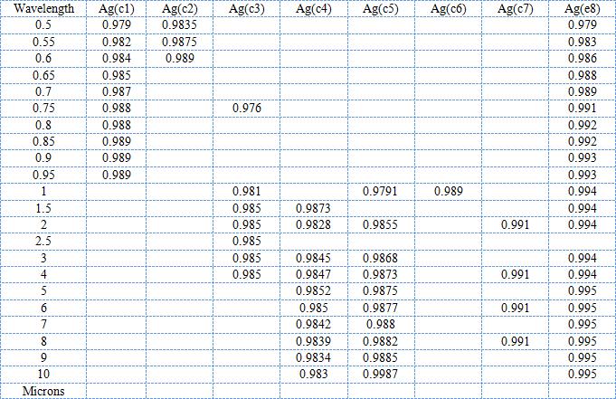
Table 2. Calculated (c) and experimental (e) values for the emissivity of silver (Ag).
Overall, these results imply that silver is a significantly better radiation heat shielding material than gold. The difference is small and perhaps insignificant for low temperature heat shielding where the radiation is concentrated in the mid and far infrared, but large in the high temperature region where there is more visible radiation from the hot object.
To put this in a practical perspective, accepting the experimental values as accurate, at 1 micron wavelength, the normal absorptivity of gold is 1.4%, whereas that for silver is 0.6%, a factor of over 2 in heat absorption. In terms of heat radiation, the fraction of power radiated at wavelengths less than 1 micron is less than 5% for temperatures below about 1600°C, but the absolute power radiated in this wavelength band is 3.5 W/cm2 out of 70 W/cm2. These numbers may not seem large, but a 1600°C cubic blackbody hot zone only 1 foot on a side radiates over a surface of 5400 cm2 with a total power of almost 380 kW. High efficiency radiation shields are a necessity to maintain reasonable power levels to drive high temperature furnaces. At this temperature and volume, shields with emissivity 99.0% absorb 3.8 kW; those with 98% absorb 7.6 kW - a major difference.
Practical Emissivities. The experimental work has shown the importance of practical emissivities. The reflectivity data shown in Table 1 and 2 may be accurate as calculated or measured, but this data may not correctly represent the experimental performance of a material's heat reflectivity. Variations from the Handbook data occur as a result of fundamental material and measurement differences as well as environmental effects. Thoughtventions's work strongly implies that it is much more important to examine and elucidate real surface emissivities and what controls them in a furnace environment than it is to study surface emissivities in a clean, well controlled, laboratory environment.
Real effects that control the effective emissivities in furnaces are many. Some of these effects include contamination, materials bulk and surface properties change with temperature, surface finish, and dependence on the wavelength and incidence angle of the impinging heat radiation.
In terms of fundamental material properties, low level impurities can greatly affect reflectivity, especially if they are concentrated at the surface where the reflection takes place. The reduction of reflectivity through the formation of oxide or ad(& ab)sorbed layers on surfaces is the most well known case of this phenomenon. The effect of low-level impurities in the bulk material is much less well understood and documented. It must be emphasized that the only material of importance as a reflector is that at the surface, as defined by the solid/gas boundary and the skin depth of the radiation interaction with the surface.
An important related question is prediction of the reflectivity of alloys. Both silver and gold are precious materials with poor structural properties. This means that shields made of these materials are not desirable as stand-alone shield materials. Copper, however is almost as good a shielding material that can be used to both reduce cost and increase strength, advantages both for less costly and more convenient commercial development, and as an easy material to use for multiple furnace experiments with different configurations. Thus sterling silver has been used extensively in Thoughtventions's commercial products and as a shield material in this program. It forms a convenient, moderate cost baseline for further development, but it needs more detailed performance measurement than possible in this program.
Bulk and surface material changes with temperature are clearly important. Measured emissivities often vary strongly with temperature, almost always increasing with temperature. This is a practical measurement, however, and it includes a number of effects. One major effect is oxidation of surfaces; most metal oxides usually have high emissivities, and oxidation starts at varying temperatures for different materials and proceeds at different rates as a function of temperature. Certainly materials change color with temperature, but it is not clear how this correlates with emissivity. Common materials also recrystallize at higher temperatures, although, again it is not clear how this affects thermal emissivity. These effects need to be investigated in more detail. Temperature driven increases in emissivity imply that the reflective surfaces be kept at as low a temperature as convenient - not as low as possible. The optimum temperature will be determined as an engineering and economic tradeoff.
The primary fundamental measurement difference between the table data and real surface performance is the incidence of the reflected radiation. Most measurements are performed for normal incidence radiation, whereas heat radiation involves primarily non-normal radiation. Non-normal reflectivity tends to be reduced relative to normal incidence radiation.
Surface Finish. Effective emissivities change with surface finish if the surface is not polished well enough. Probably the surface roughness needs to be significantly less than the wavelength of the heat radiation. This requirement is one that is strongly temperature dependent, since the wavelength of maximum radiant heat emission for a blackbody changes by more than two orders of magnitude from room temperature to high furnace temperatures. IT is easy to fabricate a surface that is smooth relative to 100 micron wavelengths, but much more effort (and cost) is required to obtain a surface that is smooth relative to the 600 nm peak for visible light generated by a high temperature filament. Experiments were limited to furnace temperatures around 600°C, where the peak emitted radiation is approximately 3.3 microns, and all of the radiation has a wavelength longer than 1 micron.
Generating smooth surfaces is more complicated than commonly recognized. The simplest gauge of reflectivity is whether the surface forms a good visual mirror. Surfaces that are extremely smooth can also be poor visual mirrors, not because they do not reflect light, but because their surfaces undulate on longer length scales while being smooth on the finest length scales. Much of the cost of standard polishing is invested in making surfaces both flat and smooth, whereas for radiant heat reflectors, the surfaces need only be smooth.
A major problem in furnace environments is surface contamination. Furnaces necessarily have high temperature surfaces, which many times implies. Low power furnaces must have high temperature surfaces facing highly reflective surfaces. The problem with this combination of surfaces is that unless very carefully prepared, the high temperature surfaces emit materials that condense on and contaminate the cold reflective surfaces. The emitted materials may be as simple as water, hydrocarbons that have not been cleaned off properly, or vapor may be generated by more subtle effects such as minor alloying components or reactants that form from ambient gases, such as oxides.
One key to the fabrication of low power furnaces will be the preservation of the high reflectivity of the enclosing high reflectivity surface by controlling the surface properties of the outer surface of the crucible and by controlling the atmosphere between the surfaces. Vacuum pumping must be sufficient to prevent gas interaction with the hot surface, and remove evaporating materials. The latter of these tasks is more difficult, because once the vacuum level is such that the flow is molecular (no gas collisions) atoms/molecules emitted from the hot surface cannot be prevented from colliding with and depositing on the cold, high reflectivity surface. In fact, this may provide an ultimate furnace lifetime for this type of furnace. This is an issue that requires further investigation.
Heat Shield Experiments. Absorptivity, rather than reflectivity, measurements are the best way to characterize radiant heat shield material candidates. This can either be done indirectly by measuring total power used by the furnace and subtracting heat losses other than radiant absorption, or more directly by measuring the temperature rise of a thermally isolated radiant heat shield.
Absorptivity measurements are more difficult to make, however. In the case of a furnace-like configuration with a low emissivity material built around a central heater, heating times of the shield are long, temperature rises are small, steady state behavior is hard to achieve, and adequate thermal insulation is a challenge. An optimal experimental design is to have the inner surface of the shield have low emissivity and the outer surface have high emissivity. These experiments will be pursued in future work, and are important both for this program and Thoughtventions's commercial furnace development.
Reflective Coatings Produced at Thoughtventions. Thoughtventions has specialized in the internal coating of quartz tubes with gold. These tubes form the outer shell of a 1200°C transparent furnace that Thoughtventions offers for commercial sale. Very thin gold coatings transmit visible radiation while reflecting infrared radiation, thereby allowing visual inspection of heat treating while simultaneously providing excellent insulation. Most companies perform external surface coatings, which are much less effective at radiant heat containment because the underlying quartz absorbs so much of the infrared radiation (longer wavelengths than 5 microns). Thoughtventions is thus well equipped to create gold coated furnace shells for this program. Although silver coatings have not previously been attempted, the apparatus is much the same. Very thin intermediate layers of chromium are used to bond the gold to the quartz.
These coatings have the advantage that they are very smooth as a result of the manufacturing procedure of the quartz - extruded from a melt. This process avoids the need for expensive polishing procedures, and makes the rapid preparation of high quality reflective surfaces possible.
Commercial Metal Radiation Heat Shields. Metallic radiation shield packs are constructed from a variety of metals and alloys. These systems are generally more expensive than carbon-based insulation systems and used only when required by the process. Metallic radiation shields are preferred over carbon-based solutions primarily in cases where moisture control, cleanliness, and carbon contamination issues are present. Other (secondary) factors include more rapid quench rates, faster pump down times and higher achievable vacuum levels.
Shield packs are typically constructed from 3-5 layers of thin sheet (typically 0.03 to 0.06" thick). Both rectangular and cylindrical systems are used, in both horizontal and vertical configurations. These sheets are cut, punched and assembled using traditional sheet metal techniques. The sheets are separated by springs, sheet metal channels formed and bent to shape, or other standoffs constructed of the same material. Assembly of these systems is very complex and must account for the large thermal expansion and contraction experienced during thermal cycling. Ceramic washers and fiber plugs are occasionally used to reduce the size of radiant leaks. These techniques carry risk of providing arc paths as metallic deposits develop on their surfaces during processing.
There are two approaches to improving the generally poor temperature uniformity of these systems. The first is to utilize multiple heating elements to distribute power differentially in an attempt to balance the non-uniform heat flux out of the hot zone. The second approach is to punch holes in the elements in areas where the heat losses are highest, to reduce the effective cross section of the element, increase the resistance, and thereby increase the temperature of the element locally.
The principal metals and alloys used in radiation shields include:
- Tantalum
- Tungsten
- Tungsten/rhenium alloys
- Molybdenum
- Lanthanum-doped molybdebum
- Molybdenum alloys
- Nickel-based alloys
This list is prioritized in order of both temperature rating and cost (highest to lowest). The alloys selected for a particular application are based primarily on the temperature rating required.
Tantalum is used in the very specific case of tantalum capacitor production in order to minimize contamination during processing.
Tungsten is used widely in vacuum furnaces with ratings above 1450°C. Embrittlement due to recrystallization occurs once the material is heated to temperatures above its Curie temperature and returned to lower temperatures. Tungsten is extremely expensive and may be viewed as impractical because slight mechanical impacts can cause the total loss of the hot zone.
Molybdenum is used in furnaces operating between 1100 and 1450°C. In addition, molybdenum radiation shields are sometimes used as the outer shield layers in higher temperature systems (behind the tungsten shields) to reduce cost. Molybdenum also suffers from recrystallization although to a slightly lesser degree than tungsten.
Alloying molybdenum with small amounts of lanthanum oxide increases the ductility even after recrystallization. This increases the materials cost and can only be considered in processes that are not susceptible to lanthanum contamination.
Alloying molybdenum with titanium, zirconium and carbon inhibits grain growth at elevated temperatures. This alloy exhibits significantly higher strength and ductility than pure molybdenum at typical vacuum furnace operating temperatures. However, it has a lower maximum operating temperature of approximately 1300°C.
For systems rated below approximately 1100°C, nickel-based alloys are often used for radiation shielding due to their inherently lower cost and higher ductility. In addition, nickel alloy radiation shields are sometimes used as the outer shield layers in higher temperature systems (behind the molybdenum shields) to reduce cost.
Solar Furnace Core Fabrication and Testing
An earlier NASA MSFC SBIR Phase 1 program developed furnace fabrication techniques that led to an experimental demonstration of a moderate temperature, very low power furnace. Specifically, a small tube furnace was operated at 600°C using only 75 W of power. This high efficiency was achieved by using vacuum insulation, minimal conductive connections, and an outer shell that reflected almost all of the heat radiation coming from the furnace core back into the core. All of these characteristics, as well as the overall design, are well suited for a lunar materials processing solar furnace.
Since this original program, major progress has been made at Thoughtventions both in terms of facilities, facilities capabilities, and in terms of the understanding of the problems of designing and building furnaces.
A variety of furnace advances at Thoughtventions have been incorporated into the present project: 1) Research and development of highly reflective coatings, coating techniques, and pure materials, 2) Research and development of furnace fabrication techniques, 3) Vacuum facilities at Thoughtventions, 4) Improved furnace diagnostics and measurement techniques, and 5) Greatly improved understanding of high temperature furnace design and materials properties. These advances led to the definition of an evolving series of experiments for this program designed to develop both an experimentally demonstrated improved solar furnace core, and a quantitative understanding of the effects contributing to the improved design.
The baseline experiment of Dr. Bates' previous successful low power furnace project is shown in Fig 4. This furnace was used in mid-1999 and remained in open air storage (disassembled) since then. The outer vacuum shell tube of the furnace shown in Fig. 4 was also the outer radiation shield. This was a steel tube that had its ID ground, honed, polished, then electroplated with a gold coating. End radiation losses were reduced by a series of parallel radiation shields. Convection heat loses were eliminated by pumping out the furnace volume through the end ports and around the radiation shields. Conduction heat losses were minimized by eliminating direct solid connections between the furnace core and the furnace shell, only with the exception of the electrical conductors.
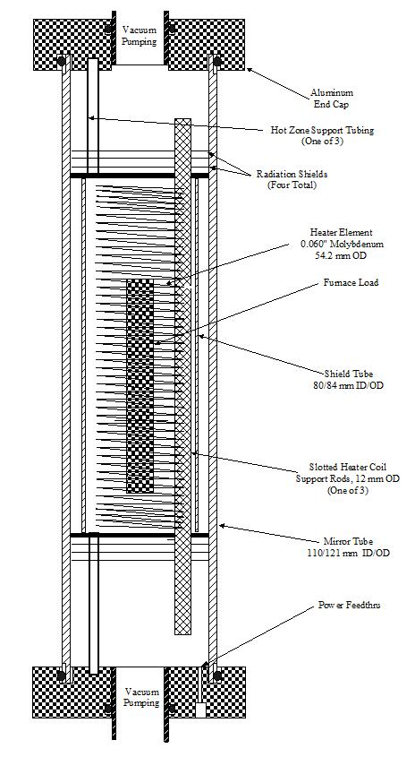
Figure 4. Diagram of Low Power Space Furnace from previous project.
Furnace power was provided by a molybdenum coil supported on grooved quartz rods. A photo of the coil and its support rods is shown in Fig. 5, together with the coil and gold plated shell in Fig 6. As the initial experiment, this coil structure was placed vertically on insulated mounts with current and thermocouple (Type K) feeds from the bottom. A cylindrical reflective shell was then placed around the coil assembly with flat reflective material on the top and bottom of the tubular shell.
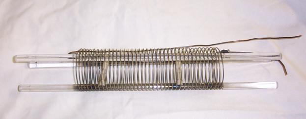
Figure 5. Furnace test core with quartz support rods and molybdenum heater element.
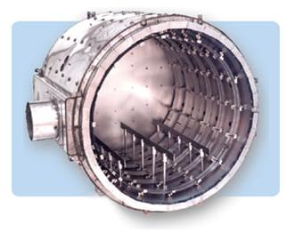
The entire furnace was placed inside a large (50 cm ID, 60 cm high) diffusion-pumped vacuum system. This configuration is similar to operation on the moon (except the pressure is lower on the moon). The importance of this configuration is that it is no longer necessary to custom build the heater element into a vacuum system. Many furnace configurations can thus be tested quickly using a variety of radiation shield materials and configurations.
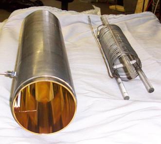
Figure 6. Photograph of gold plated low emissivity outer shell and coil assembly used in testing.
The large vacuum vessel surrounding the test furnaces has another advantage - it eliminates the need to have a large vacuum port in the furnace heat shield to achieve low enough furnace pressure. Without a vacuum port, there is no large aperture through which radiation is lost, so that a complete enclosure can be built. With a surrounding vacuum of 10-6 torr, the gaps in the structure provide sufficient pumping to eliminate convection. This was demonstrated experimentally by a lack of change in heat transfer with pressure.
The experiments for this program also took advantage of reduced conduction losses. Experience at Thoughtventions has shown that rated conductor carrying capacities are much too high for exposed conductors. Small gauge copper is used with safety partly as a result of an understanding of the current carrying capabilities of copper, and partly because the currents are so low for this low power furnace. Small gauge copper means reduced conductive heat losses through the necessary electrical connection. Furthermore, since the coil structure is vertical, the entire structure can rest on insulating pads with small thermal contact area, also reducing conductive heat losses. Previously the furnace core was horizontal, resting on supports securely fastened to the low temperature end caps - significant heat loss paths. For the experiments of this program, a simple variac is used to supply voltage to the furnace element. Using clip-on ammeter and a voltmeter on the input wires of the furnace allows simple power use calculations, with high accuracy. Power measurements for furnace tests were determined by measuring the True RMS current and voltage. The average power is the product of these current and voltage measures. A series of furnace geometries and furnace materials were tested, illustrated in Figure 7. All of the furnaces have some aspects in common. All are heated by AC powered molybdenum wires, all furnaces are operated in a high vacuum environment that eliminates convective heat transfer, and all furnaces are vertical and self-supporting on point contacts to minimize conductive heat transfer. Power input to the furnace is monitored by measuring the electrical current and voltage through the furnace coils. Furnace temperature is monitored by a thermocouple at the center of the furnace in contact with the furnace mass. All of the materials used in the furnace had to withstand temperatures in excess of 600°C, eliminating the possibility of using most common materials. Quartz, alumina ceramic tubing, and stainless steel were the primary materials used in the experiments.
The basic data taken is temperature as a function of input power. The problem is that the power to operate the entire furnace is so low that it takes a long time to reach equilibrium - it takes a long time for the small amount of input power to heat the mass of the furnace and the mass in the furnace. Each data point of temperature at a given power level basically takes a day to equilibrate. For this reason, as few as possible data points were taken to define the power dependence of a particular furnace configuration.
Setup #1 (Fig. 7) uses the same geometry as in the previous SBIR Program, except that the supporting vacuum end caps were removed and the entire apparatus was placed in a large vacuum chamber. The first experiments with Setup #1 were done with the same gold-plated steel tube as the outer shell as in the previous program, and the coil supports rested on insulated pads on the bottom reflector of the furnace. The next experiments were done by replacing the gold-coated tube with a quartz tube that was lined on the inside with sterling silver sheet to determine which material functioned as a better shield.
Analysis of the data from these experiments led to the realization that the heated volume was the important factor, so the heating coil assembly was enclosed in a stainless steel tube, as shown in Setup #2. Results from this experiment were not at all as expected; it was realized that the tube was functioning as a radiation shield, rather than being heated to the core operating temperature. This implied that there must be a large-area solid thermal contact throughout the inside of the furnace.
The needed thermal contact could not be provided in the easiest manner - by adding stainless steel mass to the inner volume of the furnace, since this would short out the coil electrically. The most appropriate material available as a solid thermal connector was a large volume of small, electrically insulating, material that did not outgas (to ruin the non-thermally conducting vacuum) - polishing stones. These were tested to determine if they would tolerate the temperature, and appeared to be vapor free, so they were used to fill up the internal volume of Setup #2, as shown in Setup #3. This attempt failed when it was discovered that the stones were apparently somewhat porous and did emit a lot of gas as they were heated. Simultaneously the coils burned out at a few locations, apparently from contact with the stones. At this point it was realized that it was not going to be practical to maintain the electrical connections through the bottom of a solid apparatus that had to be removed often from the top.
For the next iteration (Setup #4) the heating elements were redesigned. The previous coil design was left over from Thoughtventions's standard furnaces, where the power to operate a furnace had to be generated by a relatively large heated coil area. This need disappears in a low power furnace, such that comparatively thin and short heater wires can be used. Thus six lengths of smaller diameter wire enclosed in ceramic tubes were used to heat the new configuration. The ceramic tubes eliminated the need for insulating filler parts that would provide the thermally conductive link between the coils and the outer stainless steel tube that formed the heated furnace volume.
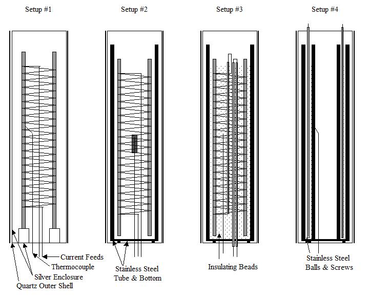
Figure 7. Furnace experiment development series geometries.
Additional Temperature vs. Power experiments were performed without any external shell to determine whether the heat transfer modeling of the system was consistent.
A summary of the configuration details is given below. The power and temperature data generated by the experiments performed to date is given in Table 3. Data from Setups #2 & #3 have not been included because of their lack of relevance.
Table 3
| Date | Setup | Date |
|---|---|---|
| 18 Feb | #1 | Gold plated steel pipe & coil set from previous program, Al foil top & bottom. |
| 23 Feb | #1 | Same as 1) but with sterling silver on the top and bottom |
| 4 Mar | #1 | Outer shell: quartz tube inside lined with sterling silver sheet, same top & bottom. |
| 27 Apr | #4 | Stainless steel inner, outer tubes added, new coil, stainless steel fill between tubes |
| 2 May | #4 | but NO reflective shield |
| 10 May | #4 | Shield cleaned/replaced |
Throughout experimental testing there is a continual concern about the vacuum level inside the radiation shielding. Given the fact that only small holes connect the outer high vacuum with the inner volume, any source of gas from the furnace will lead to higher pressure, and introduce additional heat transfer. New apparatus configurations often generated vapors when heated which led not only to increased convection heat transfer, but led to discoloration of the radiation shielding. Much of this problem was avoided in later operation, when the first heated run was performed without a top lid, providing high pumping speed to remove vapors.
Thoughtventions Vacuum Furnace. The end of the program concentrated on the analysis of experiments and development work on Thoughtventions's 1700°C vacuum furnace.
A schematic of this furnace is shown in Fig. 8. The basic design is a hot zone surrounded by a closed-end alumina tube. Outside this inner tube is a tungsten coil, enclosed by another alumina tube. Both alumina tubes have dual functions. One function is to provide a structural envelope to the hot zone. Another is to isolate the workpiece from the furnace, and to isolate the coils both from the workpiece and the outer heat radiation shields. The coils need to be isolated because tungsten forms oxides that evaporate at intermediates to contaminate surrounding surfaces. The outer alumina tube also has a relatively low emissivity, approaching 0.3 at higher temperatures.
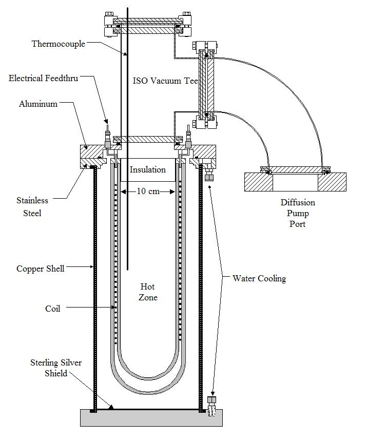
Figure 8. Schematic of Thoughtventions's commercial 1700°C Vacuum Furnace.
The basic design problem of this furnace is the isolation of the high temperatures, and the limitation of the power used by the furnace and transferred to its outer components. These goals are closely related, since the more power the furnace uses, the more power must be dissipated/absorbed in the surrounding structure and atmosphere. Too much absorbed power can lead to structural failure, damaging heat release to the environment, or too great a power demand on either the heating coils or the power supplies. To isolate this furnace core, on the sides and bottom there is an outer shell that has a low emissivity inner Surface, and top insulation is provided by standard ceramic loose fiber insulation. The power radiated by a blackbody at a temperature of 1700°C is 86 W/cm2. A furnace the size of that shown in Fig. 8 has an outer radiating shell of approximately 2000 cm2, leading to a radiated power of about 170 kW, a very large power. The key to Thoughtventions's design approach is identical to the goals of this program: the use of a low emissivity enclosing surface to reject most of this heat back into the furnace core. Since this is an earth-bound vacuum furnace, modifications to the radiant heat transfer enclosure are necessary to be able to achieve the vacuum insulation, to provide structural support for the hot zone, and in this case to be able to evacuate the hot zone. This is the reason that this furnace has only the sides and bottom bounded by low emissivity shields, whereas the top is devoted to vacuum pumping and structural support, insulated by more standard means.
Extensive testing and redesign of this furnace has been done, in an effort to overcome all of the problems associated with this design. The original design used a mullite outer shell with sterling silver sheets molded to the inside of this shell to provide the low emissivity surface. Fracture of the mullite during testing showed that the thermal gradients caused by a combination of heating by the furnace core and water cooling at the base were too large for the mullite to tolerate. Furthermore, there was inadequate thermal contact between the mullite and the shields, causing them to overheat and fail.
Good thermal contact between the shield material and the cool outer shell is critical. Even if the heat input to the shield is small as a result of its low emissivity surface, if the thermal contact of the shield to the outer cool shell is too poor, the shield will slowly heat up, then fail if its temperature rises to the point where the emissivity of the shield increases significantly. The temperature of the shield is determined by the balance between the radiant heat input, determined by the emissivity of the shield and the incident radiant power, and the heat output, determined by the heat conducted to the outer shell. Both the emissivity and the heat conducted are temperature dependent, but whereas the conducted heat is linearly dependent on the temperature difference between the shield and the outer wall, the emissivity of the shield increases slowly with temperature up to some threshold value that depends on the material. The best initial design is to have maximal heat transfer between the wall and the shield to keep the shield temperature low.
A large copper tube was used to replace the mullite, and initial furnace testing was done using the inner surface (polished) of the copper as the low emissivity surface. Copper has an emissivity of approximately 0.1, and this surface was tested in the hopes that it would be good enough in this application. A water-cooled aluminum bottom plate covered with reflective aluminum foil completed the shell. It was found that too much heat was absorbed, and the copper tube was sent out for silver plating and buffing.
Solar Furnace Simulation Experiment. The final experiment of the program was to test a type of solar furnace. The furnace configuration is shown in Fig. 9. Heating is provided only by optical energy - a 150 W filament lamp that is focused into the furnace using an elliptical mirror. The focused light enters the top of the low emissivity enclosure, and is absorbed into the thick-walled stainless steel core. The temperatures of the mirror, the outer wall, and the furnace core were monitored.
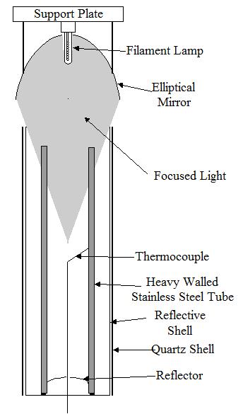
Figure 9. Solar furnace test configuration.
Feasibility Assessment
Analysis of Experimental Data. The experiments performed were designed to both understand the physics underlying the heat transfer in the furnace and to improve furnace performance.
The first major advance of this program has been in understanding the importance and implications of the quantitative heated furnace volume. The statement without qualification from the previous program that a 600°C furnace was operated using a power of 75 Watts was an oversimplification of furnace operation. Given the small workpiece at the center of the furnace, this achievement of a low power furnace, while notable, is misleading if it refers to the size of the furnace rather than the size of the workpiece.
The important parameter is the enclosed volume heated to a given temperature. In the previous program, the heated, enclosed volumes were only the furnace heating element itself, the element support rods, and the relatively small workpiece. This volume was less than 10% of the volume enclosed by the heat radiation shielding. The reason for the importance of enclosed, heated volume, is that the radiated power, and thus the power that must be contained in the furnace by the efficiency of the radiant heat shielding, is determined by the surface area of the heated volume.
The importance of enclosed, heated volume became more and more evident as experiments and analysis proceeded. First, although the elements and outer reflector shell were the same as in the experiment, the power needed to operate the first furnace configuration (Figure 8. Setup #1) was significantly higher. This could have been ascribed to elapsed time dependent deterioration of the gold coating, but it seemed as good as new, and gold should maintain its reflectivity - that is why it is valued in its use for jewelry. Much more likely, and consistent with later data, the increase in power is due to an increase in furnace length from 25 cm, 47 cm in the new configuration, almost doubling the furnace volume.
The experiments of 18 Feb and 23 Feb are nearly identical, due to the minor effect of a change in end shielding material. The sterling silver is better than aluminum, as expected, but the end cap area (162 cm2) is only a bit more than 10% of the tube area (1500 cm2). This data then provides a relatively complete set of power vs. temperature numbers for the case of a gold reflective shield.
The problem with this data is that it is very difficult to use it to extrapolate it to other furnaces. The heated volume is not easily calculated because the relatively large coil supports are at a lower temperature than the coils themselves. Furthermore, since the internal volume is relatively open it is difficult to estimate the reflectivity of the walls because there are so many reflections before the radiation is reabsorbed into the heated surfaces. The next experiment setup was thus modified to have a relatively large heated surface enclosing a volume, such that the reflecting surface was close to the heated surface so that most of the radiation from this surface would undergo only one reflection before being reabsorbed. This is the final Setup (#4) of the reporting period.
Furnace Heating Time Response. At the start of the program it was believed that additional insight into furnace operation could be obtained by examining the time response of furnace heating. Presumably the asymptotic behavior of the temperature response would provide information about furnace efficiency. The data and theoretical curves shown in Figure 10 illustrate the difficulty of this approach. Furnace temperature is plotted as a function of time after the furnace heating has begun, where the furnace is heated at a constant power of 100 W.
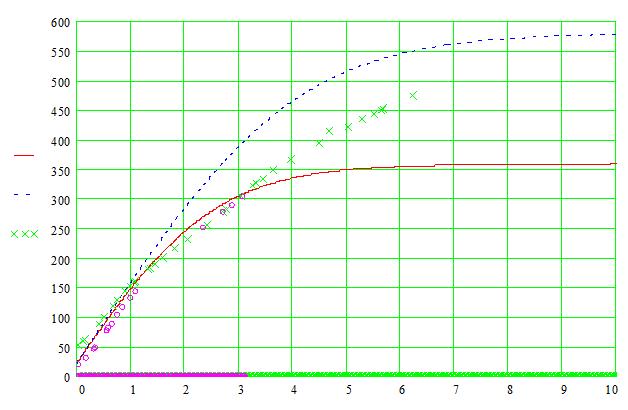
Figure 10. Low power furnace time response. Symbols experimental data, upper curve emissivity of 0.01, lower curve emissivity of 0.03.
One can immediately see that the effective emissivity is somewhere between 0.01 and 0.03, but that neither the slope, nor the asymptotic behavior follows the modeling well enough to deduce detailed emissivity. The initial slope of the line is determined by the heated mass and its specific heat, furnace characteristics that are unimportant for this program. Since, due to the electrical characteristics of the heater elements, it requires constant care and monitoring to maintain constant furnace power throughout a run, this approach was abandoned, and only the asymptotic temperature and power were taken as important data, greatly decreasing the labor required for each run, but limiting useful data points to one per day, due to the slow response of the furnace at these low power levels.
Furnace Power Analysis. Data of power as a function of temperature was taken for the final experimental configuration of the reporting period; Setup #4. This data is given in Table 3. The 27/29 Apr data and the 10 May data measure the performance of the shielded furnace, whereas the 2-3 May data measure the performance of the furnace without shielding.
Figure 11 shows the power (Watts) that the shielded furnace requires to operate at a given temperature. This power is associated with a heated volume of 3110 cm3, the volume enclosed by the outer stainless steel tube. The data follows the blackbody T4 temperature dependence fairly well, demonstrating that other forms of heat transfer are minor, as designed and constructed. The dashed curve is the power prediction based on an emissivity of about 0.025 and an emitting area of about 1440 cm2 - the area of the outer tube of the heated volume of the furnace.
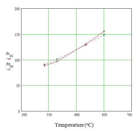
Figure 11. Furnace power (Watts) data. Solid curve, x data points, denote experimental power data; dashed curve, o data points, denote blackbody temperature behavior for an emissivity of 0.025.
Figure 12 shows the power (Watts) that the unshielded heated core of the furnace requires to operate at a given temperature. This power is associated with the same heated volume of 3110 cm3. The data again follows the blackbody T4 temperature dependence fairly well, but of course the temperatures are significantly lower without the outer heat shield. The dashed curve is the power prediction based on an emissivity of about 0.15 and an emitting area of about 1440 cm2 - the area of the outer tube of the heated volume of the furnace. The vacuum chamber wall is reflective except for the windows in the vessel because this vessel has been used for a number of gold plating jobs. This presumably explains why the apparent emissivity is 0.15 rather than closer to 0.5 for discolored stainless steel. This must be verified in future experiments.
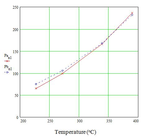
Figure 12. Unshielded furnace power (Watts) data. Solid curve, x data points, denote experimental power data; dashed curve, o data points, denote blackbody temperature behavior for emissivity of 0.15.
Low Power Furnace Scaling Factor. A primary goal of the present program is the development of a scaling factor for high efficiency furnaces that will allow prediction of the power needed to operate a furnace of a given volume at a given temperature. This will also provide a Figure of Merit for high efficiency furnaces, such that a real furnace can be compared with the best that can be done and factors contributing to relative inefficiency can be identified.
Before the power per unit volume can be discussed, furnace geometry must be considered. For a low power furnace with convection eliminated by vacuum and thermal conduction losses minimal, the power emitted by the furnace core volume is proportional to the surface area, the surface emissivity, and T4. Since the total power is determined by the surface area, but the usefulness of the furnace is determined by its volume, the furnace must be designed to obtain the maximum volume for the minimum surface area. The shape that would normally be associated with such an optimization is a sphere, which offers the best case mathematically. Unfortunately spheres are inappropriate for practical furnaces due to the difficulty of fabricating such a shape, and the awkwardness of providing inlet and outlet attachments for this furnace volume. Thus, a cylinder with minimum surface area per unit volume is considered.
For a cylinder the total Surface Area, S = 2πR(R + h), where R is the radius of the cylinder and h is its height. The volume, V, of the cylinder is πR2h. The surface to volume ratio, S/V is,
S/V = 2πR(R + h)/πR2h = 2(R+h)/Rh = 2(1/h + 1/R)
Assuming a volume, Vo, for which the surface area is a minimum, then h = Vo/πR2, and
S/Vo = 2(πR2/Vo + 1/R)
Minimizing surface to volume ratio:
d(S/Vo)/dR = 2(2πR/Vo + 1/R2) = 0 for minimum
and
2πR/Vo = 1/R2, R3 = Vo/2π,
and
R = (Vo/2π)1/3
Calculating the surface to volume ratio:
(S/V)min = 2(π(Vo/2π)2/3/Vo + 1/(Vo/2π)1/3) = 2Vo1/3(π1/3/22/3 + (2π)1/3)
(S/V)min = (2πVo)1/3
If Vo = 1, the R = 0.54, and the cylinder is, as expected, close to a sphere, with a radius close to its height. This provides the relation between surface and volume that allows a volume scaling factor to be developed.
The power, P, per unit volume, V, is this:
P/V = (P/S)/(2πV)1/3 in units of W/m3
P/V = εeffσT4/(1.84V1/3) (1)
Where εeff is the effective emissivity of the furnace system (NOT the heated volume surface), and V is the HEATED volume, NOT the volume of the furnace, which is somewhat larger due to the added volume of the furnace's outer heat reflector.
The power per unit volume thus scales as the furnace temperature to the fourth power, and its volume to the 1/3 power. The experiments of the reporting period allow initial numbers to be assigned. For a volume of 3110 cm3, operating at a temperature of 500°C, a power of 100 W has been demonstrated. Thus
P/V = {100/(1600)}/(1.84)(3110)1/3
= 0.00255 W/cm3
= 2,340 W/m3 at V = 0.00311 m3, and 773 K
Thus a initial volume scaling factor of just over 2 kW/m3, and an initial scaling factor is believed to be:
P/V = 2.34 (V/0.00311)1/3(T/773)4 kW/m3, V in m3, T in K
Thus, for a 1 m3 volume operating at 1000°C, this scaling factor would predict:
P = (2.34)(6.6)(7.35)
P = 113 kW 1 m3, 1000°C
The effective emissivity of the system can be calculated from equation (1) above:
P/V = 2340 W/m3 = (εeff)(5.67 x 10⁻⁸)(773)4/[(1.84)(0.00351/3)]
εeff = (2340)(0.28)/(5.67 x 10-8)(3.57 x 10¹¹) = (0.655)/(20.24)
εeff = 0.032
This is a reasonable conclusion, consistent with the normal emissivities of gold and silver, which are 0.01 or 0.02, depending on many factors, and consistent with the results of Figure 11. Non-normal emissivities are expected to be higher. It is not known what the normal emissivity of sterling silver is.
Radiant Heating Experiment. To confirm that radiant heating of the furnace core is the same as coil heating, the core was heated by a filament lamp focused into the core by an elliptical mirror. The power was fixed at 50 W (to prevent overheating of the lamp and mirror in vacuum) and the furnace core was heated to a temperature of approximately 260°C. This result is consistent with the coil heating results and confirms the solar furnace design principles.
Comments can be made about the detailed comparison between the lamp and coil heating experiments. The coil heating experiments are much more accurate in terms of power balance than the lamp experiments; the lamp power transfer is much less efficient. The reason for this is the inefficiency of converting electrical to optical energy in the lamp, and the large apertures in the system. The largest loss is heat from the filament lamp, this heat is not well transferred to the furnace core.
Prototype Furnace Fabrication. A cross-section schematic of a proposed prototype furnace is shown in Fig. 13. This is a combination solar furnace core and resistively heated tube furnace. The radiant heating port can be replaced to make this a more standard, but very low power furnace. The hot zone is 10 cm in diameter and 30 cm long, bounded radially by closed-end alumina tubes that enclose a tungsten wire heater element mounted on slotted boron nitride coil supports. The radial outer boundary of the furnace is an internally silver-coated copper tube (the mirror tube). Axially the outer boundary of the furnace is a 3 cm thick, rectangular aluminum end cap on each end.
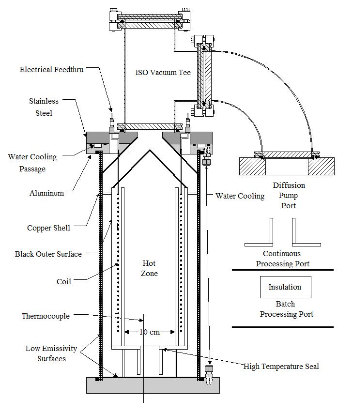
Figure 13. Schematic of Prototype Furnace.
The vacuum envelope is created by O-ring seals in the end caps at the end of the mirror tube, and by O-ring seals at axial ports at the center of the end caps through which vacuum pumping is done. Vacuum seals are also placed around thermocouple and heater element current feedthrus. Vacuum measurement ports are included in each end cap and at one location near the center of the mirror tube. Vacuum pumping is performed by a 10 cm diameter oil diffusion pump backed by a mechanical vacuum pump. Pressure/vacuum is monitored by a convection type gauge. Pumping is done through 8 cm diameter axial ports through an end caps. The central portion of the furnace is pumped around the gap between the mirror tube and the axial radial shield OD, as well as through staggered 1 cm holes (none straight through) in the four axial radiation shields and down the center axis.
Overall Project Feasibility Assessment. Experiments, design, modeling, analysis, and research have combined to demonstrate the feasibility of a high efficiency solar furnace coil. The primary project conclusions supporting feasibility are as follows:
- A reflective solar furnace entry section has been designed to maximize absorbed radiant heat and minimize re-emitted radiant heat. Analysis confirms that this design should be much more efficient than current designs.
- Practical low emissivity radiant heat shields have been developed to minimize radiant heat losses.
- Convective heat losses are made insignificant through vacuum insulation using lunar vacuum.
- Conductive heat losses are minimized through proper design of low thermal conductivity support struts, which can take advantage of the lower lunar gravity.
- Overall furnace power levels are reduced by up to a factor of 3 compared with standard furnace designs, either allowing a large reduction in solar collection area for a given operating temperature, or a much greater operating temperature.
- Thoughtventions's commercial furnaces have demonstrated furnace power minimization designs.
- A practical Prototype has been designed, including all of these advances.
References
1. S. C. Bates, "High Performance Sapphire Windows," SBIR Phase I Final Report, NASA Contract NAS3-26330, (1992).
2. S. C. Bates and L. Liou, "High Performance Sapphire Windows," Technology 2002, NASA Conference, Baltimore, MD, (1992).
3. S. C. Bates, "High Temperature Transparent Furnace Development," SBIR Phase I Final Report, NASA Contract # NAS3-26566, (1994).
4. S. C. Bates, "Controlled Crystal Growth Using Auxiliary Optical Heating and Optical Diagnostics," SBIR Phase I Final Report, NASA Contract NAS8-40546, (1995).
5. S. C. Bates and K. S. Knight, "Auxiliary Optical Heating for Controlled Crystal Growth," J. Crystal Growth, 240, 1-2, 277 (2002).
6. S. C. Bates, "High Temperature Fiber Optic Imaging," SBIR Phase I Final Report, NASA Contract NAS3-26566, (1995).
7. S. C. Bates and R. F. Chang, "High Temperature Fiber Optic Imaging," Fiber and Integrated Optics, 6, 6, 387 (1997).
8. S. C. Bates and R. F. Chang, "High Temperature Fiber Optic Imaging," SPIE Proceedings 2839, SPIE Int. Symp. on Opt. Sci. Eng. and Instrum., (1996).
9. S. C. Bates, "High Temperature Transparent Furnace Development," NASA Contractor Report, NASA CR 202333, (1997).
10. S. C. Bates, K. S. Knight, D.W. Yoel, "High Temperature Transparent Furnace Development," Space Technology and Apps. Intnl. Forum-1998, DOE CONF-980103, Amer. Inst. of Phys., 711 (1998).
11. S. C. Bates, "High Temperature Transparent Furnace Development," SBIR Phase II Final Report, NASA Contract NAS3-27664, (1997).
12. S. C. Bates, "Low Mass, Low Power, Low Cost Space Furnace," SBIR Phase I Final Report, NASA Marshall Space Flight Center, Contract # NAS8-99040, Sept., (1999).
13. D. E. Gray Ed., American Institute of Physics Handbook 3rd Ed., McGraw-Hill, New York, NY, (1973).