Next Generation Transparent Furnace
40 Nutmeg Lane
Glastonbury, CT 06033
ABSTRACT
Novel fabrication techniques are being used to build a next generation transparent furnace. That will significantly lower of the high cost of high temperature transparent furnaces and solve the problem of the high external temperatures of current transparent furnaces. A low power, high temperature prototype furnace is being built that has visual access to the hot zone but operates at a low furnace external temperature. A specially developed insulating furnace wall achieves almost complete heat containment. Full optical access to furnace applications is needed to diagnose the subtleties of high temperature processes and for future applications in process control in space and on earth. Transparent furnaces can be used for research in crystal growth, sintering, metal joining, annealing, high temperature materials properties, and fluid behavior.
The Problem. Most high temperature materials processing conditions are set by general prediction, experience and iteration. Nonintrusive, in-situ optical diagnostics are now being used for research and optimum process control in the presence of complex furnace effects, but these techniques require optical access to the hot zone and workpiece. Small furnace windows or standard transparent furnaces are currently used to provide access for materials processing but both of these options have serious drawbacks. Windows are awkward to add to a furnace, give only limited optical access, and usually disturb the furnace heat distribution. Standard transparent furnaces have a limited operating temperature and have a high enough exterior temperature that operation and safety in space a problem. A transparent furnace with full optical access to furnace applications that is low cost, operates at high temperature, and has a low external temperature is needed for the development of practical materials processing under microgravity conditions in space and for commercial purposes on earth.
The Innovation. The innovation of this work is the use of novel fabrication techniques to build a next generation transparent furnace. A sealed quartz vacuum insulation jacket unit is being built containing a gold coating that reflects infrared heat while transmitting visible light for sample observation. The development of a 1000°C gold coating allows high temperature furnace operation. These characteristics allow the fabrication and operation of a low power, high temperature furnace that has visual access to the hot zone and a low furnace external temperature.
The Program. A low-cost vacuum and thermal radiation containment vessel is being developed that can be used in a high temperature transparent furnace. A high-temperature gold coating will be developed for infrared heat containment, and this coating will be integrated with transparent gold coatings for optical access to furnace operations. These techniques will allow fabrication of a prototype gold-coated transparent furnace tube. Simultaneously, the fabrication techniques that can produce a double-walled quartz vacuum jacket will be used so that convection heat losses will be eliminated from the furnace. A vacuum jacket will be fabricated with a gold-coated outer tube, providing both convection and radiation insulation for the furnace. This insulating jacket will be used to fabricate a prototype transparent furnace that includes standard features such as temperature monitoring and control and sample access. The prototype transparent furnace will be tested for optical, thermal, and energy performance. The feasibility of the new transparent furnace will be assessed in terms of performance and cost, and a plan is being developed to create a near-commercial next-generation prototype transparent furnace that will be a deliverable to NASA.
Why develop a new transparent furnace? The justification for this program is the need for 1) A low cost high temperature transparent furnace, 2) A low external furnace temperature for space handling and safety, 3) Elimination of multiple radiation heat shields, and 4) The capability for low power operation. Thoughtventions has already demonstrated the thermal technology, and seeks to complete the development of this technology.
Background. The background for this work is in the areas of 1) Transparent Furnaces and 2) High Temperature Heat Transfer and is not intended to be comprehensive, but to communicate a limited amount less well known information.
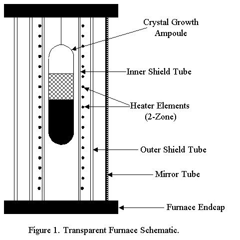
Transparent Furnaces. Transparent furnaces have been used for many years, and are based on a concept first invented and patented at MIT [1]. In a standard earth-based transparent furnace, a thin gold mirror is coated onto the wall of a glass tube that surrounds the furnace hot zone. A typical furnace used for crystal growth is shown schematically in Fig. 1. The mirror coating has the characteristic that it reflects heat radiation, but is semi-transparent at shorter wavelengths. Depending on the details of the coating, approximately 95% of the incident infrared energy is reflected whereas roughly 80% of the visible radiation is transmitted. Over 90% of the total energy incident from a 850°C blackbody is reflected. The thin gold film coating thus provides radiant insulation while simultaneously allowing a clear view of processes occurring at the furnace core. Furnace heating energy is provided by resistance heating elements that are spaced far enough apart to allow good visibility through the elements. A quartz tube is usually located between the heater and mirror to prevent the outgassing heater material from coating the mirror and reducing its effectiveness. A quartz 'muffle' tube mounted between the heater and the workpiece acts as an impurity barrier and reduces hot spots.
The high temperature weaknesses of standard transparent furnaces are in the areas of transparent shell materials and radiation containment coatings. Current technology uses fused silica tubes that sag at high temperatures. The reflective coating on the transparent substrates also have a limited the ability to survive high temperatures. To date, multizone transparent furnaces have been limited to temperature ratings of 1100°C.
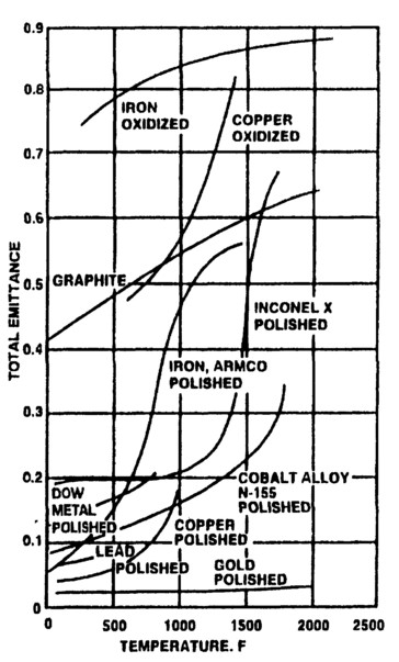
Figure 2. Metal emissivities as a function of surface condition and temperature. [6]
Commercially, transparent furnaces are used primarily for crystal growth. For research they provide critical insights into the details of crystal growth, material processing, high temperature fluid mechanics, biomass energy conversion, and other work. The ability to observe events within the furnace during crystal growth, sintering, metal joining, and annealing, can provide insights that cannot be obtained from traditional post-cooldown sample characterization. In vapor crystal growth on earth, even at pressures where diffusion is the primary transport mechanism, convection has been shown to adversely effect the quality of crystals grown from the vapor phase. The in-situ, non-intrusive observational capability of a transparent furnace leads to the ability to change the growth ampoule temperature and/or temperature profile during processing to obtain superior crystals.
Specific applications involving crystal growth include detection of: 1) Nucleation; if multiple nucleation sites occur, a new solidification process can be started, 2) Melt/solid interface through differences in density and emissivity between the liquid and solid, 3) Surface tension effects as a result of liquid-solid differences. This capability is important for microgravity research), 4) Convection through index of refraction changes with temperature, 5) Internal temperatures through tomography, and 6) A variety of crystal defects, depending on the optical properties of the crystal. Together, these capabilities provide a powerful incentive to use transparent furnace. The incentives are further enhanced when standard optical diagnostics are produced to monitor processes in the furnaces. A case study showing the benefits of transparent furnace use is given by Schunemann and Pollak [2].
High Temperature Heat Transfer. Radiant heat transfer is the dominant mechanism for heat loss at high temperatures (above 1000°C) without flowing or boiling liquids, and without large-area, high thermal conductivity solid contact between the hot zone and the environment. Radiation heat loss is defined by the Planck function as it describes blackbody radiation - a body that absorbs all incoming radiation. The total radiated power by a blackbody at temperature, T, is given by the familiar Stefan-Boltzmann function:
Wtotal(T) = 5.679 x 10⁻¹² T4 W/cm2
The dependence of the radiated power on T4 is what accounts for the dominance of radiation at high temperatures. For real materials the total radiated power differs from that of a blackbody by the total emittance, ε t, such that Wreal(T) = ε t(T)Wblackbody(T). Total emittances are integrals over wavelength of detailed emissivities that are also wavelength dependent. Total emittances can be quiet low, but also can depend strongly on temperature, usually increasing with temperature. Examples of commonly used materials are shown in Fig. 2 [3].
Heat transfer as a result of convection and conduction can be estimated by using a thermal resistance versus temperature concept where Rthermal = Δ T/q, where Δ T is the temperature difference across the resistance path and q is the heat flux entering the resistance. A contact coefficient of heat transfer, hs, is R/A, where A is the contact area. For a wall, h = k/t, where k is the thermal conductivity, and t is the wall thickness. Orders of magnitude for h in W/m2-K are 1) Gases in natural convection: 5-29, 2) Flowing gases: 11-290, and flowing liquids (non-metallic): 170-5700.
Convection can be eliminated by using vacuum enclosures. Conduction can be reduced by limiting contact area and using materials of low thermal conductivity (glass). Thermal radiation can be reduced by using materials with low thermal emissivity.
Technical Program
Transparent furnaces use coatings on quartz or glass (Pyrex) that reflect the infrared heat radiation while simultaneously transmitting enough visible light from the furnace core so that a workpiece undergoing thermal processing can be directly observed. Most transparent furnaces rely on very thin coatings of gold on the exterior of an outer tube to provide this response to radiation. Most metals reflect in the infrared and absorb short wavelength radiation, but a very thin coating that gives transmission of visible light is peculiar to gold. The reflectivity of gold is shown in Fig. 3 [4].
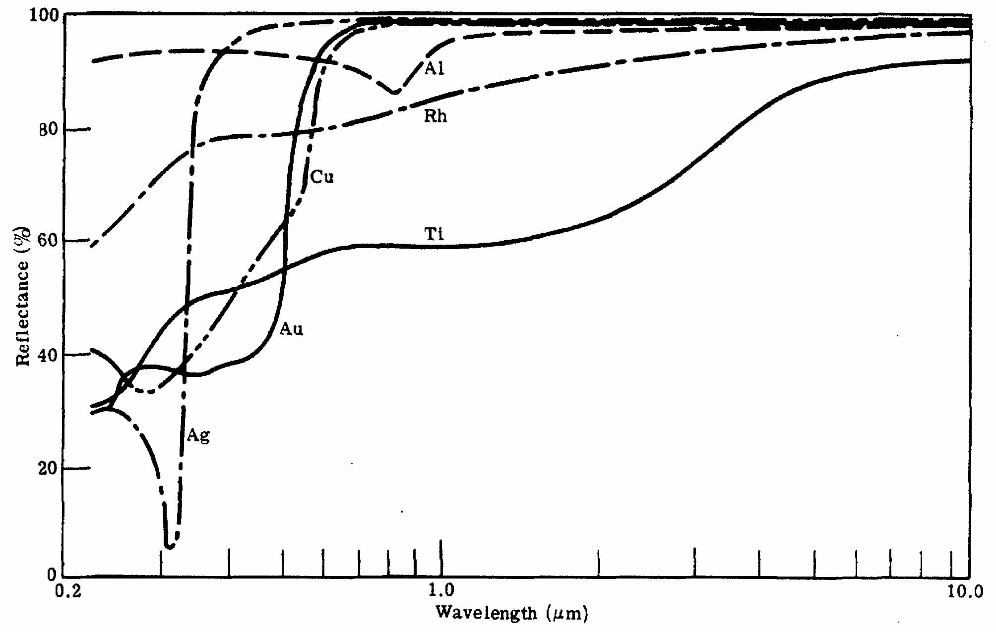
Figure 3. The reflectance of various films of silver, gold, aluminum, copper, rhodium and titanium. [7]
Many other materials have been used for what are now known as heat reflective windows. Both high visible transmission and near perfect broadband IR reflection have been achieved, driven by the mass market for solar windows. Unfortunately, these materials cannot survive temperatures above a few hundred °C and are thus not candidates for application to transparent furnaces. Gold is thus the preferable coating material for this program as a result of its ease of application, long use, and well developed technology.
Gold has a nominal emissivity of 2% at 1 µ m wavelength, dropping to 1% at 8 µ m. For radiation calculations the 1/ε gold factor of 50 dominates most other effects. If the emissivity of the gold coating rises as a result of surface contamination, absorbed power/power used in the furnace increases by 50%. It is therefore critical to use the lowest possible emissivity material (high purity gold) and to prevent it from being contaminated. Any hole in the furnace has an emissivity of 1, so that the area of the hole represents losses equivalent to 50 times what that area would have with a gold-coated surface, assuming an emissivity of 2%. Such holes/apertures must obviously be minimized to minimize power losses. Gold also has the advantage of being relatively inert. It is, of course, widely used as a radiative insulation coating on materials. Gold is not used in commercial furnaces, presumably as a result of a combination of lack of contamination control and cost. Gold-coated mirrors are the most common type of IR mirror in general use.
Angle of Incidence. The reflectivities discussed here are given for normal reflection, which is the common practice. The radiation in a furnace is incident at all angles, although very little is probably present at the outer tube surface at very high angles of incidence as a result of the curvature of the surface. Data on reflectivity vs. incidence angle [5] indicate that the reflectivity of gold begins to be affected at angles on the order of 60 degrees, and drops rapidly for angles greater than 80 degrees. It is not clear how this will affect furnace radiation containment; probably Phase 2 experiments will be required provide information on this issue.
Mirror Tube Coatings. Another common feature of transparent furnaces is that the entire furnace outer shell is a gold-coated quartz or glass tube. Although furnace transparency is usually only required at the center of the furnace, all furnaces have an entire, uniform outer shell because it is cheaper to coat the entire tube than it is to put in a short transparent section and a longer fully opaque and reflective section.
Surface Protection. A key factor in fabricating and using low emissivity radiation shields in furnace is that the surface properties must be maintained during furnace operation. The most common problem encountered when using gold mirror tubes in furnaces is vapor deposition contamination of the gold. One solution to this problem is to use a quartz shield. If the inner quartz shell gets very hot, quartz will evaporate from the inner shell and form a thin transparent layer on the mirror and not degrade its performance. Any coatings need to be at least as thick as the wavelength of light to have significant absorption, so coatings less than 0.1 microns will not have significant effects. Since visible light has significantly shorter wavelength than the heat radiation, probably the existence of visible overcoatings is a good diagnostic for whether the gold has become ineffective after being coated. Overcoating will be avoided by using a double tube quartz jacket in this program.
Past research at Thoughtventions has shown that a number of precautions must be taken with coated windows in a furnace environment. 1) To avoid absorption at the front surface (side facing furnace core) of the window, the reflective coating should not be overcoated and must directly face the radiation. Both the quartz tube and any visually transparent protective overcoatings will absorb significant radiant heat at long wavelengths. 2) Coating adhesion must be provided with minimal binder. By definition, some of the radiation is transmitted through the coating to provide visibility - this radiation should not be significantly absorbed in the window. The standard gold heat-reflecting window uses a thin gold coating and a highly absorptive chromium binder.
Binders. Also traditional when applying gold coatings to quartz for use as a mirror is the use of chromium as a binder. This coating system was developed for the electronics industry and is in wide use there. Chromium is used because of its excellent binding strength to both quartz and gold, and for its coefficient of thermal expansion that is midway between that of quartz and gold, minimizing thermal stress in the coating. It must be emphasized, however, that the use of chromium is based on electronics applications and not optical applications.
The problem with this combination for transparent furnace mirror tubes is that the chromium is responsible for absorption of approximately 10% of the radiation that falls on the mirror as it passes through the binder. The coating thickness of the binder is extremely thin (about 1 nm) so it has been commonly assumed that it would not absorb a significant amount of radiation. The optical behavior of thin films is well understood, however, and the absorption/transmission characteristics of coatings can be predicted theoretically based on published values of n and k, the real and imaginary parts of the index of refraction of a material [6]. A detailed calculation was performed by Thoughtventions that showed that the radiation absorption in a standard transparent furnace gold coating is not in the gold, but in the chromium.
The Thoughtventions results indicated that the absorption caused by the chromium is a result both of the chromium itself as it alloys with the gold to bind it, and the oxide, Cr2O3, that forms the binding to the quartz (SiO2). The oxide Cr2O3 is particularly absorptive; it is a material known for its broadband, near-perfect absorption, and used commercial as an excellent black material. Other binder materials have been considered by Thoughtventions to avoid or greatly reduce this absorption. Some candidate materials, such as titanium, form a transparent oxide, but have different problems when used to form a good coating. There are generic coating problems that must be solved as well as improving transparency for furnace applications. The high temperature limit of the coating must be increased and the high temperature diffusion of the binder into the quartz and gold must also be decreased. This diffusion leads to coating failure, although the failure is much slower than the immediate spalling of the coating that is caused by thermal stresses at high temperatures.
High Temperature Radiation Shields. The standard technique used in high temperature furnaces for containing radiation is to use a series of high temperature, low (relatively) emissivity radiation shields. Each shield radiates as a blackbody reduced by its emissivity, so that a series of 3-5 shields operating at temperatures that steadily decrease from the inner to the outer shield can greatly reduce radiation heat losses. This same technique is applicable to the opaque section of the furnace tube.
Gold is not commonly thought of as a high temperature material, but its melting temperature is 1063°C. Proprietary work at Thoughtventions has demonstrated that it can be attached to oxide substrates to maintain its integrity up to temperatures almost as high as its melting temperature. Very thin coatings are thought to be soft enough to tolerate significant thermal expansion differences with a substrate as would be the case with gold and quartz. The absorption of gold increases significantly with temperature, increasing in the 3-30 µ m wavelength region from 0.4% at room temperature to 2.1% at 1000°C, but its absorption is still much lower than other candidates, except silver. Its vapor pressure is insignificant relative to furnace vacuum below its melting point.
Thoughtventions has developed a technique for creating gold-coated quartz without using a binder. The process is proprietary, but experimental work at Thoughtventions has shown that the coating bond maintains a high strength up to temperatures above 1000°C. The bonding layer is extremely thin to minimize cost; the coating is as thin as possible while still maintaining reflectivity. A series of sample gold-coated tubes were prepared during internally funded research. Processing these tubes showed that thin coatings do not survive high temperatures, but thick coatings do. Some areas of a tube were successfully coated, but further development is needed to successfully coat entire tubes. Research has indicated that there are no fundamental problems; only that significant time must be investigated to work out the details of the processing. It is intended for this gold coating to replace the multiple standard radiation shields in high temperature transparent furnaces.
Semi-Transparent Gold Coatings. The extreme thinness of the gold coatings used in transparent furnaces is the cause of their limited operating temperature. Based on extensive work on standard gold-coated transparent windows it is known that these thin gold coatings on tubes will survive temperatures of up to about 400°C. Optically polished flat windows with chromium binder/gold coatings survive to perhaps 700°C. The fundamental problem with these windows is that the chromium binder diffuses into the quartz (where it reacts) and into the gold, losing its effectiveness as a binder, at which point the coating fails. It is believed that a rougher surface (polished flat vs. melt-drawn tubing) enhances adhesion and accounts for the better temperature resistance of the flats vs. the tubes.
Temperature Limitations on Thin Coatings. In publications on thin films, the process of thermal diffusion is implied as the reason that thin films degrade at high temperatures. Although this problem might seem fundamentally insoluble because thermal diffusion is rapid at high temperatures, the details of diffusion are complex and depend on the specific atoms and lattices involved. Certainly in some cases solid diffusion at temperatures above 1000°C can be slow. There has been little research in this area, and most of that is commercial and unpublished.
For thin films (less than 1 µ m thick), interdiffusion between films and substrates at 1000°C is fairly rapid, so it is unlikely that films of any material would remain pure. Deposited thin films also have a high density of vacancies and interstitials, as well as dislocations, free surfaces, and grain boundaries, all of which provide routes for rapid diffusion. In general, methods of preventing diffusion include manipulating the chemistry of both the coatings and substrates, adding diffusion barriers, and using thermal barrier coatings (to lower the temperature and thus to decrease the diffusion rate).
Diffusion processes are of three basic types: 1) metal diffuses into metal, 2) metal diffuses into ceramic, and 3) oxygen diffuses into ceramic and through ceramic into metal. The processes have different magnitudes and different temperature thresholds. Diffusion in ceramics is an ionic process, which is an inherently slower process than metal atom diffusion. Metal diffusion into ceramic is very slow compared with metal diffusion into metal because most ceramics act as ionic solids to some degree. The solubility of most metals in oxides is also low.
One can calculate approximately how much more power will escape from a furnace with partial transparency. At 600°C a blackbody radiates 3.3 W/cm2. Assuming the workpiece is a blackbody, and that there are internal shields that block radiation from areas not in line with a transparent section the power incident on the outer transparent section will be on the order of 1 W/cm2. For a transparent gold coating, the IR transmission is proportional to the visible transmission, and will not be as reflective as the thick gold coating. Assuming approximately 95% reflectivity, the absorbed power will be about 0.05 W/cm2, which means that there can be fairly large transparent regions with minimal increase in furnace power. The power increases much more rapidly for a fully transparent furnace, since the power on the outer wall is not reduced by an area factor. If the entire mirror tube area is semi-transparent a factor of 10-100 more power is lost from the furnace.
A series of quartz tubes is being coated with thick layers of gold using Thoughtventions's, vacuum deposition facility. The processing techniques will be developed to give an adherent coating that can tolerate 1000°C temperatures. These tubes will then be tested at 1000°C for coating adhesion and coating durability. Once the fabrication procedures for making the thick gold coatings are developed, one or a few mirror tubes will be fabricated where a section of the tube will first be masked off and the remainder of the tube high temperature gold coated. The masking will then be removed and a thin layer of gold added to this section (with the rest masked) with a thickness designed to give the proper transparency/IR reflection for the previously masked section. The reflectivity of the final tube will be measured along its length to first order to determine the optical quality of the processing. This tube will be used as the mirror shell of the transparent furnace.
Quartz Vacuum Shell Development. Thoughtventions has previously developed a transparent furnace that operates at 1200°C by using vacuum insulation to protect the gold mirror coating. Although this program was highly successful, Thoughtventions has found that the current commercial uses of transparent furnaces do not justify the relatively high cost of a vacuum furnace. Current standard transparent furnaces are limited to about 1100°C because convective heating raises the temperature of the gold-coated mirror to the point where the coating degrades.
Vacuum thermal insulation seems necessary for attaining high temperature operation. The vacuum can be provided by actively evacuating the entire furnace or at least the region between its outer shells. Another possibility that will be developed is to build an evacuated and sealed outer mirror double shell that has 2 concentric quartz walls separated by a vacuum. The great advantage of a vacuum jacket is that it eliminates the cost of the vacuum system that would otherwise be required for a high temperature transparent furnace.
Creating such a vacuum jacket is complicated by the requirement for vacuum seals at the ends of the jacket that must tolerate high temperature. At high temperature, the sealing material must not only retain its stability and sealing flexibility, but it also must tolerate the thermal cycling normally associated with operating processing facilities at high temperatures. At low temperatures (a few hundred °C) plastic/rubber O-rings are used. At somewhat higher temperatures gaskets can be used, but none of the commercially available gasket materials will survive at temperatures anywhere near 1200°C. Traditional welding or brazing can be used to fill a metal joint and provide a permanent seal at high temperature, but are not appropriate to transparent materials.
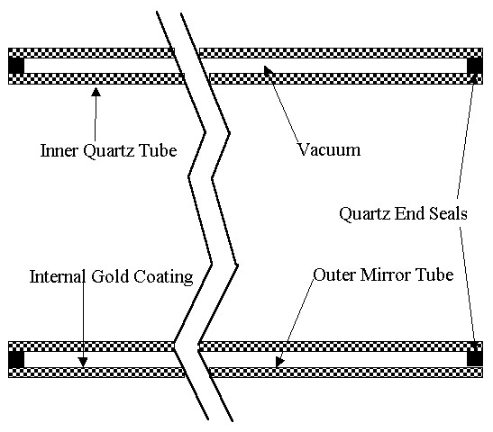
Figure 4. Schematic of double walled quartz vacuum jacket.
The solution offered here is to use fusion sealing similar to standard vacuum dewars made out of glass. The proposed insulating jacket consists of inner and outer quartz tubes where the ends are sealed with melted and fused quartz in a manner that permits the radial space between them to be evacuated. The basic geometry is shown in Fig. 4. The outer tube might also be the IR reflective mirror tube, and the inside may also be a coated tube.
The major question about this configuration is how much temperature difference can be tolerated between the inner and outer shells. In order to take advantage of the vacuum insulation, the primary temperature drop must be between the shells. However, if this is true, there will be a thermal expansion difference between the inner and outer shell that must tolerate the associated thermal stresses. This problem is discussed further below. Other critical issues are the vacuum level needed and the lifetime of this vacuum that can be maintained without vacuum pumping.
Convective Heat Transfer. Heat transfer [7] in all furnaces not operating at high vacuum is dominated at low temperatures by natural convection heat transfer from higher to lower temperatures regions. Convective effects are often enhanced by fluid circulation cells allowed by the internal furnace geometry and driven by temperature differences and buoyancy effects of adjacent hotter and cooler walls. For laminar flow, the heat transferred to a fluid from a flat plate is defined by a rate of heat transfer, q, and a heat flux, q/A, as q/A = (h)(Δ T) where A is the area of heat transfer, h is the heat transfer coefficient and Δ T is the temperature difference between the fluid and the surface. The heat transfer coefficient, h, is defined experimentally in terms of a Nusselt number, Nu, a thermal conductivity, k, and a flow length, L, as h = (Nu)(k/L). Orders of magnitude for h in W/m2-K are: 1) Gases in natural convection: 5-29, 2) Flowing gases: 11-290, and 3) Flowing liquids (non-metallic): 170-5700. Different flow and fluid regimes are defined by the dependence of Nu on flow parameters such as Reynolds number, ReL = ρ uL/µ , the Grashof Number (Gr = ratio of buoyancy to viscous forces), and the Prandtl number, Pr = cpµ /k, where ρ is the fluid density, u is the fluid velocity, L is a characteristic length, and µ is the fluid viscosity. Many correlations give Nu for different geometries and fluids. Natural convection can occur as laminar or turbulent flow, where hotter objects cause larger buoyancy forces, higher flow rates, and turbulent flows. Gas/surface heat transfer is controlled by thermal contact resistance, which depends on parameters such as surface roughness and deposits.
Convection Elimination - Vacuum Design: Elimination of thermal convection by removing the medium responsible for the convection is an obvious goal that is difficult to achieve in practice. Convective heat transfer is not directly proportional to the gas density, but is proportional to the square root of the density through a dependence on the 1/4 power on the Grashof number for free convection heat transfer, which translates into a 1/2 power dependence on gas density. The thermal conductivity of a gas decreases even more slowly with pressure down to 10 torr or less, then drops rapidly [4]. These effects explain the fact that only minor decreases in heat transfer occur as pressure is reduced, unless the pressure is lowered by many orders of magnitude. Previous experimental work at Thoughtventions has shown that pressures of 1-10 mtorr are required to eliminate convective effects.
The design of a furnace that relies on a vacuum pump to operate without convective heat losses then consists of defining the pumping rate and vacuum conductances needed to achieve at least this level of vacuum. The geometry and spacing between the outer shell and next inner furnace component must be large enough to permit adequate pumping of every part of the volume; the molecular flow cannot be limited by any long passages. There is a flow resistance associated with pumping through a large L/D passage; if the flow resistance is too high then it limits the vacuum achievable at the far end independently of the pumping rate at the base. Even without a leak to pump out in the closed shell, there is always surface contamination that provides a virtual gas source. A typical case is air moisture, which is in equilibrium with the walls. Initial pumping quickly removes the gases and the bulk of the vapor, but water adsorbed/absorbed on the wall must be evaporated and then pumped to the appropriate vacuum level. The required low vacuum must be maintained when the furnace core is hot and outgassing naturally increases.
Operating vacuum levels can increase at high temperatures when the vapor pressure of any material in the furnaces increases sufficiently. In this case convective heat transfer increases, lessening thermal protection and leading to an unstable temperature increase where the furnace fails rapidly. Support materials (such as a silicate insulators) may have a high vapor pressure at the required operating temperature, and most metals have significant vapor pressures at high temperatures. A more subtle vapor source is surface films that form during operation. An example is molybdenum; the metal itself has negligible vapor pressure at temperatures on the order of 1000°C, but if exposed to small quantities of air, a surface film of Mo oxide is formed, which evaporates ot much lower temperature than the metal causing significant pressures in a vacuum system.
Although convective losses at low pressure are somewhat geometry dependent, vacuum levels on the order of 1-10 parts per million of an atmosphere pressure are required to eliminate significant convection. A good diffusion pump is required rather than a mechanical pump. At low pressures heat losses resulting from gas convection are extremely low. The thermal conductivity of gas at low pressure is on the order of 3-4 x 10⁻⁷ W/cm-K [4]. For a thermal gradient of 600°C over 3 mm heat fluxes are 6 x 10⁻⁴ W/cm2; for an area of 2,000 cm2 convective heat losses will only be 1.2 W, a negligible amount.
High Temperature Transparent Materials. Transparent furnaces have traditionally been constructed using quartz tubes. Quartz has a softening point at 1670°C, an annealing point at 1140°C, and a strain point 1070°C. However, quartz is commonly used at temperatures up to 1400°C in the semiconductor industry, where very clean conditions prevent devitrification and rotation prevents sagging. GAS is grown at 1250°C.
The weakness of quartz as a material is its sensitivity to chemical attack at higher temperatures and its slow sagging. Although both of these weaknesses will prevent the use of quartz at temperatures much higher than 1200°C, it has been shown to be adequate for operation at these temperatures except for very long runs. The strength of quartz increases with temperature. Chemical attack can be prevented by standardizing cleaning procedures and using pure gases (necessary for proper sample control in any case). Sagging is slow and can be compensated for by rotation of the quartz to prevent significant sagging in any one direction. It is believed that the great additional cost of alternate materials outweighs their advantages at the target temperature, although materials such as sapphire must be used for higher temperature operation. A sapphire furnace tube has been found by Thoughtventions to be of moderate, but not prohibitive, cost.
Vacuum Seal. The vacuum seal is done in the same way that quartz crystal growth ampoules are made. The volume between the tubes is pumped out through a quartz tube. While the vacuum is maintained, the tube is heated, stretched, and fused to seal it. One issue with this procedure is to make sure that the wall thickness at all locations is sufficiently thick for strength and to prevent air diffusion through the wall.
An operating note for the vacuum jacket is that its operating lifetime will be significantly decreased by the use of hydrogen or helium in the furnace. These gases have much higher diffusion rates through solids than other gasses, and can be expected to decrease the jacket lifetime by as much as an order of magnitude.
Vacuum Jacket Operation. In order to function as a convective heat barrier, the inner wall of the vacuum jacket will have to operate hot, while the outer wall operates cold, or at least much cooler. If the outer wall heats up, convective heat transfer will be reestablished outward from this boundary and heat transfer from the core will again increase. Ideally, the outer jacket will also be the mirror tube, so that the vacuum jacket provides a barrier to all types of heat transfer. The difficulty with this mode of operation is that there will then be significant thermal stresses on the quartz as a result of the temperature differences across the shell.
Thermal Stresses. The thermal expansion coefficient of quartz is very low: 5 x 10⁻⁷, but thermal stresses can cause failure in quartz because it also has a low tensile strength. The compressive strength of quartz is high - 1.1 x 10⁹ N/m2, but its tensile strength of quartz is only 4.8 x 10⁷ N/m2. Young's modulus for quartz is 7 x 10¹⁰ N/m2.
An approximate thermal stress can be calculated as follows. A 60 cm long quartz tube will grow by 0.3 mm as a result of the thermal expansion resulting from a 1000°C temperature increase. Assuming 2 tubes with ends fixed to be the same length, the growth of the hot tube causes an extension and tensile stress on the inner tube. Imposing an extension of Δ = 0.3 mm on the inner cold tube (at 0°C) implies a tensile load, P, such that P = kΔ , where k = AE/L, and A is the tube solid area, E is Young's modulus, and L is the tube length. Assuming a 5 cm diameter tube that is 60 cm long and 2 mm thick, a pressure, P/A, or effective tensile stress can be calculated as 3.5 x 10⁷ N/m2. This is below the tensile strength of quartz, but does not leave a large margin for a safety factor.
This thermal stress is an overestimate in one sense, because the quartz will flow in response to the compressive stresses on the high temperature wall, and decrease the stress on the cold tube. An unknown is the stress in the end joint.
Temperature Testing. Double walled vacuum shells will be tested to determine if the jacket fails when the inner jacket is hot and the outer jacket is cold. This testing will be done by heating the inside and cooling the outside, so that a failure does not destroy a mirror tube. Cooling on the outside will remove the radiant heat absorbed by the quartz. Inner and outer temperature will be measured, and the inner temperature will be steadily increased as high as possible. Thoughtventions has a wide variety of heater coils that can be used to perform these experiments.
Some analysis will be performed to explore the stresses at the ends of the tube, and to determine whether there are benefits to extending the quartz tube so that the ends are cold.
Vacuum Lifetime. The diffusion of air through a quartz tube wall is very slow, and standard dewars are known to have a very long lifetime. The pressure rise caused by the permeation through a one-liter container of chemical Pyrex (7740) is on the order of 10-5 torr/year [8]. It is anticipated that a quartz double vacuum jacket will last the lifetime of the furnace in terms of internal pressure rise.
Transparent Furnace Fabrication.
The fabricater gold-coated tube(s) will be combined with the vacuum jacket and used to fabricate a prototype transparent furnace that will be used for testing. The nominal parameters of the furnace are shown in Table 1. These parameters are designed to be consistent with related shells that have been fabricated and tested at Thoughtventions, so that previous test results will be applicable.
Prototype furnace construction. The basic furnace design is to build the furnace up in concentric layers. The innermost element is a quartz tube that shields the workpiece from the heater coil. At a larger radius are kanthal coils, mounted on slotted rods to keep the individual turns in place as the furnace is heated. The coil spacing is designed to provide uniform heating yet provide adequate visibility through the spaces between the turns. Next will be another quartz shell to protect the vacuum jacket, although this may not be necessary. Last comes the double-walled vacuum jacket, with an outer gold-coated tube. For very high temperature operation, or if there are problems integrating the gold coated tube into the vacuum jacket, the performance of the furnace can be found using an outer separate mirror tube.
End radiation shields will be used to decrease the overall furnace power levels. Thoughtventions already has a set of end shields, aluminum end blocks with T/C and power feedthrus, and a variety of quartz tubes that can be used as protective shells.
Table 1. Transparent furnace nominal parameters.
Maximum Operating Temperature - 1200°C Optical Access -------- Transparent Sections
Furnace axis --------------------------- Horizontal Mirror tube length ----- 470 mm
Furnace power ------------------------ DC feedback controlled Heated length ---------- 260 mm
Workpiece max. diameter ----------- 50 mm Heater element -------- Kanthal
Coil support --------------------------- Three quartz slotted rods Furnace Power ------- 500 W or less
Furnace OD --------------------------- 115 mm Vacuum Insulation---Weld-sealed double quartz tube
Operating Temperature. The design operating temperature of the furnace will be nominally 1200°C. Thoughtventions has already built a transparent furnace operating successfully at this temperature shown in Fig. 5. The actual operating temperature of the furnace during tests will depend on the temperature tests of the vacuum jacket and the temperature of the outer mirror tube when the furnace is operating. If all goes as planned the 1200°C temperature goal should be no problem, but overall program success will be determined more by the success of the vacuum jacket and gold coated tubes; a lower temperature furnace would still be a very valuable device.
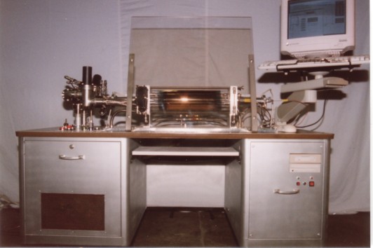
Figure 5. Photo of Thoughtventions's 1200°C commercial Transparent Furnace.
Furnace Testing
Alpha prototype testing. The alpha prototype will be operated at a progressively higher core temperatures and the temperatures of the shells will be measured for comparison with modeling and predicted behavior. Temperature data will be recorded using a computer data acquisition system so that the time response of the furnace can be examined carefully. Temperatures of the coil, the load, the end caps, the end radiation shields, and the mirror tube will be continuously monitored using standard thermocouple instrumentation. Prototype testing will be done both to document performance and to assure proper functioning of all components. Furnace core temperatures of up to 1200°C will be tested if possible. Furnace power consumption and electrical characteristics will be measured. Electrical power use is easily measured, but heat release from the furnace will have to be inferred from a variety of experimental data. Whether the furnace is performing as well as expected will also be determined by comparing furnace performance with a wealth of data from Thoughtventions's previous work with a variety of similarly configured furnaces.
The critical performance factors of the alpha prototype are achievement of a stable, high operating temperature and low furnace power. Stable high temperature operation will demonstrate that the furnace components are not degrading with use. Low furnace power will demonstrate the success of convective and radiative heat confinement. If the jacket performs as expected the power requirements of the furnace will be dramatically reduced compared with standard transparent furnaces models, and increased end losses will only mean an increase in the small amount of power required. A temperature increase from approximately 925°C to 1150°C implies an increase by a factor of 2 in radiated power as a result of T4 power dependence; high temperature testing will be the most stringent test of radiation confinement.
Low Power Testing. The approach to building a low power furnace has been studied extensively as a result of Thoughtventions's previous low power furnace program [9]. The basic design is to eliminate convective heat loss by using high vacuum insulation, to minimize radiation heat loss by surrounding the hot zone with low emissivity/high reflectivity materials, and to minimize conduction heat loss by using a small area, low thermal conductivity support structures. The medium-sized low power furnace developed at Thoughtventions, but not fully optimized, used only 85 W at a coil temperature of 600°C. This can be compared with the same furnace operating at the same core temperature using vacuum insulation that used a power of almost 2 kW because it used a quartz outer shell instead of a mirror tube. These low power experiments and their associated temperature and heat loss experiments demonstrated that the furnace and the furnace design was operating in a new regime where small effects in normal furnaces dominate the heat losses in this low power furnace. Heat loss channels on the order of 10 W become important, power measurements are more difficult, and outer shell temperatures become uncertain as a result of fluctuations caused by natural convection cooling.
Power Measurement. The accuracy of power measurement using standard techniques is poor at the low power levels that will be used by the furnace. The furnace will be driven by a standard SCR-controlled AC power supply, so that accurate power measurement requires a detailed integration of the voltage and current waveforms. More sensitive isolated phase sensitive current and voltage sensors purchased and used for the low power furnace project will be combined with a digital oscilloscope to provide an accurate power measurement.
Energy Balance/Calorimetry. Electrical power use is relatively easily measured with sophisticated equipment, but an accurate calculation of the energy balance of the furnace is extremely difficult because of the small absolute magnitudes of the heat losses and the importance of thermal contact resistances, which are difficult to measure or estimate. Previous modeling, experiments, and analysis of heat loss channels will be used to give information about the individual heat loss channels in the furnace. Convective radial heat loss should be less than 1 W total: insignificant for this program if the vacuum in the jacket is maintained.
It is essential that the furnace of this program contain the radiant heat emitted from the furnace core. Estimating and ranking the radiative heat sinks consists of calculating their absorptivity, their area, and the radiant power incident on their surfaces; any clear apertures in the furnace are considered total absorbers. The areas of the absorbing surfaces are easily calculated. The largest by far is the mirror tube, with an area of about 2,000 cm2. The end shields, without penetrations, have an area of 70 cm2 each. Thus, if the mirror tube absorbs 2% of the radiation incident on it, this is an equivalent heat loss to a single end shield absorbing 20%, which is roughly the comparative emissivities of gold and molybdenum. Four radiation shields in sequence reduce the radiation by a significant factor compared with just one. Temperature drops of 20-50°C per shield are common at moderate temperatures (600°C), determined as much by conductive as radiative heat transfer. All of the furnace surfaces can be analyzed in this way to determine the major radiative loss channels.
Furnace Power. Thoughtventions has a wide variety of transparent furnace power data. For standard transparent furnaces, operation at temperatures above 1100°C requires high power (over 3 kW for a furnace of the size described in Table 1) and results in limited life. For a vacuum transparent furnace of similar size, operation at 900°C has been shown to require between 600 and 650 watts. Of this power approximately 1/3 is radial losses and 1/3 is lost out each end. At 1200°C the radiant power has increased by a factor of 2.5, and since the power is almost entirely radiative (a small amount is conductive) the potential power losses increase by this factor. The power used by Thoughtventions vacuum transparent furnace at 1200°C was about 1500 watts, although the power radiated by the coil is about 4 kW.
Changing the transparent furnace from one with a semi-transparent shell, to one with an opaque gold coating and a limited semi-transparent region (as is proposed here) is expected to decrease the furnace power significantly. Thoughtventions's low power furnace (a similar size) used 85 W of power for a coil temperature of 600°C. Operation of this furnace at 1200°C should result in a power less than 500 W. The measured furnace power will be a good indicator of how good the heat containment is. It should be noted that a low power furnaces will have a long cooldown time, unless active measures are taken to cool them.
Transparent Furnace Heat Transfer Modeling. Thoughtventions has been developing heat transfer modeling for its cylindrical furnaces for 5 years, and has a series of detailed models in place that have been used to analyze the furnace heat transfer behavior and to predict experimental results. The models allow radiation, convection, and conduction heat energy loss channels to be defined and ranked, and allow their variation with furnace size, shape, etc., to be explored in order to define the behavior of a specific furnace or to optimize a prototype design.
Since the transparent furnace operates as a steady state device, the power dissipated as an electrical load in its heating element must equal the heat power lost from the furnace through convection, radiation, and conduction at the external envelope of the furnace. This balance provides the framework of the model. The coil provides the driving power, this power is transferred to the outer envelope of a standard furnace through radiation, convection, and, to a lesser extent, conduction. The heat power emerges from the furnace either as 1) radiation that is transmitted directly from the heating element to the external environment through all of the inner quartz shells and the mirror tube, or 2) heat that has been relayed by convection, conduction, and radiation to the external shell where it is primarily carried away by natural convection, assuming an uncooled system. Conduction losses are all end losses through the gas tubing connections, the electrical connections, and the supports for the quartz shells. Conduction losses also finally become primarily convective losses in this case, rather than being absorbed to heat solid objects, because of minimal large-area thermal contact.
Heat transfer theory is well known in general but has a number of critical factors that are difficult to calculate in detail. These factors include emissivity, contact resistance, complex geometric effects, and flow patterns for convective heat loss. High temperature heat transfer is dominated by radiant heat transfer in most cases, increasing in proportion to T4 (in degrees K), because careful thermal isolation must have been done to achieve such temperatures for practical heating powers. For transparent furnaces, most of the heat absorbed by a workpiece is transferred by radiation, and this radiation must be contained in the furnace. In standard furnaces the walls are opaque, thermally isolated, and in radiant equilibrium at high temperatures with the entire interior of the furnace.
An algebraic computer model of the heat transfer in the transparent furnace has been created using MATHCADTM. This type of model allows rapid evolution of the model physics including radical changes in form, and rapid trial of concepts where experiments are impractical. Temperatures are chosen for the coil and the quartz shells, and the heat transfer factors between components are then calculated using standard radiation heat transfer and relevant convective heat transfer correlations. A correct solution is found when the heat transfer is the same through each interface of a cylindrical shell except for the radiant heat transfer at wavelengths less than 4 µ m which is absorbed and deposited directly into the mirror tube. Iteration is rapid since the calculations are instantaneous once the temperatures are entered.
Radiation Modeling. Radiative heat flows depend in general on the temperature and radiating characteristics of the radiating surfaces. For a transparent furnace the driving source of radiation is the heating element, which is kanthal in the case of the 1200°C transparent furnace planned for this program. Derivative sources, which in this case are also major radiators, are the sample itself and the quartz tubes and support rods that surround the heater element. All radiative sources emit as blackbodies modified by the emissivity of their surfaces, which depend on the wavelength of the radiation and a variety of surface properties. Determining the detailed emissivities and absorbances of the mirror shell is important, since radiant heat transfer dominates the energy balance at high temperatures. Although radiation containment dominates the furnace design more and more at higher temperatures, small losses as a result of all causes become significant because the internal heat fluxes are so large and the tolerable external heat fluxes are fixed.
The standard transparent furnace has a number of important peculiarities with respect to radiant heat transfer. The most obvious source of radiation is the heater coil, but inside the furnace the quartz shells dominate both the radiant heat transfer and the overall heat transfer in the furnace. The heater coil radiates more power than any other source in the furnace, but most of that power is confined within the furnace by the IR reflecting mirror tube, and only absorbed by the insulation at the furnace ends and by the coils themselves. The wide spacing and relatively small diameter of the heater coils makes the total radiating area of the coil less than that of the smallest quartz shell. The small coil surface area also implies that the total radiated power inside the furnace will be significantly increased by adding a large sample in the furnace even though the sample is at a lower temperature than the coils.
The quartz tubes used in the transparent furnace are only transparent at visible and near infrared wavelengths. Quartz absorbs all radiation beyond 3 - 5 µ m wavelength, depending on the type of quartz used. The mirror tube in a transparent furnace uses special IR transmissive quartz (GE type 124). For thicknesses over 1 mm, this quartz absorbs all radiation with wavelengths longer than 5 µ m. Absorption begins at about 4 µ m and is 40% at 4.5 µ m. The absorptivity of a material surface equals its emissivity, so the quartz in the furnace absorbs and radiates at wavelengths longer than 4.5 µ m. Assuming a sharp absorption cutoff at 4.5 µ m m (a good approximation) the radiative power absorbed in the quartz can be calculated by integrating the blackbody spectrum given above from 4.5 µ m to infinite wavelength.
These calculations showed that at 900°C, 32% of the blackbody radiation is absorbed by the quartz. At 1000°C 27.5% is absorbed, and at 1200°C 20.5% is absorbed. The absorption in the quartz is a thus a significant part of the total radiated power at the temperatures relevant to this program. It is important to note that although the fraction of power deposited in the quartz decreases with temperature, the absolute magnitude of the power deposited increases steadily; not as fast as the total power (T4), but with a temperature dependence between T2 and T3. This power deposition will be a more significant problem as the temperature rating of the furnace increases.
The radiant heat transfer in the furnace occurs in three wavelength regions. In the near infrared spectrum for wavelengths less than 4.5 µ m that are reflected by the mirror tube the radiant power is absorbed by the coil itself, by the sample if there is one, by the binder of the gold coating, and by the insulation at the end of the furnace. At visible wavelengths the radiant power is primarily absorbed by the mirror coating and the external environment. At wavelengths longer than 4.5 µ m there is a radiant equilibrium between each concentric pair of quartz shells. The hotter inner shells provide most of the heating for the cooler outer shells, which are in turn cooled by radiation outward and convection, while simultaneously reradiating a lesser amount of heat back to the inner shell.
The mirror tube forms the boundary for the radial radiant heat transfer in the furnace. The mirror tube nominally reflects the IR radiation incident on it to contain the radiant heat in the furnace. The transparent section of the mirror tube passes a significant fraction of the visible radiation so that furnace processes can be observed. In this section radiant absorption occurs in the mirror coating and in the quartz itself, degrading the efficiency of the IR radiation reflection.
Modeling of End Heat Losses. For the overall energy balance, end heat losses in the transparent furnace are a result of radiation, convection, and conduction. For most tube furnaces end losses are relatively insignificant, given end insulation thicknesses similar to that used for radial insulation. This situation is changed dramatically when radial convection heat transfer is eliminated and radial radiation heat transfer is greatly reduced. End losses then dominate furnace heat loss and strongly interact with the radiation trapped within the furnace.
It is estimated that over half of the radiation reflected at the vacuum mirror tube wall may be finally lost through the furnace ends without end radiation shields, rather than being reabsorbed by components in the furnace to reduce the electrical power required for heating. A typical furnace geometry has a mirror tube of 85 mm OD and 215 mm in length. With this aspect ratio there are major end losses. Longer mirror tubes have been built, which would reduce the problem, but eventually end losses will have to be reduced by reflectors at the ends of the tubes. Multiple end radiation shields reduce losses, and reduce convective end losses as well.
Primary conduction heat loss channels are solid paths from the hot zone to the cool outside of the furnace. In the experimental furnace this consists of the heat shield supports anchored in the end caps, and the heater element current feedthrus. For normal furnaces, the current feedthrus must be substantial to carry the necessary furnace power. For a low power furnace the feedthrus can be made smaller with convoluted paths to reduce conductive heat transfer. Quartz heater coil supports have the advantage of low thermal conductivity, but are physically fragile and act as a conduit for radiant energy.
Surface Degradation. Surface degradation during tests will be assessed by visual and microscopic inspection between tests if appropriate. Increased radiation absorption is the ultimate test of surface contamination, so benchmark initial testing will be performed and repeated periodically. Benchmark testing will consist of defining a specific coil operating temperature and an associated operating power.
Load Dependence. The operation and use of a high heat containment furnace is significantly different from furnaces currently in use. The thermal control and the thermal time constants of the furnace will be dominated more by the load in the furnace than by the furnace itself. The furnace performs as a high vacuum furnace, where at all temperatures heat transfer occurs as a result of heat radiation (not by convection) rather than just at high temperature. This changes the design of multizone furnaces, and necessitates a careful assessment of the radiant absorption characteristics of the load to determine its thermal response to furnace control.
References
1. T.B. Reed, "Transparent Furnace for Vapor Crystal Growth," Solid State Research Report, Lincoln Lab, MIT, 1, 21, (1969).
2. P.G. Schunemann and T.M. Pollack, "ZnGeP2 Crystal Growth Studies uning the Horizontal Gradient Freeze Technique," Tenth Intnl. Conf. on Crystal Growth, Aug. 16-21, San Diego, CA, (1992).
3. OMEGA Temperature Data Book, Vol MM, Omega Engineering Inc., Stamford, CT, (1999).
4. W.L. Wolfe and and G.J. Zissis Eds., The Infrared Handbook, Environmental Rsch Inst. of Michigan, Ann Arbor, MI, (1993).
5. G. Hass, "Reflectance and preparation of front-surface mirrors for use at various angles of incidence from the UV to far IR ," J. Opt. Soc. Am., 72, 1, 27 (1982).
6. Ed. D.E. Gray, American Institute of Phystics Handbook, McGraw-Hill, NewYork, NY, (1972).
7. W.M. Rohsenow and H. Choi, Heat Mass and Momentum Transfer, Prentice Hall, New York, (1961).
8. W.H. Kohl Ed., Handbook of Materials and Techniques for Vacuum Devices, Reinhold Publishing Co., New York, NY, (1968).
9. S.C. Bates, "Low Mass, Low Power, Low Cost Space Furnace," SBIR Phase I Final Report, NASA Marshall Space Flight Center, Contract # NAS8-99040, Sept., (1999).