LOW MASS, LOW POWER, LOW COST SPACE FURNACE
40 Nutmeg Lane
Glastonbury, CT 06033
ABSTRACT
The goal of this project has been to design and test a prototype low power, low mass, low cost space furnace. Vacuum and radiation insulation, coupled with low conductivity support paths provided a means to almost eliminate heat losses from the furnace, allowing elevated core temperatures to be achieved using very low power. The operating regime was found to be fundamentally different from standard furnaces; radiant heating dominates heat transfer in the furnace at all temperatures, previously small effects become important, and the furnace thermal inertia is very small. Iterations to decrease furnace power were made on the furnace supports, radiation shielding, and vacuum pumping. Low and high temperature radiation shield designs were created, together with the design of a space vacuum pump that would minimize radiation loss through the pumping port in the furnace. A beta prototype tube furnace was designed, fabricated, and tested, demonstrating a steady state power of less than 80 W at 600°C coil temperature. Feasibility was demonstrated by the low power levels achieved experimentally. The project has major commercial potential in supplying improved furnaces for a wide variety of thermal processing. The proposed furnace has major advantages for use on the space station in its low power and lack of need for support systems.
The Problem. Although it is believed that there are many reasons for being able to achieve superior thermal processing of materials in microgravity, major commercial applications are still being developed. Demonstration of the advantages of materials processing in space is hampered by the many constraints of launch and operation of the space shuttle. Earthbound furnaces require large amounts of power, massive containers, and extensive support systems; this type of furnace design is neither appropriate nor necessary in space. Shuttle accelerations, cost, complexity, facility operation difficulties, lack of real time experimental interaction with the operator, the inherently statistical nature of preliminary materials experiments, and shuttle scientist workload, all contribute to a lack of experimental results that might lead to a larger commercial materials processing effort in space. A simple, low cost, low power, utilitarian space furnace is needed.
The Innovation. The innovation of this proposal is the use of advanced techniques for heat containment to reduce the mass, power and cost of a high temperature furnace to be used in space. High vacuum insulation eliminates convection heat losses. Low emissivity radiation shields surrounding the hot zone eliminate most of the radiation heat loss without degradation over time. Minimal, insulated support structures minimize conduction heat losses. A cylindrical configuration provides strength, simplicity, and low mass. The low power regime of furnace operation is being explored, with improved control systems, heat loss channel analysis, and an emphasis on radiation heat containment, even at low temperatures. Vacuum pumping requirements for convection elimination are minimized by using the partial vacuum of space. Power and heat levels are so low that furnace work in space will be able to be performed virtually without the need for support systems. This furnace has the potential to be a valuable tool for research and development of materials processing in space.
Summary
Furnace operating goals were achieved by advanced heat containment design, proper low mass/support system design, and radiation shield development. These design components were combined to fabricate a furnace that was used to experimentally demonstrate the low power furnace and to iterate on the design and construction to lower power to very low levels.
Research results consist of:
1) Created a furnace heat loss design that minimizes convection, conduction, and radiation.
2) Created a hot zone support design to minimize thermal conduction.
3) Created a furnace vacuum design that maintains a low pressure through radiation shielding.
4) Created a novel vacuum pumping design appropriate for use in space that minimizes radiation loss through the pumping port while maintaining high vacuum pumping.
5) Created a radiation shielding design to contain multihundred watt radiation within the furnace while minimizing radiation absorption in the outer shell of the furnace.
6) Fabricated and tested an inexpensive gold coated outer radiation shield.
7) Fabricated and tested sets of axial radiation shields.
8) Fabricated and tested high temperature gold radiation shields.
9) Fabricated a test furnace for experiments.
10) Experimentally demonstrated principles and designs for minimizing convection, conduction, and radiation heat losses in the furnace.
11) Predicted and confirmed experimental heat loss channels.
12) Demonstrated furnace operation at minimal power levels that will require no cooling of furnace components.
13) Gold coated outer mirror tube operating at less than 60°C without any cooling.
14) Operation at 600°C coil temperature using less than 80 watts of electrical power.
An accurate drawing (half scale) of the experimental furnace is shown in Figure 1 to provide a context of the discussion of Phase 1 results. This is a resistance heated tube furnace with a high vacuum maintained inside the furnace shell. The hot zone is bounded axially by 4 radiation shields. The 3 shield supports (spaced 120° - one shown) also support the 3 slotted coil support rods (spaced 120° - one shown). Pumping holes in the shields are not shown, nor are the current feedthru insulators.
Heat Containment Design.
The heat transfer design of Phase 1 consists of vacuum insulation to eliminate convective heat losses, low emissivity, high reflectivity walls surrounding the furnace core to minimize radiative heat losses, and minimal, low thermal conductivity material supports for the furnace core to reduce thermal conduction. Reduction of convective and conductive heat transfer has been achieved to the extent that these are minor effects. The difficult aspect of the project has been to identify and minimize radiation heat transfer pathways and mechanisms.
Heat flux phenomena in furnaces are well known, at least in clean furnaces. For standard one atm furnaces at lower temperatures convection and conduction dominate heat transfer, whereas at higher temperatures radiation dominates. In these furnaces, the important change in heat transfer that occurs with temperature is the onset of radiant heat transfer in the temperature range 500-700°C. Techniques that reduce radiant heat transfer are fundamentally different from convective and conductive heat transfer reduction, requiring the use of special materials and the preparation/maintenance of special surfaces that emit/absorb little radiation and reflect most radiation. For the present project it has been found that vacuum insulation and insulating mounting makes the dominant form of heat transfer radiation even at low operating temperatures.
Convective Heat Transfer Environment. Heat transfer in all furnaces not operating at high vacuum is dominated at low temperatures by natural convection heat transfer from higher to lower temperatures regions. Convective effects are often enhanced by fluid circulation cells allowed by the internal furnace geometry and driven by temperature differences and buoyancy effects of adjacent hotter and cooler walls. For laminar flow the heat transferred to a fluid from a flat plate is defined by a rate of heat transfer, q, and a heat flux, q/A, as q/A = (h)((T) where A is the area of heat transfer, the factor h is the heat transfer coefficient and (T is the temperature difference between the fluid and the surface. The heat transfer coefficient, h, is defined experimentally in terms of a Nusselt number, Nu, a thermal conductivity, k, and a flow length, L, as h = (Nu)(k/L). Orders of magnitude for h in W/m2-K are: 1) Gases in natural convection: 5-29, 2) Flowing gases: 11-290, and 3) Flowing liquids (non-metallic): 170-5700. Different flow and fluid regimes are defined by the dependence of Nu on flow parameters such as Reynolds number, ReL = (uL/(, the Grashof Number (Gr = ratio of buoyancy to viscous forces), and the Prandtl number, Pr = cp(/k, where ( is the fluid density, u is the fluid velocity, L is a characteristic length, and ( is the fluid viscosity. Many correlations give Nu for different geometries and fluids. Natural convection can occur as laminar or turbulent flow, where hotter objects cause larger buoyancy forces, higher flow rates, and turbulent flows. Heat transfer from the gas to the surface is controlled by thermal contact resistance, which depends on parameters such as surface roughness and deposits.
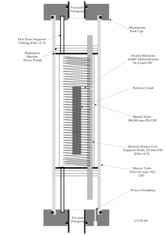
Figure 1. Prototype furnace cross-section schematic.
Convection Elimination - Vacuum Design: Elimination of thermal convection by removing the medium responsible for the convection is an obvious goal that is difficult to achieve in practice. Convective heat transfer is not directly proportional to the gas density, but is proportional to the square root of the density through a dependence on the 1/4 power on the Grashof number for free convection heat transfer, which translates into a 1/2 power dependence on gas density. Furthermore, the thermal conductivity of a gas decreases even more slowly with pressure down to 10 torr or less, then drops rapidly. These effects cause only minor decreases in heat transfer to occur as pressure is reduced, unless it is decreased by many orders of magnitude. Tests at Thoughtventions confirm other experiment work that show that pressures on the order of 1-10 mtorr are required to eliminate convective effects.
Vacuum design for a furnace without convection then consists of defining the pumping rate and vacuum conductances needed to achieve at least this level of vacuum. The geometry and spacing between the outer shell and next inner furnace component must be large enough to permit adequate pumping of every part of the volume; the molecular flow cannot be limited by any long passages. There is a flow resistance associated with pumping through a large L/D passage; if the flow resistance is too high then it limits the vacuum achievable at the far end independently of the pumping rate at the base. Although it might seem that this is irrelevant when there is no gas source to pump out in the closed shell, there is always surface contamination that must be pumped out. A typical case is air moisture, which is in equilibrium with the walls. At startup, the gases and the bulk of the vapor is quickly pumped out, but water adsorbed/absorbed on the wall must be evaporated and then pumped. Operating pressure must be achieved before the furnace core is hot.
Operating vacuum levels can increase at high temperatures when the vapor pressure of any material in the furnaces increases sufficiently. In this case convective heat transfer increases, lessening thermal protection and leading to an unstable temperature increase where the furnace fails rapidly. Support materials (such as a silicate insulators) may have a high vapor pressure at the required operating temperature, and most metals have significant vapor pressures at high temperatures. A more subtle vapor source is surface films. An example is molybdenum as used in the Phase 1 furnace. The metal itself has negligible vapor pressure at temperatures on the order of 1000°C, but if exposed to small quantities of air, a surface film of Mo oxide is formed. This film will evaporate causing significant pressures in a vacuum system.
Although convective losses at low pressure are somewhat geometry dependent, vacuum levels on the order of 1-10 parts per million of an atmosphere pressure are required to eliminate significant convection. A good diffusion pump is required rather than a mechanical pump. Thermal conductivities on the order of 10-7 W/cm-K can be achieved. In the case of the geometry of the furnace used in Phase 1, this heat transfer rate translates into less than 1 watt of total heat loss, and a negligible factor in furnace operation.
Conductive Heat Transfer. Conduction is a relatively minor effect for small furnaces that need not support internal loads with large masses. In the case of a space furnace, since gravity is not an issue during operation, launch forces (and vibration) will determine the strength (and thus mass) of the physical connections inside the furnace. Launch supports are made in a lock-down configuration so that they can be released in space to eliminate major conductive heat loss paths. Care must be taken to avoid large thermal gradients within components, however, to avoid associated large thermal stresses.
Primary conduction heat loss channels are solid paths from the hot zone to the cool outside of the furnace. In the experimental furnace this consists of the heat shield supports anchored in the end caps, and the heater element current feedthrus. The use of quartz heater coil supports has the advantages that the thermal conductivity of quartz is very low, but the disadvantages that it can act as a conduit for radiant energy, and that it is a fragile material.
Initial efforts to reduce conduction focussed on solid 6 mm diameter steel rods that were used to support the hot zone. Calculations indicated that the heat loss through these would be tens of watts, so the supports were changed to be tubing. For a temperature at the last radiation shield of 500°C (the core temperature will be significantly higher) it was calculated that 5 watts were lost from each end of the furnace through the tubing. This can be further reduced by using a material with a lower thermal conductivity.
The current feedthrus were found to be another heat conduction loss channel. Typically vacuum feedthrus must be substantial to tolerate both high currents and the structural requirements of rigidity for a vacuum fitting. They must also be made of low electrical conductivity material to prevent excessive heating of the feedthru itself from the large electrical currents. The initial feedthrus were 0.64 cm diameter beryllium copper commercial units made for standard furnaces. It is believed that these feedthrus accounted for the majority of the heat loss for the 80 W second iteration furnace. Details are given in the Task 4 furnace analysis. A materials analysis indicates that Nickel offers a significantly better compromise between thermal and electrical conductivity - almost 30% better than copper; although it has a significantly lower electrical conductivity it has a much lower thermal conductivity.
Secondary conduction heal loss channels consist of solid paths where heat is conducted from parts of the furnace that are heated directly by radiation. Since the primary work of Phase 1 is to eliminate this radiative heat transfer, the secondary conduction heat loss was used more as a diagnostic for radiative losses than as a means for reducing overall heat loss.
Radiation Heat Transfer. At high temperatures (> 1000oC) and at low temperatures in vacuum, radiant heat transfer is the dominant mechanism for heat transfer. Radiation heat loss is defined fundamentally by the Planck function as it describes blackbody radiation - a body that absorbs all incoming radiation. The intensity of this radiation is described as
W(λ,T) = c1/ [λ 5)(ec/λ T - 1)]
W(λ,T) is defined as the power radiated per unit wavelength interval at wavelength λ by a unit area of a blackbody at temperature T, where T is measured in degrees K, and c1 and c are constants. The total radiated power by a blackbody at temperature, T, is given by the Stefan-Boltzmann function:
Wtotal(T) = 5.679 x 10⁻¹² T4 W/cm2
The T4 dependence of the radiated power accounts for the dominance of radiation at high temperatures. Radiation increases rapidly with temperature, while the bulk of the radiant energy moves to lower wavelengths for higher temperatures. For real materials the total radiated power differs from that of a blackbody by the total emittance, et, such that
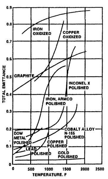
Figure 2. Metal emissivities as a function of surface condition and temperature.
Wreal(T) = ε t(T)Wblackbody(T)
Total emittances are integrals over wavelength of detailed emissivities that are also wavelength dependent. Total emittances can be quite low, but are usually depend strongly on temperature, increasing with temperature as shown in Figure 2[2]. The theoretical descriptions of the optical constants of solid, pure materials are reasonably well known, but the optical properties of materials at high temperatures have not been extensively measured.
Heat Transfer Modeling and Analysis. Thoughtventions has been developing heat transfer modeling for its cylindrical furnaces for 5 years, and has a series of detailed models in place that have been used to analyze the furnace heat transfer behavior and to predict experimental results. The models allow heat energy loss channels to be defined and ranked, and allow their variation with furnace size, shape, etc., to be explored in order to define the behavior of a specific furnace or to optimize a prototype design.
Heat Transfer in a Cylindrical Furnace. For a cylindrical furnace operating as a steady state device the power dissipated as an electrical load in its heating element must equal the heat power lost from the furnace through convection, radiation, and conduction at the external envelope of the furnace. This balance provides the framework of the modeling. For a furnace without optical access, the heat power emerges from the furnace relayed by convection, conduction, and radiation to the external shell where it is primarily carried away by natural convection, assuming an uncooled system. Conduction losses are all end losses through the gas tubing connections, the electrical connections, and the supports for the radial insulating shells. Conduction losses usually finally become primarily convective losses in this case, rather than being absorbed to heat solid objects because of minimal large-area thermal contact.
Heat transfer theory is well known in general but has a number of critical numerical factors that are difficult to calculate in detail. These factors include emissivity, contact resistance, complex geometric effects, and flow patterns for convective heat loss. In standard furnaces the inner wall surrounding the furnace element is opaque, thermally isolated, and in radiant equilibrium with the entire interior of the furnace. For high temperature furnaces the region immediately beyond the heating element is also usually enclosed by a series of radiation shields.
A detailed MATHCAD model was used to predict the behavior of the furnace, and has provided the calculated results. This model has been extensively verified in a number of furnaces experiments.
Radiation Modeling. Radiant emission is determined by a body's temperature, its detailed emissivity, its area. Radiating bodies are rarely isolated, but function in equilibrium with other radiating bodies around them. The initial and driving radiation source for the furnace is the electrically heated coil. In the case of the present furnace, the coil has been made from molybdenum to take advantage of this material's tolerance of both high temperatures and vacuum. Molybdenum has the unusual property that its high temperature emissivity is low - about 0.11, which accounts for its use as a high temperature radiation heat shield. The relatively small coil surface area also implies that the total radiated power inside the furnace will be significantly increased by adding a large work piece in the furnace, even though the sample is at a somewhat lower temperature than the coils. A muffle tube placed around the coil to make the temperature more uniform or to act as an intermediate radiation barrier also may emit more radiation than the coil.
The key element of radiation modeling and design is the interaction of the various radiating parts of the furnace. Controlling this interaction is the view factor of the various surface (the fraction of hemispherical radiation intercepted) and the relative temperatures and emissivities of the bodies. Translucent or partially transparent materials complicate the interaction. For two gray (ε t < 1) opaque surfaces, each of which has an unobstructed view of the other, the net heat flux between the surfaces is:
q12,net = A1F12σ (T14 - T24)
Where F12 is an emissivity fraction, for infinite parallel planes defined as:
F12 = 1/(1/ε 1 + 1/ε 2 - 1)
Note that for surfaces where ε is a small fraction, the net heat flow is essentially totally defined by the temperature of the hotter body and the emissivity of the more reflective/low emissivity body. For a cylindrical furnace such as that shown in Fig. 1, the equation is modified by the relative areas of the radiating bodies; the high temperature inner core having a smaller area relative to the outer low emissivity mirror tube. The total heat flow that is absorbed in the outer shell is not area dependent, however; the lower heat flux is balanced by the larger area.
An important special case is that where an enclosing gray body is put in place between the hot zone and the outer shell. This intermediate body, or radiation shield, floats in temperature at a temperature between the hot zone and the outer shell that is determined by its emissivity relative to the bodies it separates. In this case F12 is replaced by a similar equation with another inverse emissivity in the denominator. For a series of n radiation shields of the same emissivity, the factor F12 is reduced by [1/(1+n)] [3], without taking into account the wavelength sensitivity of the emissivity. In general, radiation heat transfer can be extremely complex, and will be different for diffuse and specular reflectors.
Quartz is a common laboratory furnace material and has been used in this furnace as a furnace coil support. Quartz is an unusual material in that its thermal conductivity is an order of magnitude lower than most metals. In the present case it complicates the estimation of radiant heat transfer in that while it is transparent at visible wavelengths, it is opaque in the mid and far infrared. Quartz absorbs all radiation beyond 3 - 5 µ m wavelength, depending on the type of quartz used. IR transmissive quartz (GE type 124), for thicknesses over 1 mm, absorbs all radiation with wavelengths longer than 5 µ m. Absorption begins at about 4 µ m and is 40% at 4.5 µ m, so the quartz in the furnace absorbs and radiates at wavelengths longer than 4.5 µ m. Assuming a sharp absorption cutoff at 4.5 µ m (a good approximation) the radiative power absorbed in the quartz can be calculated by integrating the blackbody spectrum given above from 4.5 µ m to infinite wavelength. Quartz absorbs more thermal radiation at lower temperatures; at 500°C quartz absorbs 0.60 % of the total thermal radiation and acts like a blackbody with an emissivity of 1 for the absorbed longer wavelengths. At 900°C, 32% of the blackbody radiation is absorbed by the quartz. There is also a 4% surface reflection factor.
Low Emissivity Design. Most practical furnaces cannot be designed with low emissivity radiation shields. Low emissivity generally translates into high conductivity, which results in radiation shields being made of refractory metals. Metals are easily contaminated, either by vapor deposition from the work piece and other hot zone materials, or by reaction with gases in the furnace, most commonly oxygen or nitrogen. The contaminated surfaces almost never have low emissivity. Vacuum furnaces at least have the potential to maintain the emissivity of surfaces, but are subject to the same problems if care is not taken in the design. If the hot zone is completely enclosed by a material that has a very low vapor pressure at high temperature, then the surfaces can be kept at low emissivity. The emissivities of even the best materials increase with temperature, approximately as their electrical conductivities. Low emissivity design must also take into account the radiation temperature - silver is has very low emissivity in the infrared, but significantly higher emissivity at visible wavelengths; it is not well adapted to lower temperature radiation systems.
In order to fabricate a very low power furnace it is critical that very low emissivity surfaces be used. Typical of one of the best of these materials is gold, which has a nominal emissivity of 2% at 1 µ m wavelength and drops to 1% at 8 µ m wavelength. In radiation calculations the 1/ε gold factor of 50 dominates most other effects. If the emissivity rises to 3% as a result of surface contamination, absorbed power/power used in the furnace increases by 50%, therefore it is critical to use the lowest possible emissivity material and to prevent it from being contaminated. Any hole in the furnace has a emissivity of 1, so that the area of the hole represents losses equivalent to 50 times that area with a gold coated surface, assuming an emissivity of 2%. Such holes/apertures must obviously be minimized. Again assuming ε gold = 0.02, the use of an intermediate molybdenum radiation shield only decreases the furnace power loss by 20%. A critical factor in this case, however, is that the shield operates at a lower temperature where its radiation is more efficiently reflected by the outer shield.
Heat Loss Estimations: For the furnace shown in Fig. 1, heat lost through various channels can be estimated. Conduction only occurs down the shield support rods and the current feedthrus, and is estimated based on measured temperatures at each end of the tubes, the tube cross-sectional area, and the thermal conductivity of stainless steel. Convective heat loss is less than 1 W total and is insignificant if vacuum is maintained.
It is essential that furnace of this program contain the radiant heat emitted from the furnace core. Estimating and ranking the radiative heat sinks consists of calculating their absorptivity, their area, and the radiant power incident on their surfaces; any clear apertures in the furnace are considered total absorbers. The areas of the absorbing surfaces are easily calculated. The largest by far is the mirror tube, with an area of about 2,000 cm2. The end shields, without penetrations, have an area of 70 cm2 each. Thus, if the mirror tube absorbs 2% of the radiation incident on it, this is an equivalent heat loss to a single end shield absorbing 20%, which is roughly the comparative emissivities of gold and molybdenum. Four radiation shields in sequence reduce the radiation by a significant factor compared with just one. Temperature drops of 20-50°C per shield are common at moderate temperatures (600°C), determined as much by conductive as radiative heat transfer. All of the furnace surfaces can be analyzed in this way to determine the major radiative loss channels.
Another factor is the area of the furnace radiation source. It is incorrect to assume that the furnace is a blackbody radiating at the radius of the mirror tube. Predicting the view factor of an open coil is difficult. Rather than calculate this, the heat flows into the outer shell of the furnace and radiation shields were calculated based on measured temperature. The measured electrical power was then compared with the sum of the heat lost through the various channels to verify consistency.
Low Mass/Support System Design.
This task has been one of technology design and investigation, and has had a minor role compared with that of achieving a very low power furnace. The target application for this furnace is use on the space station, but for the International Space Station (ISS), furnace interfaces and resources are still in definition and not finalized. For gloveboxes (Shuttle and Microgravity Science Glovebox - MSG) and hitchhikers these have been established. The NASA SARGE (Standard Assurance Requirements and Guidelines for Experiments) document provides some details. Topics discussed are those characteristic of the specific furnace of this program.
Mass Reduction: Furnace. The most massive parts of a standard commercial furnace are the container/pressure vessel and the water cooling apparatus. The furnace proposed here for use in space will have a set of light cylindrical gold-coated shells, and aluminum end caps as a low-mass pressure/containment vessel. For a lower temperature vessel, the outer cylinders could be made of aluminum to keep cost down. Higher temperatures would require titanium or TiAl. There would be 3 concentric shells for the primary purpose of triple redundancy safety, but the triple shells would improve the thermal efficiency of the furnace by also functioning as radiation shields. The cylindrical geometry is inherently strong, especially vertically when used as a column to support launch acceleration. The O-ring pressure seals also form natural shock absorbers.
All of the internal components in the furnace are light, so the furnace core will have low thermal inertia. The end caps of the furnace will be a series of thin plates sealed to each cylinder with spacer column spread over the end area to provide maximum stiffness and vacuum access. Another mass saving will be to make the coil supports out of thin alumina tubes instead of solid quartz rods.
Support Systems. Support systems are a major part of mass requirement of a furnace. The cooling supply, power supply, and vacuum supply are all furnace subsystems that have substantial mass.
The proposed furnace has the major advantage of not requiring a liquid cooling system, or perhaps not even an air cooling system. A furnace power of less than 80 W has been demonstrated in Phase 1; this amount of power can be removed conductively to the facility wall, where it will be a comparatively small overall heat load that can be handled by the overall station thermal control systems.
A separate power supply for the furnace will not be required as a result of the low furnace power demand. It will probably be advantageous to include a low-mass, high energy capacitor in the furnace package. Since the primary power demand will result from heat capacities of the furnace and the load, furnace response time can be greatly reduced by driving these loads capacitively until the low power steady state is reached and the capacitor can be recharged at a low power level.
Power Supply/Control Design. Some design work will have to be done on the power supply controller as a result of the combination of using a DC supply with the large change in resistance of Mo with temperature. Normally radiation provides an added effective resistance at higher temperatures that is not present in this case. Furnace power characteristics would be about 20 volts, and the current will only be 4 A for 80 W power used at a 600°C coil temperature. Standard furnace controllers use AC power with SCR zero crossing control, which will not be appropriate in this case because power supplied will be DC. Power in space is carefully rationed, which is the main reason that a low power furnace is so attractive there. A variable voltage power supply will be required for furnace operation. Standard power supplies are not built to be low mass so design modifications need to be considered. The usual massive component in a power supply is the transformer, and this may be eliminated by using high frequency switching DC power supplies that have become commonly available. Vacuum of Space Design: Aside from minimal mass and limited support systems, experimentation in space is characterized by the use of the partial vacuum of earth orbit to provide vacuum pumping for experiments and materials processing. Although the vacuum is not that good in low-earth-orbit (10-3 vs. 10-10 torr on the moon), it is good enough to use in place of a single stage roughing vacuum pump. Most earthbound vacuum pumps are massive, but there are two types that are naturally light - turbopumps and diffusion pumps. An interesting concept would be to replace the normal heat driven gravity sump diffusion pump with a centrifugal diffusion pump.
Radiation Shield Vacuum Pump. The major advance for this task has been in the area of vacuum pumping. The generic problem of using vacuum pumping to eliminate convection heat losses is that there must be a relatively large pumping port to be able achieve the necessary vacuum levels. The pumping port is then a major loss channel for radiation because it is a necessary hole in the radiation shields. A convoluted port decreases the losses, but not to a large extent. The solution is to use a single stage turbopump on one end of the furnace, where the axle and blades are gold coated to provide radiation shielding. This provides pumping and dramatically reduces the hole in the end shields - there is no axial hole at all.
The turbopump concept is also ideally suited to operation in space. It will provide a high vacuum in the furnace using only the rough vacuum of space. Also, and just as important, it will tolerate back pressure surges without losing pumping capacity, which is not the case with direct porting to open space in LEO or beyond. A number of shuttle experiments have been ruined by venting incidents that increased the temporary pressure. This may be an important problem for materials processing on the space station, because the bay designated for this work is inboard, away from the edge of the station, and in a very uncertain local atmosphere and pressure.
Radiation Shield Development.
The work of this task was two-fold: 1) to obtain an extremely low emissivity outer radiation shield operating at relatively low temperature, and 2) to obtain a high temperature, low emissivity radiation shield for use in the furnace core. Convection has been eliminated by operating at high vacuum, conduction has been reduced to very low levels by minimizing solid connections to the furnace core, so radiation containment controls the power that the furnace uses during steady state operation. The radiation shields must also be constructed to minimize apertures through which radiation can escape from the core to be absorbed in the outer jacket.
Low Emissivity Materials. The best design for radiation containment comprises complete encirclement of the hot zone by a series of low emissivity shields; the lower the emissivity the better. Task work began in an effort to define the material with the lowest possible emissivity. This goal changes with temperature, since higher temperature bodies radiate at significantly shorter wavelengths.
There are at least five possibilities for a coating that has high reflectivity: gold (Au), aluminum (Al), silver (Ag), Copper (Cu), and dielectric coatings. Figure 3 [4] gives reflectances for films of these materials, but as is usually the case, is imprecise about the exact long wavelength values. Dielectric coatings are not able to tolerate elevated temperatures, so they have not been considered here. This is not because the outer shell of the furnace will become hot during normal operation, but because it is likely that some transient event will occur during
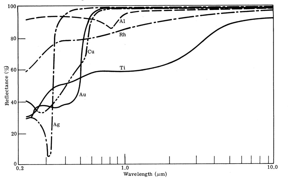
Figure 3. Reflectance of films of silver, gold, aluminum, copper, rhodium and titanium.
extended furnace operation that will heat the wall significantly, although temporarily, and destroy this type of coating. The other metallic coatings all have reflectivities near 100%, but it will make a difference how close to 100% the reflectivity is. Aluminum's reflectivity decreases somewhat in the near-infrared, with a minimum of 86% around 8 µ m wavelength. Unfortunately this is wavelength region where furnace radiation is concentrated, but Al is a convenient and inexpensive material to use at low temperatures (it melts at 660°C). The reflectivities of Au and Cu decrease rapidly below 0.6 µ m, which makes them unsuitable materials for radiation shields directly viewing very high temperature (above 1200-1500°C) sources, but most furnaces operate at lower temperatures.
Gold has been the material of choice for Phase 1 work because it has a very high reflectivity - between 98 and 99% throughout the infrared, and it has the advantage of being relatively inert. It is, of course, widely used in the space program as a radiative insulation coating on materials, but references to its use there were not found during an initial search of NASA literature. Gold is not used in commercial furnaces, presumably as a result of a combination of lack of contamination control and cost. It is common in current space furnaces, and it is used as a thin film coating in transparent furnaces as a result of its partial transparency in the visible spectrum while reflecting most of the infrared heat radiation. Gold-coated mirrors are the most common type of IR mirror in general use.
Silver is the material with the best reflectance. In the spectral region from 3-30 µ m it has an absorption of only 0.4% at room temperature, versus gold, which has an absorption of 0.6% [5]. Although this may seem a small difference, the absorption differences between gold and silver may be enough to justify the use of silver in Phase 2 as a reflector material. Unfortunately, silver has the major practical weakness in that it readily reacts with oxygen to tarnish, undergoing a major emissivity increase in the process. It is not clear how important a factor this will be in the high vacuum environment in the furnace. Normally overcoatings are considered to protect the silver, but these coatings simultaneously reduce the reflectivity of the coatings to less than that of gold, so they will not be considered in this program.
Angle of Incidence. The reflectivities discussed here are given for normal reflection, as is the usual practice. The radiation in a furnace is incident at all angles, although very little is probably present at the outer tube surface at very high angles of incidence as a result of the curvature of the surface. Data on reflectivity vs incidence angle [6] indicate that it only begins to drop at relatively high angles; reflectivity begins to be affected at angles on the order of 60 degrees, and drops rapidly for angles greater than 80 degrees. It is not clear how this will affect furnace radiation containment; probably Phase 2 experiments will be required provide information on this issue.
Surface Finish. To achieve high reflectivity surfaces, smooth surfaces are required. Smooth is defined as a surface roughness significantly less than the wavelength of the light incident on the surface. For rough surfaces high local angles of incidence can occur, as well as multiple local reflections. All of the reflective surfaces considered are coatings. These coatings are relatively thin (and thus inexpensive) compared with standard surface roughnesses, so that reflector surfaces must be polished before coating. Another issue is the surface finish of the coating itself. Some coating processes produce naturally rough coatings. Electroplating of gold was the easiest and cheapest way to deposit a gold coating, and was thus used initially. Vacuum evaporation coating is preferable.
Low Temperature Radiation Shields. For a furnace with a cylindrical geometry, radiation containment surfaces are cylindrical in the radial direction, and flat in the axial direction. The cylindrical shell is complete and simple, except for any included window. The end shields, however, must include a number of penetrations for support and heater element connections. Vacuum insulation allows the outer reflector (mirror tube) in the furnace to operate at low temperature. Furnace core temperatures of over 1000°C are expected to result in outer shell temperatures well below 100°C in the alpha prototype furnace. For this reason the material used as a coating on the inner surface of the mirror tube need have no constraints on its high temperature performance, and can be based on room temperature reflectivity data.
The difficulty of choosing a shield material for this project is shown by a simple calculation. The mirror tube has an area of approximately 2000 cm2 between the axial radiation shields. A black body at 600°C radiates about 3.3 W/cm2, so a material with a reflectivity of 98% absorbs about 130 W of power, well above the target (and experimental) performance of the low power furnace program. This means that only the best and most pure reflective materials are appropriate. Aluminum is rejected because of its mid infrared performance; only gold, silver, and copper have good enough performance. Gold and copper are weaker candidates than silver because their reflectivity does not extend to shorter wavelengths less than 0.6 µ m. At 600°C this is not a problem, since all of the thermal radiation is at wavelengths longer than 1 µ m. Detailed calculations of blackbody power vs wavelength indicate the gold will still be good enough for temperatures less than about 1500°C, which includes most current furnace work. The actual maximum temperature will be determined by when short wavelength losses become significant compared with overall absorption. At 1 µ m the reflectivity of gold is 98.1%, silver 98.9%, and their reflectivity increases slightly at longer wavelengths. The increased reflectivity of silver may almost halve the power absorption in the mirror tube, thus providing a strong motivation for its investigation during Phase 2 work. It is interesting to note that if these surfaces were at liquid nitrogen temperature, their radiant absorption would decrease by an order of magnitude.
The conclusion is that for the preliminary work here gold is an appropriate mirror material with radiant absorption in the furnace of a few tens of watts if at least one low emissivity radiation shield separates it from any high temperature high emissivity black body in the furnace core. Silver, however, has the greatest potential, if oxidation can be eliminated as a performance factor.
High Temperature Radiation Shields. The creation of a high temperature radiation shield is a very desirable goal in furnace research, because it would allow the most of radiation from the furnace core to be contained within the core. Radiant emission on the outer wall would be limited to that emitted by a black body reduced by some low emissivity factor. At present high temperature furnaces in industry use molybdenum or tungsten shields, which can only function in a vacuum environment.
A generic problem is that high temperature, very low emissivity coatings do not exist, nor do moderate cost low emissivity materials that can survive in a high temperature oxidizing environment. There are a number of natural temperature limits to coatings. Above 1000°C, thin layers diffuse into the bulk material quickly and lose their capacity to act as independent layers. Coatings will alloy with substrate material. Differences in thermal expansion combined with necessarily repeated wide temperature swings lead to high stresses and detachment of the coatings. Coatings also interact with surfaces more extensively at high temperatures, undergoing sintering, grain boundary diffusion and chemical reaction. A major problem at high temperature is that the emissivities of all metals increase with temperature.
Three possibilities for high temperature radiation shields were investigated during Phase 1; gold, molybdenum, and platinum. Gold and platinum were only considered as coatings on substrates.
Molybdenum. In the furnace industry molybdenum (Mo) is used extensively, but its surface degrades quickly under a variety of conditions. Unoxidised, polished Mo has a total emissivity of 0.03 at room temperature, increasing to 0.11 at 1000°C. Lightly oxidised molybdenum has an ε of 0.25, which becomes 0.8 when heavily oxidized. Mo melts at 2620°C. Mo is the obvious standard candidate, with a lower emissivity than tungsten (86% reflective at 2 µ m at 300°C).
Gold. Gold is not commonly thought of as a high temperature material, but its melting temperature is 1063°C. Furthermore, proprietary work at Thoughtventions has indicated that it can be attached to oxide substrates to maintain its integrity up to temperatures possibly as high as almost its melting temperature. Very thin coatings are thought to be soft enough to tolerate significant thermal expansion differences with a substrate. The absorption of gold increases significantly with temperature, increasing in the 3-30 µ m wavelength region from 0.4% at room temperature to 2.1% at 1000°C, but its absorption is still much lower than other candidates, except silver Its vapor pressure is insignificant relative to furnace vacuum below its melting point.
A basic attempt was made to test a high temperature gold radiation shield by gold coating a Hastelloy sample. Hastelloy was chosen because it has a thermal expansion coefficient similar to gold. The Hastelloy was gold electroplated by a job shop using standard techniques. An intermediate layer of nickel was added first to provide adhesion of the gold. The sample was not highly polished. Some bubbling was noted around the edges when the piece was coated. The sample (9 cm diam, 0.5 mm thick sheet) was placed in a furnace to determine when it started to degrade with temperature. The sample was not well prepared by the job shop; they had trouble nickel plating the Hastelloy supposedly because of the nickel already on in the alloy. The sample tolerated 400°C, but the gold coating had disappeared at 500°C. This phenomenon will have to be investigated in more detail in Phase 2. It is not clear whether the problem is fundamental or a weakness in the processing.
Platinum. Platinum was also considered as a high temperature radiation shield material. Platinum is expensive, but can be used economically for thin coatings. As a coating for an oxide ceramic it tolerates temperatures up to 1500°C with insignificant degradation, maintaining its reflectivity and chemical inertness. Its reflectivity is not very good in the visible (66% at HeNe wavelength), but this increases significantly at infrared wavelengths (88% at 3µ m), which is appropriate to containment of furnace radiation. It should be noted that the reflectivity of Pt is significantly improved (from 66.0% to 73.4% at 550 nm) if the deposition substrate is held at 300°C rather than at room temperature [6]. This improvement occurs for all wavelengths, but does not occur for deposition of gold or silver.
Pt is known as a "noble" metal as a result of its apparent unreactivity with most materials. Pt has a close packed face-centered cubic structure with a density of 21.45 g/cm3. Pt has strong interatomic bonds which lead to high thermal parameters; Pt melts at 1773.5 °C and boils at 4300°C. It has a specific heat of 0.0314 cal/g, a thermal conductivity of 0.1745 cal/cm2/cm/s/°C, and a coefficient of linear expansion of 9.1 x 10⁻⁶ cm/cm/°C in the range 0-100°C. The dependence of the vapor pressure of Pt on temperature is shown in Table 2. [1] Polished platinum (Pt) has an εt of 0.04, whereas lightly oxidized platinum has an ε t of 0.06 to 0.1, which increases to 0.1 to 0.15 at 1000°C. Some optical properties of Pt are given in Table 3 [7]; alloying changes ε t in rough proportion to conductivity.
In some sense these are all gross properties that are relatively easy to measure. Complications arise from the fact that most Pt is not pure, and that the impurities control many of the macroscopic properties of platinum. The hardness, strength, and recrystallization temperature of platinum depend strongly on the type and concentration of impurities. High purity Pt recrystallizes at temperatures as low as 200°C, whereas commercial Pt recrystallizes at roughly 600°C [7]. Fine grained (200-400 microns) microstructure occurs if cold deformed Pt is recrystallized at 600°C. Pt is typically annealed for 2 hours at 1400°C to recrystallize and stabilize its microstructure [8]. The behavior of Pt is sensitive to recrystallization because the primary route of chemical attack on the metal is through its grain boundaries. The strength of Pt decreases by a factor of 10 between 20°C and 1250°C.
Platinum will be a candidate as a very high temperature shield material if Mo cannot be kept clean.
Temperature Limitations on Thin Coatings. In publications on thin films, the process of thermal diffusion is implied as the reason that thin films degrade at high temperatures. Although this problem might seem fundamentally insoluble because thermal diffusion is rapid at high temperatures, the details of diffusion are complex and depend on the specific atoms and lattices involved. Certainly in some cases diffusion at temperatures above 1000°C can be slow. There has been little research in this area, and most of that is unpublished.
For thin films (less than 1 µ m thick), interdiffusion between films and substrates at 1000°C is fairly rapid, so it is unlikely that films of any material would remain pure. Deposited thin films also have a high density of vacancies and interstitials, as well as dislocations, free surfaces, and grain boundaries, all of which provide routes for rapid diffusion. In general, methods of preventing diffusion include manipulating the chemistry of both the coatings and substrates, adding diffusion barriers, and using thermal barrier coatings (to lower the temperature and thus to decrease the diffusion rate).
Diffusion processes are of three basic types: 1) metal diffuses into metal, 2) metal diffuses into ceramic, and 3) oxygen diffuses into ceramic and through ceramic into metal. The processes have different magnitudes and different temperature thresholds. Metal diffusion into ceramic is very slow compared with metal diffusion into metal because most ceramics act as ionic solids to some degree, and diffusion in ceramics is an ionic process, which is an inherently slower process than metal atom diffusion. Also the solubility of most metals in oxides is also low.
Surface Protection. A key factor in fabricating and using low emissivity radiation shields in furnace is that the surface properties must be maintained during furnace operation. The most common problem encountered in furnaces is vapor deposition. Since the outer mirror surface can be kept cool by vacuum insulation and radiation reflection, some method must be used to prevent deposition on the mirror surface by vapor driven from the furnace core. One solution is to use a quartz shield. The evaporated quartz will form a thin transparent layer on the mirror and not degrade its performance. Experiments have demonstrated that improved vacuum pumping has prevented deposition. The coatings will have to be at least as thick as the wavelength of light to have significant absorption, so coatings less than 0.1 microns will not have significant effects. Since visible light has significantly shorter wavelength than the heat radiation, probably the existence of visible overcoatings will be a good diagnostic for whether the gold has become ineffective after being coated.
Heat-Containing Furnace Windows. A small subtask has been to investigate possible heat-containing windows. Gold is the traditional material that is used in thin films to combine visible transmission with IR reflection for use in furnace windows. Many other materials have been used for what are now known as heat reflective windows, and both high visible transmission and near perfect broadband IR reflection have been achieved, driven by the mass market for solar windows. These materials cannot survive temperatures above a few hundred °C and are not usually candidates for application as furnace windows - except in this program's case where the furnace walls are cool.
Past research at Thoughtventions has shown that a number of precautions must be taken with coated windows. 1) To avoid absorption at the front (side facing furnace core) of the window, the reflective coating must not be overcoated and must directly face the radiation. Both quartz and visually transparent overcoatings will absorb significant radiant heat. 2) Minimal or no binder must be used to provide coating adhesion. By definition some of the radiation is transmitted to provide visibility - this radiation should not be significantly absorbed in the window. The standard gold heat-reflecting window uses a thin gold coating and a chromium binder. Chromium is used because of its excellent binding strength to both quartz and gold, and for its coefficient of thermal expansion that is midway between that of quartz and gold, minimizing thermal stress in the coating. Although the chromium layer is very thin (about 10 Angstroms) it is responsible for absorption of approximately 10% of the radiation that falls on the window as it passes through the binder. Absorption results from both of the chromium itself as it alloys with the gold to bind it, and the oxide, Cr2O3 (a broadband, near-perfect absorber) that forms the binding to the quartz (SiO2). Thoughtventions has developed a gold coated window that uses no binder, yet has a high strength bond.
Wavelength(microns).......Reflection(%)
0.251........................................33.8
0.288........................................38.8
0.305........................................39.8
0.326........................................41.4
0.357........................................43.4
0.385........................................45.4
0.420........................................51.8
0.450........................................54.7
0.500........................................58.4
0.550........................................61.1
0.650........................................66.5
0.700........................................69.0
0.800........................................70.3
1.0............................................72.9
2.0............................................80.6
3.0............................................88.8
4.0............................................91.5
9.0............................................95.4
Temperature(°C)........Total Emission
25.............................................0.037
100...........................................0.047
500...........................................0.096
1000.........................................0.152
1500.........................................0.191
Table 3. Optical properties of platinum.
Furnace Fabrication/Feasibility Assessment/Phase 2 Plan.
Beta Prototype Furnace. The fabricated beta prototype furnace used for testing is shown in Fig. 1. This is a resistively heated tube furnace using an open coil design. The hot zone is 5 cm in diameter and 22 cm long, bounded radially by a molybdenum (Mo) wire heater element mounted on slotted quartz rods, and bounded axially by a set of four flat radiation shields. The end radiation shields are symmetrically supported by three stainless steel tubes anchored to the first (innermost) shield. The innermost shield is 6 mm thick for support purposes; three more 0.5 mm thick shields are spaced 6 mm apart behind this shield, separated by very loose Mo wire coils. The radiation shields were initially made from highly polished aluminum, separated by thin wire coils and supported by tubes from the end caps. The three quartz heating coil supports are also supported physically by the innermost heat shield and do not extend to the end of the furnace. At a larger diameter a quartz tube and sometimes a Mo radiation shield tube were placed to enclose any vapor from either the element (Mo oxide) or the work piece. The radial outer boundary of the furnace was an internally gold-coated stainless steel tube (the mirror tube). Axially the outer boundary of the furnace was a 3 cm thick, rectangular aluminum end cap on each end. The furnace is shown with a load inside it; for initial experiments, a 5 cm diameter, thick walled alumina tube of mass approximately 80g was used.
The vacuum envelope is created by O-ring seals in the end caps at the end of the mirror tube, and by O-ring seals at axial ports at the center of the end caps through which vacuum pumping is done. Vacuum seals are also placed around thermocouple and heater element current feedthrus. Vacuum measurement ports are included in each end cap and at one location near the center of the mirror tube. Vacuum pumping is performed by a 10 cm diameter oil diffusion pump backed by a mechanical vacuum pump. Pressure/vacuum is monitored by a Varian Convectorr gauge. Pumping is done through 8 cm diameter axial ports through both end caps. The central portion of the furnace is pumped around the gap between the mirror tube and the axial radial shield OD, as well as through staggered 1 cm holes (none straight through) in the four axial radiation shields and down the center axis.
The beta prototype was designed for simple, easy, and rapid interchange and assembly of all of its components. A variety of improvements were made in the fabrication and assembly techniques of the furnace to facilitate experiments and iterations in the configuration. The furnace prototype was assembled and a variety of experiments were performed under vacuum levels that eliminate convection.
The beta prototype was used as a research tool to compare with modeling, a means of working out power reducing design details, and a means for providing an overall measure of furnace performance. As much as possible the innovations in design were added separately to determine the effectiveness, rather than having to deduce the component performance from overall furnace operating parameters.
Beta Prototype Testing. The beta prototype was operated at a variety of core temperatures with a succession of improved components. Pressure and temperature data were recorded using a computer data acquisition system so that the time response of the furnace could be examined carefully. Temperatures of the coil, the load, the end caps, 3 of the 4 radiation shields, and the mirror tube were continuously monitored using standard thermocouple instrumentation for comparison.
Furnace coil temperatures were tested up to 700°C, where the pressure in the furnace was increasing steadily. A temperature of 600°C was the baseline design of the furnace, chosen as temperature that would be useful for a wide range of materials processing experiments, yet would not cause any difficulties with high temperature materials effects that would hinder rapid and multiple furnace configuration iterations.
Low Power Testing. The approach to building a low power furnace was understood at the beginning of the program, based on extensive previous furnace work of all types at Thoughtventions. The basic design is straightforward, and discussed previous tasks. Convective heat loss is eliminated by using high vacuum. Conduction heat loss is minimized by using a small area, low thermal conductivity support structures. Radiation heat loss is minimized by surrounding the hot zone with low emissivity/high reflectivity materials. The basic beta prototype was designed using these principles. The first test of the furnace design gave 115 W of power used at a coil temperature of 600°C. This is to be compared with the exact same furnace using vacuum insulation except with a quartz outer shell that operated at the same core temperature, but used a power of almost 2 kW. These first low power experiments and their associated temperature and heat loss experiments demonstrated that the furnace and the furnace design was operating in a new regime where small effects in normal furnaces dominate the heat losses in this low power furnace. Heat loss channels on the order of 10 W become important, power measurements are more difficult, and outer shell temperatures become uncertain because the fluctuations of natural convection cooling become important. Rather than discussing the extensive sequence of experiments that led to the final results, iterations and problems with component development will be discussed, together with the results of the final low power furnace configuration.
Component Iteration. The following heat loss channel power estimations are all based on a 600°C coil temperature, which was the baseline condition of experimental tests. 1) Conduction Reduction. The discussion in Task 1 described how the hot zone supports were changed from three rods to tubes to reduce the heat conduction area. Further iterations were not attempted on this because expected heat loss was estimated to be about 8 W (ignoring thermal contact resistance at the end cap, which would decrease the estimated loss significantly), and no easily usable and cheap material with a lower thermal conductivity was available.
The current feedthrus were found to be another significant heat conduction loss channel. It was realized that this will be a fundamental problem of optimization that will be addressed in future work. The problem is that vacuum feedthrus must be both made of high electrical conductivity material to prevent excessive heating of the feedthru itself from the large electrical currents, and they must be substantial to tolerate both high currents and the structural requirements of rigidity for a vacuum fitting. The initial feedthrus were 0.64 cm diameter beryllium copper commercial units made for standard furnaces, which were changed to use 12 gage copper wire. Assuming a thermal gradient of 50°C/cm, a thermal conductivity of 4 W/cm-C (copper), and a diameter of 0.64 cm implies 60 W of heat flow and a majority of the heat loss for the 80 W iteration furnace tests. In the real case this would be reduced by contact resistance and connector thermal resistance.
2) Convection. Heat losses resulting from convection were demonstrated to be negligible. The thermal conductivity of gas at low pressure is on the order of 3-4 x 10⁻⁷ W/cm-K[4]. For a thermal gradient of 600°C over 2 cm heat fluxes are 10-4 W/cm2; for an area of 2,000 cm2 convective heat losses will only be 0.2 W, a negligible amount. Vacuum levels were improved by the necessity of reducing deposition on the mirror tube.
3) Radiation. Work was done to develop both efficient axial radiation shields and a high quality, high effeciency mirror tube. The last iteration of the mirror tube involved honing the ID of the mirror tube to about a 0.5 µ m finish, so that it was a specular reflector for thermal radiation. This eliminates multiple reflections of incident rays on the rough surface, decreasing surface absorption. The tube was then buffed and electroplated with gold again.
The end radiation shields consisted of polished aluminum plates for all but the final furnace tests, which were gold plated. They had straight through penetrations for the heater support rods, shield supports, thermocouple (one end) and the current feedthrus. There were also three staggered 1.6 cm diam holes for vacuum pumping, giving a radiating area of 65-70 cm2. Temperatures were measured on 3 of the 4 shields at one end during the 80 W test series, giving an inner shield temperature of 410°C. There was a temperature drop of about 40°C per shield for the measured shields (inner 3). Radiation from the shields, calculated based on the emissivity of Al, varied from 1-3 W total, and the pass-thru radiation was only on the order 0.5 - 1.0 W total. This is a low power and indicated that the shields were not a major heat loss factor for this series of tests, although they were critical for radiation containment. Calculations of the radiant power of the shields did not imply a constant power difference between shields, indicating that the shield temperature was also significantly influenced by conduction through the physical connections to the end caps. There was no deterioration of the Al noted at any time throughout furnace tests.
Radiation through the heater support rods was also possibly a significant heat loss channel. There is a total of 3.8 cm2 of radiating area, plus there is the likelihood that the rods act as a light pipe for radiation closer to the core, since radiation can be contained in the rods by internal reflection and emitted through the ends to the cold end cap. Bright spots were noted opposite the ends of the rods when the quartz tube was used as the outer shell. For a blackbody temperature of 600°C radiating 3.5 W/cm2, quartz transmits about 1.7 W/cm2, giving 6.5 W radiation loss at each end without a light pipe effect. Reflection off the end will reduce this figure.
Power Measurement. Measured power accuracy was poor at the low power levels that are being used. The furnace is driven by a standard SCR-controlled AC power supply, so that accurate power measurement requires a detailed integration of the voltage and current waveforms. More sensitive, isolated, phase sensitive, current and voltage sensors were purchased and installed, using a digital oscilloscope to calculate an accurate power measurement. Power measurements taken early in the program with cruder equipment were found to give 30% higher readings than the actual power.
Energy Balance/Calorimetry. Electrical power use was relatively easily measured with sophisticated equipment, but an accurate calculation of the energy balance of the furnace was extremely difficult because of the small absolute magnitudes of the heat losses and the importance thermal contact resistances, which are difficult to measure or estimate. Modeling and analysis of heat loss channel as discussed above were found to give a total heat loss that could easily be a factor of 2 in error, before the final series of experiments were done. Where possible, a single modification was made in the furnace and the temperature or power measured to try to verify individual heat loss channels.
Final Furnace Results. A number of simultaneous improvements were made to the furnace for the final tests. The mirror tube was honed, buffed, and recoated with gold. The axial radiation shields were gold plated, new lower thermal conductivity vacuum current feedthrus were put in place, and aluminum foil was put over the ends of the quartz heater support rods. The internal thermocouples were rearranged to measure the temperature of the inner radiation shield and, in a different experiment, to measure the uniformity of the temperature inside the hot zone.
Feasibility Assessment: The overall feasibility for building a low power, low mass, low cost furnace was clearly demonstrated early in the program when power levels below 100 W were reached at a coil temperature of 600°C and it became clear that careful design could be used to reach even a much lower power level. An achieved final power level of less than 80 W at a 600°C coil temperature, with further improvements predicted during future work. The furnace designs used to achieve low power are compatible with all the requirements for launch and use in space, and no high cost components are involved. Furthermore, the power levels and heat losses reached indicate that secondary support systems such as cooling, large power supplies, and heavy vacuum pumps will no longer needed for the furnace, greatly enhancing the value of this furnace design relative to present systems. Safety is also naturally improved, since outer shell temperatures are low and sequential radiation shields provide natural multiple containment shells.
The furnace and its design has many other advantages: 1) The design is suitable for high temperature use; high temperature radiation shields for the furnace have been shown to be feasible, 2) The furnace design is simple and assembly is straightforward, 3) No high cost components are used; assembly is moderate to low cost, 4) No degradation of furnace has been noted during use, 5) The furnace is easy to fabricate, easy to modularize, straightforward to automate, and easy to control using remote monitoring.
An additional issue is the potential for commercialization. The use of low power, excellent safety characteristics, and lack of need for a cooling system are major advantages for the commercialization of this device as a laboratory furnace and perhaps a production furnace. The primary drawback is the need for a high vacuum system to provide the convection insulation, and it is believed that even this drawback can be eliminated through the use of a sealed, integral vacuum jacket that need only be pumped occasionally.
Phase 2 Plan: Phase 1 work resulted in a tested beta prototype furnace using vacuum and radiation insulation to achieve very low power high temperature operation. A Phase 2 plan based on the Phase 1 prototype and its test results has been developed in detail and submitted as a Phase 2 proposal.
CONCLUSIONS
This work has demonstrated very low power operation of a prototype furnace. Vacuum and radiation insulation, coupled with low conductivity support paths provided a means to almost eliminate heat losses from the furnace, allowing elevated core temperatures to be achieved using very low power. The operating regime was found to be fundamentally different from standard furnaces; radiant heating dominates heat transfer in the furnace at all temperatures, previously small effects become important, and the furnace thermal inertia is very small. Iterations to decrease furnace power were successfully made on the furnace supports, radiation shielding, and vacuum pumping. Low and high temperature radiation shield designs were created, together with the design of a space vacuum pump that would minimize radiation loss through the pumping port in the furnace. A beta prototype tube furnace was designed, fabricated, and tested, demonstrating a steady state power of less than 80 W at 600°C coil temperature. Feasibility was demonstrated by the low power levels achieved experimentally.
NASA Applications. This furnace, and in particular the Phase 2 alpha prototype furnace will be a demonstration model to communicate the benefits of a low power, low mass, low cost space furnace. The benefits of the use of this furnace in space are that it requires no support systems and will be a minimal drain on limited space station power. Its design is well suited to safety considerations, the furnace can be made with low mass for launch purposes, and it is made from low cost components. The delivered Phase 2 prototype will be a generically useful furnace for materials processing at MSFC.
Commercial Applications: Usually furnaces require access to high power electrical facilities; these facilities must either be available or installed at significant cost, aside from the cost of the electrical power itself. The availability of a small, low power furnace would allow furnace work to be done quickly at any location, and the furnace would be easily portable. Also the ability to rapidly heat a sample is usually done at high power and limited by the time needed to heat the furnace itself. The low power furnace will have a much better time response than its competitors, an important factor in some applications.
Acknowledgements. Thoughtventions wishes to thank NASA MSFC for supporting this work under contract NAS8-99040.
REFERENCES
1. W.H. Kohl Ed., Handbook of Materials and Techniques for Vacuum Devices, Reinhold Publishing Co., New York, NY, 1968.
2. E.A. Avallone and and T. Baumeister III, Marks' Standard Handbook for Mechanical Engineers, McGraw-Hill, New York, NY, 1978.
3. R. B. Scott, Cryogenic Engineering, Met-Chem Research, Boulder, CO, (1959).
4. W.L. Wolfe and and G.J. Zissis Eds., The Infrared Handbook, Environmental Rsch Inst. of Michigan, Ann Arbor, MI, 1993.
5. I.M. Winer, "Calculated temperature dependences of silver and gold absorptions in the infrared," Appl. Opt., 17, 13, 1989 (1978).
6. G. Hass, "Reflectance and preparation of front-surface mirrors for use at various angles of incidence from the UV to far IR ," J. Opt. Soc. Am., 72, 1, 27 (1982).
7. E. Savitsky, V. Polykova, N. Govina, and N. Roshan, Physical Metallurgy of Platinum Metals, Pergamon Press, New York, NY, 1978.
8. B. Fischer, "Reduction of Platinum Corrosion in Molten Glass," Plat. Met. Rev., 36, 1, 14 (1992).