Low Loss Sapphire Windows for High Power Microwave Transmission
40 Nutmeg Lane
Glastonbury, CT 06033
EXECUTIVE SUMMARY
The Problems.Windows that transmit high power microwave (µ W) and radio frequency (RF) energy are a necessary enabling technology for plasma heating for magnetic confinement nuclear fusion devices. Window technology is marginal for microwave tubes currently being developed, whereas the level of generated microwave power that is technically feasible is continually increasing as is the frequency being used. When the transmitted power exceeds the capability of the windows (higher frequencies also usually increase losses), multiple feeds or complex windows must be used, which is very expensive for both the microwave transmission system and for the fusion vessel. Microwave transmission windows must be as thin as possible to minimize absorbed power, yet they must withstand pressure against vacuum. Other limitations on window materials are compatibility with high vacuum systems, resistance to radiation damage, and tolerance of thermal stress. The high strength and low dielectric constants of ceramics are attractive for this application, but the statistical failure of ceramics severely limits their design use. At the beginning of this program major advances in materials and/or design engineering were needed to provide large-aperture, low-loss windows for microwave transmission.
The Innovations. Specially processed and mounted sapphire windows has been shown to provide a large improvement in microwave/RF power transmission capabilities compared with current technology. By processing the sapphire surface for strengthening, using stress-minimizing designs, and minimizing thermal stresses, sapphire can be a mechanically equivalent replacement for high strength steel. In the past, sapphire has been the best material for a microwave window because of its high strength, low absorbed power and good tolerance of radiation damage. Properly mounted, strengthened sapphire windows have been experimentally demonstrated by Thoughtventions Unlimited to have a design strength that is more than 10 times larger than the current window specifications using sapphire. Further improvements that have been investigated include a surface cooled grid window concept that has been shown to have very promising power level capabilities while simultaneously being highly reliable and economical to manufacture. A quasi-optical resonant ring device has been developed at Oak Ridge National Laboratory that permits high power testing of the windows using low power, less expensive microwave drivers. This device allows testing of windows at power levels of 1.5 MW or greater using 200 kW gyrotron power sources, with gains of 25 or greater at higher frequency.
Program Accomplishments
Ultrathin sapphire microwave windows have been developed and tested in this Phase II program. Very high fracture strength (failure at very high pressures: 5-6 atm) has been experimentally demonstrated for very thin (0.5 mm) but large (100 mm diameter) windows. Polish strengthening of these disks provides part of the large performance improvement relative to the current state of the art, and stress minimization resulting from special mounting procedures provides the rest.
Polish strengthening of windows was demonstrated, and polish strengthened disks were used to fabrication a window fixture. Polish strengthened disks were purchased commercially, and polishing and inspection techniques were developed at Thoughtventions. Although reliable polish strengthening had not been obtained at the writing of this report tests indicate that continuing Phase 3 work will achieve this result.
Modeling was developed to predict the stress, strain, and deflection behavior of very thin sapphire disks. The modeling was successfully used to predict disk strain and deflection behavior. The modeling was then used to explain the widely scattered failure pressure data for extensive window breaking tests. Strengthening, mounting, and membrane effects on disk failure in response to pressure loading were explained, allowing an ultimate high power microwave window to be designed - 100 mm in diameter and 0.1 mm thick.
A resonant ring microwave power amplification device was constructed and successfully tested at low power at ORNL. This device will allow high power testing of window assemblies using only modest input power. High power testing will be performed through continued testing. A water-cooled grid window was developed, fabricated and demonstrated to be microwave transparent. The grid window was also experimentally demonstrated to tolerate 1 kW of deposited power at Thoughtventions, making it an appropriate candidate as a microwave window.
A microwave double window fixture was fabricated to demonstrate thin window power transmission capabilities and perform basic testing of the windows. The window design and the window fixture were evaluated to definitively establish the feasibility of the sapphire strengthening and mounting techniques. The fixture is ready for high power testing when it becomes available at ORNL.
The accomplishments of Phase II work are summarized as follows:
- Demonstrated more than an order of magnitude increase in window design strength compared with standard sapphire window technology.
- Developed polishing procedures for strengthening sapphire.
- Pressure tested sapphire windows to failure to validate modeling and demonstrate strengthening.
- Demonstrated sapphire disk membrane stress behavior and consequent maximum stress reduction.
- Demonstrated stress reduction in sapphire windows by modifying the support structure of the window.
- Developed modeling to predict stress, strain and deflection for all windows tested.
- Failure tested numerous windows in different mounting configurations.
- Designed, fabricated, and tested a high power microwave window fixture.
- Demonstrated microwave window fixture fabrication techniques.
- Developed a microwave resonant ring to test windows under high microwave power loads using a moderate-power source.
- Tested strengthened sapphire window fixtures for system function and microwave response.
- Developed alternate concepts for novel microwave windows, concentrating on a grid-cooled single window design.
- Developed electromagnetic, thermal and mechanical models for the grid-cooled window.
- Fabricated and tested the grid cooled window concept experimentally for cooling and microwave response.
Summary of Results
The important objective of Phase II research was achieved: to fabricate and test a prototype high power sapphire microwave window. Unfortunately, high power testing of the window was not done as a result of parallel development of diamond windows elsewhere. Specific significant detailed results of Phase I are as follows:
- Used epitaxial polishing techniques to strengthen set of sapphire windows.
- Inspected polished disks to determine if they were adequately polished for strengthening.
- Demonstrated that sapphire windows 0.5 mm thick with a 75 mm aperture could survive 5 atm pressure load.
- Measured the strain and deflection of pressure tested windows.
- Predicted the strain and deflection of pressure tested windows using modeling developed in the program.
- Predicted maximum stress level in the thin windows using this modeling.
- Failure tested windows of varying diameter, thickness, and polish were failure tested.
- Failure tested windows with varying seal to aperture diameter ratios.
- High temperature brazed a thin sapphire window into a metal fixture.
- Fabricated a strengthened sapphire double window fixture in a realistic microwave apparatus.
- Fabricated and tested a 75 mm diameter grid-cooled sapphire window under 1 kw heat load.
- Fabricated and tested a grid-cooled sapphire window double window fixture in a realistic microwave apparatus.
- Assembled and tested a microwave resonant ring for amplification and microwave response.
- Tested a strengthened, sapphire double window fixture under 1 MW microwave power in a realistic microwave apparatus.
BACKGROUND
3.1. Introduction. There are a variety of materials available for use as a microwave window; ceramics are traditionally used because of their low losses and high strength [1],[2],[3]. The weaknesses of ceramics are their inherently statistical strength and their local impurities and defects that can result in power absorption and breakage caused by thermal stresses. Single crystal sapphire is now used because of its strength and high quality, but CVD diamond windows will be a major competitor in the future.
3.2. Properties of Sapphire. Sapphire is an unusual material because it is the hardest material and has the highest melting point of any material that is commonly available. Single crystal sapphire is widely used as a result of its transparency, its superior mechanical properties, its chemical and scratch resistance, and the fact that it can be relatively easily manufactured as a grown crystal. Crystals are grown in diameters up to 15 inches, but the process is expensive as a result of sophisticated control and long growth periods. Sapphire has special optical properties in that it has a large surface reflection and is optically active as well as birefringent. The basic sapphire reference is a book edited by Balyeav [4].
Mechanical Properties - Of all of the properties of sapphire, those related to its strength are the least well defined because the failure of sapphire is statistical. Mean properties cannot be used for design work; design values must be based on the minimum possible strength; tensile strength quoted as 410 MPa (design criterion) at 25°C. Minimum strength, however, is strongly dependent on manufacturing processes.
Mechanically, sapphire is currently characterized by the optical quality of the bulk single crystal, but there are no strict standards for describing the crystal, only approximate grades. The primary reason for this accepted imprecision is the lack of correlation of identifiable defects with macroscopic behavior, except for optical clarity. Optical grading is done both because large sapphire is usually used as an optical material, and because optical testing is the simplest and easiest technique used for identifying crystal defects. Properties that change significantly with crystal orientation are an important design criterion not encountered in most material design. One example is the maximum bending stress, which increases 50% from its lowest value as the direction of stress is changed. In many systems the piece axis is typically chosen to coincide with the crystal C-axis so that the properties of the piece are symmetric around the principal stress axis.
Single crystal sapphire typically fails by a fracture process that is very complicated, analogous to brittle (versus ductile) fracture in metals. The failure normally begins at a stressed surface imperfection where a crack begins to grow through combined chemical and mechanical effects. The crack then propagates by a sequence of mechanisms that result in a rapid and total failure of the piece. Overall strength measurements are a result of this process [5] and are a statistical value depending in detail on the surface and a number of other factors. The science of fracture mechanics of crystals is not well developed at this time, although some statistical predictions can be made of strength.
Optical Properties - Optically, sapphire is an excellent material. It has high internal transmittance from 150 nm to 6000 nm in wavelength - from the far UV to the middle infrared. Its high index of refraction at visible wavelengths (1.77 vs. 1.5 for quartz) causes large surface reflection losses if uncoated. It is also birefringent, with an index of refraction that depends on both the polarization and direction of the incident light.
Electrical Properties - Sapphire is an excellent insulator, even at high temperatures, with a volume resistivity of 1014 ohm-cm. It has a dielectric strength of 480,000 volt/cm, a dielectric constant at room temperature of 9.4 for an electric field perpendicular to crystal c-axis, and 11.5 for E parallel to c-axis. It has a very low loss factor, tan δ, of about 10-4.
Thermal Properties - Sapphire responds thermally in a manner quite similar to some steels. The thermal conductivity values of sapphire are closest to that of stainless steel, while its thermal diffusivity is closest to plain carbon steel. Sapphire maintains its structural integrity up to 1600-1700°C, when it becomes increasingly plastic, until it melts at approximately 2000°C. The thermal properties of sapphire at 25°C are: Thermal conductivity (60 ° to C-axis ) = 0.065 cal/cm-sec-°C, thermal expansion coefficient = 8.40 x 10⁻⁶ per °C (60 ° from C-axis, specific heat = 0.10 cal/gm; heat capacity = 18.6 cal/°C-mole.
Thermal Stress - Thermal stress, the generation of mechanical stress due to differential thermal expansion, is important both in the manufacture the use of sapphire. This is due to comparatively large coefficients of both thermal conductivity and thermal expansion, together with anisotropic crystal properties. Residual thermal stress prevented the manufacture of large sapphire crystals until the 1940's [4]. The overall thermal stress is determined by the total temperature difference across the crystal. The controlling property is the thermal diffusivity, α = k/ρ c where k is the thermal conductivity, ρ, the density, and c, the specific heat.
3.3. Sapphire Processing. Sapphire of a desired shape is cut from grown boule by diamond saws, then final machined and polished. Polishing sapphire is very difficult because it is so hard, but good polishing techniques are available [6]. Sapphire is the third hardest material known, following diamond and cubic zirconium, with a MOH rating of 9. A standard 60/40 optical glass polish does not describe non-flat sapphire windows because sapphire can only be machined flat on a microscale for flat windows. Other shapes such as cylinders are precision machined and the undulating surface is then polished. The best sapphire polish available is an "epi-finish" that is supposedly an epitaxial surface. In this process, all of the scratches are removed by diamond dust polishing followed by a final chemical polish.
Sapphire Strengthening Research. Since the strength of a high quality piece of sapphire is determined by the condition of its surface, the preparation of that surface is crucial in an application demanding maximum strength. The process of strengthening sapphire by modifying its surface has long been known and practiced in the form of fire polishing. Fire polishing heals surface flaws but can only be used for small pieces as a result of the large thermal stresses it creates in large pieces. More recently standard optical polishing techniques have had some success in strengthening sapphire. [7]
For surface strengthening to be effective the unprocessed condition of the surface must be the determining factor for the macroscopic strength of the single crystal sapphire, and not any bulk flaws. The surface quality is most important at locations where there are large, local tensile or shear stresses are present. The surface condition at the position of maximum stress may not be relevant, however, because some other location on the surface may have half the stress but be unpolished (typically the edge of the piece). Stress distribution is determined by both mechanical and thermal loading, as well as any residual stresses in the piece itself.
The obvious techniques for removing surface flaws such as mechanical or chemical polishing have been unreliable for strengthening sapphire in the past. Improvements in the strength of sapphire have been demonstrated using: 1) Polishing, 2) Healing of surface flaws (chemically or through high temperatures), 3) Protecting the surface 4) Sealing surface flaws (solid solution layers), 5) Compressive surface layers, and 6) Crack propagation prevention (dislocation pinning). The research problem has been to discover which mechanisms are most effective for strengthening sapphire, and to find a practical technique that successfully performs the appropriate change at the surface of an arbitrarily shaped piece of sapphire. Unfortunately, practical experimental strengthening techniques almost always improve the surface through a number of the above mechanisms simultaneously. Kirchner [8] obtained compressive surface layers on a variety of ceramic materials; treatment of sapphire single crystals resulted in three-fold improvements in strength. Compressive surface stresses cause much larger tensile stresses to be required for crack growth and propagation.
An important issue associated with surface strengthening is surface protection. The environment effects the strength of sapphire through chemical enhancement of crack propagation and handling or mounting damage. Although sapphire is very hard and very scratch resistant, it is easy to microscopically scratch an unprotected surface because of the omnipresence of hard particles in the form of alumina on "sand" paper, as well as chips from the edges of the sapphire piece itself.
3.4. Microwave/RF Window Design. The discussion given below is appropriate to both microwave and radio wave (RF) transmitting windows, the only difference being the wavelength of the radiation and the dependence of the absorbencies and reflectivity on the wavelength. In the case of microwave and millimeter-wave radiation, the gyrotron is the primary means for generating high power, and it is based on cyclotron resonance coupling between microwave electric fields and electrons in vacuum. A gyrotron can produce very large amounts of pulsed (GW) or CW (MW) power output at wavelengths in the millimeter range. [9],[10] One of the important design problems in scaling gyrotrons to higher power levels or shorter wavelengths is transmitting the output power through a window in the vacuum envelope. Traditionally, polycrystalline ceramics such as alumina and BeO have been used as window materials, but sapphire (single crystal alumina - α -Al2O3) has also been used. The trend toward shorter wavelengths (higher frequencies) may make other materials more appropriate for windows. New methods of fabrication which allow higher purity or greater strength are increasing the capabilities of other materials such as Si3N4, AlN, and especially diamond.
A gyrotron operated in a CW mode places stringent constraints on window materials and design because the microwave losses in the window material result in significant temperature gradients, and only moderate gradients produce stresses that will break the window. The waveguide mode of interest for millimeter wave gyrotrons and waveguide systems is gaussian-like HE11 mode as a result of its low-loss propagation and pure linear-polarization in corrugated waveguide. The latest gyrotron designs are utilizing "flattened" electric field profiles at the output window by using mode mixtures (HE11 + higher modes) to reduce the peaking of the central power deposition which occurs in the HE11 mode. A typical current CW gyrotron window design uses two discs of ceramic placed with their axes parallel with the cylindrical waveguide. The two discs are separated by a carefully controlled amount to form a channel for coolant between the discs and to achieve resonant transmission of the microwaves through the disks. This configuration provides face cooling, which minimizes the length of the path for heat conduction through the ceramic so that the window thermal conductivity is not of major importance.
A number of desired properties for window materials can be derived from the details of their application to Fusion plasmas heating. The ceramics and the coolant should have minimum microwave loss - (ε ′)1/2tanΔ - where ε ′ is the dielectric constant in the material, and tanΔ is the loss factor. The mechanical strength should be as high as possible in order to withstand 1) the pressure forces created by the vacuum on one side and the coolant pressure on the other, and 2) the thermal stresses induced by uneven heating. The window must be an integral and perfectly vacuum tight part of the vacuum envelope. A braze joint involving a temperature cycle of the order of 800 to 1000°C is desirable. The window material must have a low vapor pressure at operating temperature (< 10-9 torr at 100°C for example), and be resistant to deterioration of any of these parameters under significant neutron radiation doses. Because the mechanical stresses which can break the window are increased significantly by temperature variations, material parameters such as Young's modulus and the coefficient of thermal expansion should be as small as possible.
Typical gyrotrons use oversized output waveguides. The guide diameter can be on the order of 6.5 to 9.0 cm, which may be equivalent to 6 to 30 free space wavelengths, depending on the operating wavelength. The window disc diameter may be 2 to 5 cm larger than the guide diameter. For proper microwave transmission each disc should be approximately an integral number of half-wavelengths thick. For mechanical purposes the disc thickness is typically about 0.25 cm. This can be one half of a wavelength (measured in the ceramic) or as many as three wavelengths, depending on the value of ε ′ and the operating wavelength.
A low value of ε ′ is desirable both because power loss is proportional to (ε ′ )1/2 and because a larger ε ′ results in a window which has a narrow frequency bandwidth. Although a gyrotron is nominally a single frequency device, a narrow window bandwidth makes it more difficult to keep the gyrotron oscillation within the desired frequency range as the gyrotron parameters such as beam voltage and current are varied of change with age. The purity of window material is also important. Inclusions can result in local hot spots, and additives that aid in forming the ceramic can increase losses even if they are uniformly dispersed. Surface cracks can result in significantly shorter window life. [11]
In the context of these parameters, sapphire is among the best materials available except for its relatively large coefficient of thermal expansion and thus thermal stress susceptibility. Commercial sapphire has a loss factor close to 10-4, small amounts of impurities, and high strength. Its dielectric properties have been studied in detail (e.g. [12]), and, its losses drop dramatically at cryogenic temperatures [12]. Finally it has the advantage of a low susceptibility to radiation damage [3], an important issue for long term use on reactors.
The desirable properties for the window cooling material include good heat transfer, such as high boiling point and heat capacity and low viscosity. Low ε ′ and microwave loss are useful but not as important as the heat transfer properties. Coolants that have proven useful include FC-75 (a fluorocarbon product of 3M Corp.) and tetradecane.
Sapphire Window Development and Testing.
The effort of this work was devoted to fabricating ultrathin strengthened sapphire disks and to accurately model the stresses in the disks. The work can be divided up into three parts: 1) polishing development, 2) stress modeling, and 3) window pressure testing. The design clear aperture diameter for the Phase 2 program is 90 mm. This is the appropriate size for the apparatus used for high power testing at ORNL.
Sapphire Fabrication. There were two sources of sapphire for the project: Meller Optics (Providence, RI) and Union Carbide (UC - Crystal Products Division, Washougal, WA). The bulk sapphire for the Meller windows was supplied by Crystal Systems (Salem, MA), whereas UC grows their own sapphire. Bulk sapphire is grown in boules using the controlled heat exchange technique.
A wide variety of sapphire samples were fabricated for the program. Aside from polishing samples, over 50 sapphire windows were included in the test program, varying in diameter from 12.5 mm to 102 mm, and in thickness from 0.33 mm to 2.0 mm. Window fabrication techniques varied as well. The worst surface finish used was the standard 80/50 optical polish, whereas the pieces with the best polish had a nearly epitaxial surface. Bulk material was usually the best quality, defect free sapphire, characterized by Crystal Systems as HEMEX, but some HEMLIGHT, samples were included as exceptions (where noted). Samples were primarily R-plane, with a few C-plane samples included for comparison and result verification. A full list of samples is given in Appendix A.
Polishing Development. A proprietary polishing process has been specified by Dr. Bates. The polishing process itself is highly proprietary, but some of the variables involved can be discussed. The polishing process takes place between two machine-driven, counterrotating surfaces. The sapphire disks are firmly but temporarily mounted on one surface; the other surface, known as a lap, provides the abrasive surface for the polishing process. The type of lap used, the rotation speed, the pressure, the grading of the diamond grits for each polishing step, the time for each step, and finally the parameters of the chemical polishing colloidal silica solution (acidity, concentration, temperature, refresh rate, etc.) are all important parameters for the overall process. There are also other practical issues associated with fabricating very thin disks: the possibility of breakage during handling, and the tendency of material to warp during machining, and the difficulty of removing polishing debris.
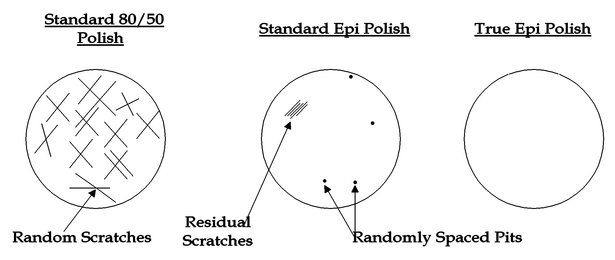
Figure 1. Illustration of stages of polish in the strengthening process.
Figure 1 shows the generic progression in polish that occurs during the polishing stages that are necessary to achieve polish strengthening. The standard 80/50 Scratch/Dig optical polish is shown on the left. The scratches that are shown are caused by polishing with diamond grit. For sapphire, the next level of polish beyond this type of standard optical surface is a nominal 5/10 polish that is termed epi because the finish is so close to an epitaxial surface. These surfaces are usually characterized by a surface roughness that is on the order of nanometers. For the purposes of strengthening, however, isolated flaws that are not a factor for overall roughness are responsible for the crack initiation that greatly reduces macroscopic strength. These must be removed totally to achieve a strengthened piece.
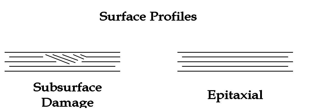
Figure 2. Illustration of subsurface damage in a piece with an epitaxial surface.
Even the removal of all surface scratches is not a sufficient condition for reliable strengthening. Subsurface damage must also be removed. Figure 2 shows schematically a cross section of a surface that has an epitaxial surface but subsurface damage. Subsurface damage is usually created by anomalous and extreme damage during rough polishing or cutting that is usually only detectable using acid etch procedures. In this program SEM inspection is used to perform non-destructive examination of sub-surface damage. It is believed that final chemical polishing masks subsurface damage by dissolving and redepositing sapphire so that some surface defects are actually filled in or covered over, but not removed. This phenomena is unimportant for optical purposes, but is again critical for strengthening.
At the end of the Phase 1 program there were apparently two commercial sources (Meller Optics, and Union Carbide) of polish strengthened sapphire, neither of which were aware that the sapphire that they were providing was sometimes strengthened. Strengthening is masked by (and is often responsible for) the normal statistical variation in the strength of sapphire. The amount of strengthening is ultimately determined by failure pressure, but SEM inspection has been used to demonstrate an adequate degree of polishing for strengthening.
A number of supposedly epitaxial disks were purchased from Union Carbide while polishing development took place as a joint effort between Thoughtventions and Meller Optics. The Union Carbide disks provided windows for the bulk of the testing of the program, as well as for the final prototype window fixture. SEM inspection indicated that the wafers had few enough defects that they should be polish strengthened, but the disks were not perfect epitaxial surface as advertised (and used in the electronics industry). Failure testing of these disks indicated that most, but not all, of the disks were strengthened. Union Carbide only makes a few sizes of disks, and only one side of the wafers is in some sense guaranteed to be epitaxial; the other side has a best effort polish. This means the wafers are mounted with the epi side on the low pressure side for maximum effectiveness.
At the beginning of the Phase 2 program, Meller Optics prepared of a set of 2.5 cm diameter thin disks to test polish strengthening using polishing procedures that were apparently identical to those that had been used in Phase 1. Failure testing of these disks showed no statistical evidence of strengthening. SEM inspection was then performed, showing that the disks had significant numbers of surface flaws, and were thus not truly epitaxial surfaces. Two problems were discovered, one fundamental and one a technical detail. The fundamental change in sapphire processing parameters compared with that of Phase 1 was that much thinner windows were polished. The thinner disks were required both for failure testing and for eventual use as microwave windows, but the change in thickness forced changes in the polishing processes using the same equipment. The fundamental problem was that the material was so thin that polishing debris could not be carried away from the between the polishing plates that were now very close together. This debris degrades the edge polish and sometimes the central polish. This was not the case for the thicker disks polished in Phase 1.
This problem was solved in the short term at Meller by beginning with larger (32 mm OD) disks, then cutting off the outer edges after polishing. At the same time, thicker 5 cm diameter disks from stock were repolished specifically to demonstrate strengthening. Two of the 5 cm disks were failure tested, and shown to be unstrengthened. SEM inspection of all of the newly polished disks again showed an inadequate polish. The problem was discovered when Meller examined their polishing process. They found that their supplier of polishing pads had changed the formulation without telling them.
At this point it became necessary to perform some detailed polishing research. Since Meller was working more than full time on production they could not pursue this research. They were able to donate two old and cannibalized polishing machines to Thoughtventions for refurbishment and use to achieve the program and Phase 3 goals. The manuals for these Strasbaugh machines were obtained from the manufacturer. The gearing and bearings from the machines were removed for cleaning and bearing replacement where needed, the necessary replacement parts were ordered and installed, and the machines returned to working order.
Extensive polishing tests were performed and discussed with Meller. Much of the success of polishing is an art rather than a science. Experiments indicated that multiple polishing attempts with diamond grit were inherently unsuccessful; the polishing had to be set up and run in one attempt. Furthermore, material removal using chemical polishing was not done at Meller, only superficial polishing, a process that inherently cannot remove subsurface damage. Higher material removal rate chemical polishing is being pursued at Thoughtventions, iterating with SEM inspection to develop a final polish strengthening process. Although some strengthened samples have been obtained (enough to provide strengthened windows), a reliable polish strengthening process had not been developed at this writing. This work will be continued in Phase 3; Thoughtventions still believes that it can develop an appropriate polishing technique.
Stress Modeling. For preparation of the Phase 1 proposal and during the Phase 1 program experimental testing showed that the failure pressures observed during hydrostatic testing of thin sapphire windows were well above that predicted by the standard theory of bending disks.
The standard and accepted analysis of the stress for microwave window disks is that of a uniformly distributed load on a thin disk [13]. The loading diagram is shown in Fig. 3 for a disk function of radius a, thickness h, and the load q. The maximum stress σmax at the center of the disk is then
σ max = 3(3 + ν)qa2/8h2
where ν is Poisson's ratio. For sapphire, ν = 0.25, and the equation can be rewritten as:
σmax = 1.22qa2/h2
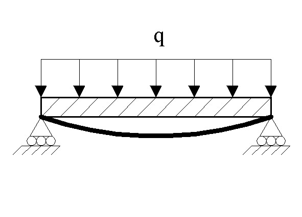
Figure 3. Loading diagram for an edge mounted thin disk.
Initial failure testing indicated that the window loadings observed were too high to be explained by either the standard strength of sapphire (tensile strength = 420 MPa) or even the strengthened sapphire (by a factor of 3 - 4) if the standard theory was used and R was taken to be the radius of the aperture for hydraulic tests as is normally the case. There was no question that either some other stress-reducing mechanism was taking place or that the above modeling for the maximum stress in the disk did not apply in some respect. The flexing thin disk model is well established and has been tested for accuracy for use with standard sapphire microwave windows in the past.
This contradiction between actual and predicted failure loading was resolved during Phase 2 work. The detailed modeling and the comparison with results will be discussed below. Before this is done the physical effects that are occurring which make the standard flexing thin disk theory inappropriate will be discussed.
The primary changes to the standard disk modeling that will be described here are the different boundary conditions at the edge of the disk and the addition of membrane effects. The flexing disk model discussed above assumes that the edges of the disk can move freely both radially and in edge surface angle. It also assumes that the center deflection of the disk is small - less than half the thickness of the disk. For the thin sapphire windows of this program both of these assumptions are not correct, and a more complete theory must be used.
The major change required in the simply supported disk model for the relatively early thick disk tests is that of the edge boundary condition. The first hydraulic tests of 1 mm thick 2.5 cm diameter disks performed in an earlier NASA program [14] used O-rings to seal the window. These O-rings were necessarily placed at a larger diameter than the window aperture, so that the O-ring would be contained and function properly. As a result, the actual loading diagram of the window was thought to be as shown in Fig. 4, for an aperture radius a1 and a sealing radius a.
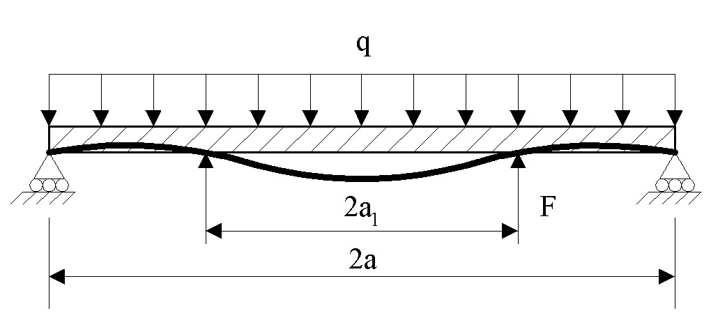
Figure 4. Loading diagram for an edge mounted thin disk.
The window was assumed to be in contact with the surface at the O-ring. For larger radii the net loading on the window disappears as a result of equal pressures on both sides of the window. The complete load diagram indicates that the disk has a significant bending moment imposed at the aperture as a result of the loading at a larger radius than the aperture.
This was interpreted as a cantilevering effect. The loading outside the aperture will counterbalance the pressure inside the aperture (transmitted moment) and lead to an overall stress reduction at the center of disk where the stress is at a maximum. This reduces the maximum stress on the disk for the same pressure if the radius of the disk is increased beyond the radius of the aperture.
Using a simple area balance of the loading inside and outside the aperture radius, a new effective loading area was derived for calculating the maximum stress at the center of the disc. If the outer radius of the pressure loading is q and the radius of the aperture is ai, then the fractional decrease in effective loading area would be approximately 2 - (a/ai)2. For a reduction in loading by a factor of 3, a 6 cm aperture window would be sealed at a 10 cm radius. This decrease in load would allow a factor of (3)1/2 or 1.7 times thinner window. Strengthened windows would lead to a similar reduction in window thickness, and the effects would be additive. The cantilevering effect, added to the strengthening, appeared to accurately predict the experimental results in the NASA program.
Standard flexing disk theory can analytically describe the response of a disk for the case of a fixed edge (location and slope), or a disk with moments imposed at the edge. These boundary conditions do not usually correspond to actual experiments, since perfect clamping requires large forces, and edge moments cannot usually be measured. Equation 1 may also not be appropriate because the maximum stress may no longer be at the center of the disk. The fully clamped edge condition does, however, provide a limits for the maximum stress in the disk for linear theory. At the center of a thin flexing disk with a fixed edge and uniform load Eq. 1 becomes
σ r=0 = 0.47qa2/h2
with higher stresses at the edge of the disk:
σ r=a = 0.75qa2/h2
Even at the edge, the maximum stress in the disk has been reduced by 40% for the clamped-edge boundary condition compared with the free edge boundary condition. The boundary conditions for a disk under pressure sealed with an O-ring is somewhere between these two limits. The actual boundary condition for this case is closer to the edge clamped boundary condition for an O-ring diameter that is much larger than the aperture diameter, but closer to the simply supported boundary condition for an O-ring diameter that is not much larger than the aperture diameter. As will be shown below, the difference in the predicted peak stress in the disk between these two boundary conditions changes significantly in large deflection theory.
Membrane Effects. During testing of thinner (< 1 mm), large diameter (> 50 mm) disks even larger reductions in peak stress were deduced from failure strength, compared with the cantilever effects of thicker disks. Research into the modeling of very thin large disks led to the realization that membrane effects were important.
Membrane effects describe the case where the disk stretches rather than bends. Figure 5 shows the differences in the deflection and stress for the two cases. Figure 6a shows the case for a standard flexing disk where the deflection is small compared with the thickness. This is the fundamental assumption for standard thin disk stress prediction, and leads to the formulas that are currently used for designing microwave windows. The side nearest the load is under compression, whereas the side away from the loading is under tension. For an edge supported disk the maximum stress depends on load, radius and thickness as:
σ max proportional to q(a/h)2
Figure 6b shows the case for a membrane where the deflection is much larger than the thickness, and bending moments are unimportant. In this case the entire thickness of the disk is in tension, so that the tensile stress necessary to balance the loading can be spread over the entire thickness of the disk. For an edge supported membrane the maximum stress has a quite different dependence on disk parameters:
σ max proportional to E1/3q2/3(a/h)2/3
In the membrane regime the maximum stress in a disk increases much more slowly with disk radius, and it is somewhat dependent on the Young's Modulus, which effectively measures the thickness contraction as the membrane stretches. Sapphire is much too stiff for bending moments to be totally neglected, so modeling the stress in very thin sapphire windows involves some combination of membrane and bending effects.
Large Deflection Theory. Given that the standard theory of thin flexing disks is inadequate because it does not include membrane effects, research was performed to find a tractable model that could be used to predict the response to loading of very thin sapphire disks.
The general theoretical treatment of thin circular plates is based on the following assumptions: (1) The plate is flat, of uniform thickness, and of homogeneous isotropic material, (2) The thickness of the plate is not more than about 1/4 of its least transverse dimension, (3) All forces - loads and reactions - are normal to the plane of the plate, and (4) The plate is nowhere stressed beyond its elastic limit.
For a thin plate under transverse loading, bending (flexural behavior) and stretching (membrane behavior) can both occur at the same time. Pure bending behavior is such that the mid-plane undergoes only out-of-plane deflection, which is small by definition. The relationships of stress and deformations with the transverse loading are linear and this type of behavior is governed by the small-deflection theory. The typical limit on central deflection for pure bending modeling to be valid is that the deflection be less than half the thickness of the disk.
As the disk deflection increases beyond half the disk thickness, the material in the disk begins to stretch as well as bend, and membrane effects become significant. For purely membrane behavior, the plate does not deform out of its plane. The deformations are confined to the directions parallel to the plane of the disk only, and are constant throughout the thickness of the plate for all the layers. When the normal maximum deflection of a plate reaches the order of the thickness of the plate, the membrane action becomes comparable to that of the bending. For larger deflections membrane effects dominate. [15]
The theory for disk behavior that is generalized to include membrane effects is called the large-deflection theory of plates, and it is valid even when the deflections are equal or larger than the plate thickness, although the deflections must still be small relative to the other dimensions (the diameter) of the plate. The stresses and deflections vary in a non-linear manner with the magnitude of the transverse loading.
Large deflection modeling is described in detail in a classic text by Timoshenko [15], which forms the basis for the work presented here. It describes the more complete theory of an edge-mounted circular plate where the deflection at the center of the plate under load can be on the order of the plate thickness or larger. Large deflection theory is inherently non-linear and the theory is complex enough that the work done in this program has used approximate solution techniques [15]. The general problem of the response of plates to loading is analyzed in terms of strain, displacements, forces and strain energy. Stress is a derived quantity based on equations that determine the deflection of the disk over its surface.
The transition from linear to non-linear behavior occurs over a narrow range in the load parameter, qa4/Eh4, where q is the load (Pa), a is the disk radius, E is Young's modulus, and h is the disk thickness. For a clamped disk, if the load parameter has a value of about 6 the linear theory over predicts the deflection and the stress by about 20%. In this case the deflection to thickness ratio, w0/h, is about 1. Linear theory becomes increasingly inaccurate for load parameters larger than this, but is a good approximation when the load parameter is smaller. Note that whether a disk is in the non-linear regime depends on the load, q, as well as the radius to thickness ratio, a/h, and the properties of the material through E.
An equivalent alternative description is that each specific material that acts like a plate (vs. membrane) limited in its deflection by its specific failure strength and its stiffness. These factors are characterized together in the stress parameter, σ a2/Eh2. Large deflection theory (20% error from linear theory) should be used when the stress parameter is greater than about 3. Whether the disk is thin enough that pressure loading causes a large deflection is not only determined by its thickness relative to the supporting radius but also by both its stiffness over the unsupported span and its inherent strength to withstand both stretching and bending. A thinner, stiffer disk can behave in a linear manner described by bending theory, whereas a thicker, less stiff disk can behave in a non-linear manner. For a specific material E is fixed, as is its failure stress, σ f. Thus for a specific disk where a and h are known the stress parameter must be less than σfa2/Eh2 for the linear theory relating load to stress to apply. The limiting value of the stress parameter based on failure strength determines whether the membrane forces important in large deflection theory can be achieved under sufficient load, and how far into the large deflection regime the disk is operating when it fails.
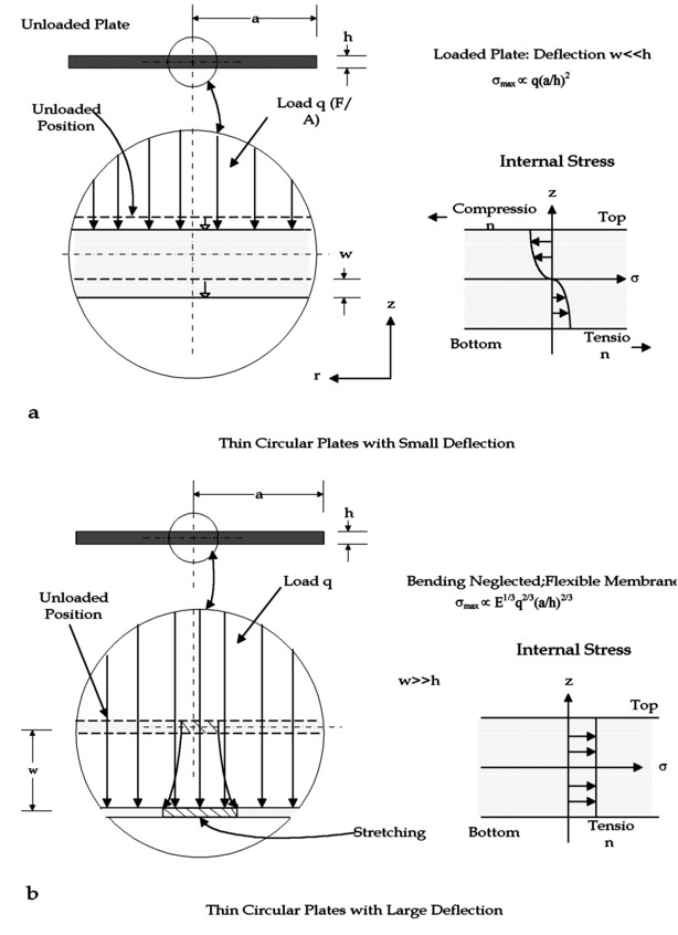
Figure 5. Load/deflection diagram for membrane effects.
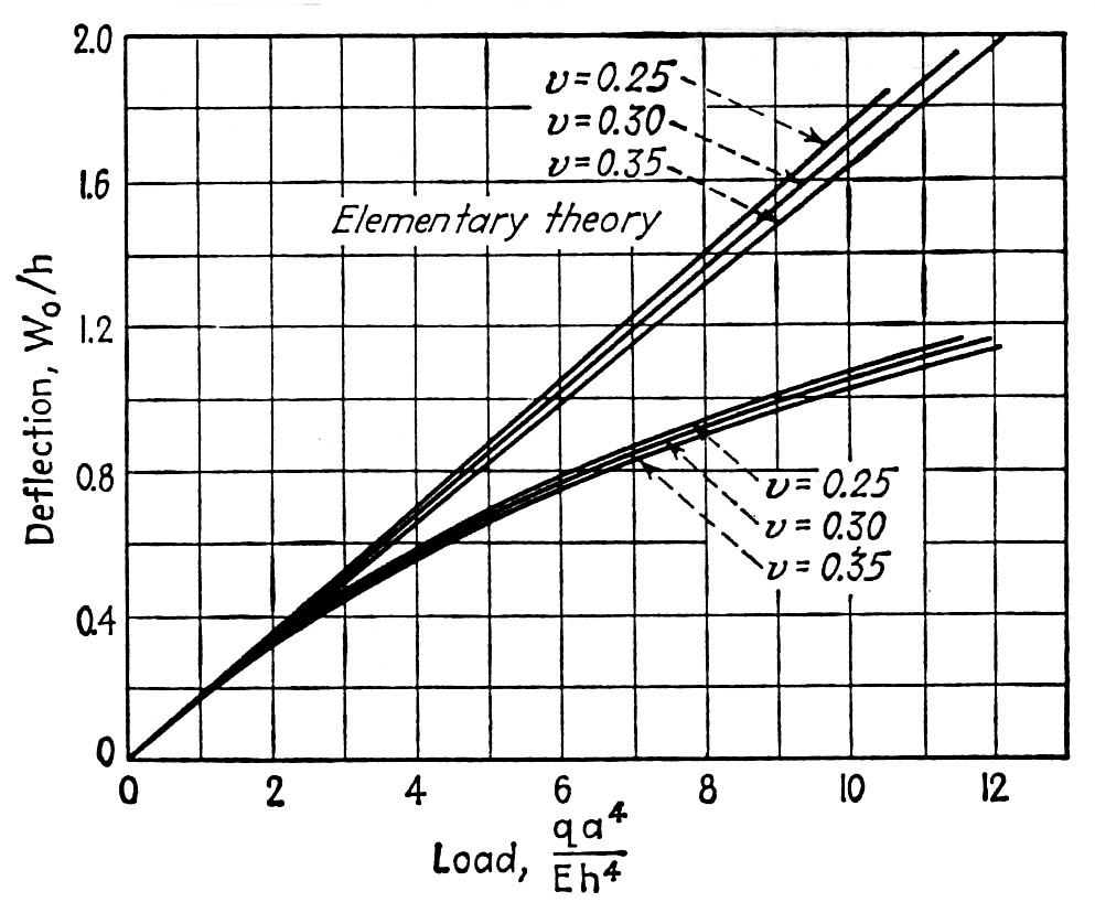
Figure 6a. Deflection vs. load factor for linear vs. large deflection theory.
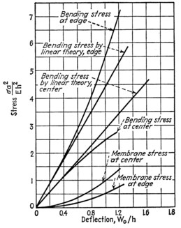
Figure 6b. Stress vs. deflection for linear vs. large deflection theory.
The divergence between the predictions of linear theory and those of large deflection theory are shown in Figs. 6a and 6b. [15]. Figure 6a shows how as the load factor increases, the actual deflection increases much more gradually with load than as predicted by linear theory. Figure 6b allows the difference in theory to be defined in terms of stress. Figure 6b shows that for small deflection membrane effects are negligible and the linear theory is accurate. At deflections (w0/h) of 0.5 membrane stresses become significant and the linear theory breaks down. Note that the graph in Fig. 6b is deceptive in indicating that the non-linear, large deflection theory predicts larger stresses than that predicted by the linear theory. Figure 6b shows that for the same deflection the sum of membrane plus bending stresses are greater than that predicted by linear theory. Figure 6a, however, shows that for large deflections the large deflection theory predicts much lower deflections for a given load, and thus lower stresses.
As an example of the behavior of a disk made of a common strong material, the degree to which steel is in the large deflection regime can be calculated as follows. AISI-SAE 1020 hardened plain carbon steel has a tensile strength of 620 MPa, and a Young's Modulus of 200 GPa. The parameters applicable to the present microwave window case are that the disk cover a 100 mm aperture and support a minimum of 2 atm (1 atm plus a safety factor of 100%). Based on linear flexing disk theory (Eq. 1), setting σ max = σ f, and a = 50 mm, a steel disk with h = 0.9 mm will fail at 2 atm pressure. The radius to thickness ratio, a/h, is 55, and the stress parameter is 9. This means that under these conditions near failure steel is in the large deflection regime, but not by a large margin. Since the steel disk is operating in the large deflection regime, the linear theory implies that a larger thickness is needed than is actually necessary. The true minimum design thickness leads to a higher stress factor and behavior that is farther into the large deflection regime after each iteration. The immediate conclusion is that most optical materials will never operate near the large deflection regime, since they are weaker by orders of magnitude than steel and thus they will require a much greater thickness to support the pressure and they will have a much smaller stress factor.
Single crystal sapphire is not a typical optical material, with a standard strength not much lower than the steel described above, since the average failure strength for sapphire with a standard polish is approximately 420 MPa.
For a sapphire disk (E = 345 x 109 Pa) under similar conditions as that specified above for a steel disk, a sapphire disk would be 1.2 mm thick assuming linear theory. The stress factor would be about 2, which is on the borderline of the large deflection regime.
The fact that standard sapphire mounted in the usual manner is on the borderline of the large deflection regime, is critical to the effort described in this report to create very thin sapphire microwave windows. For most materials failure strength is a fixed, prespecified property of a given material. For sapphire the failure strength varies by a large amount as a result of both the statistical nature of the failure of sapphire as a ceramic, and as a result of polish strengthening. By using polishing strengthening and appropriate edge mounting techniques, sapphire windows can be designed to function well into the large deflection regime, so that linear theory greatly overestimates the necessary disk thickness. The disks can be made much thinner because stresses are distributed throughout the window by membrane forces.
When membrane forces are significant, the response of a disk to loading is fundamentally changed, as is disk design. Linear theory predicts that the design thickness of the disk depends on the square root of the loading, which is a weak dependence. For linear theory, a factor of 2 reduction in load, which is a major decrease, only allows a factor of 1.4 reduction in disk thickness. In the large deflection regime, an increase in failure strength by a factor of 2 (by polish strengthening, for instance) can result in a factor of 3 thinner disk, which is a major reduction in terms of microwave absorption. The influence of membrane effects may modify the degree to which sapphire can be polish strengthened, however, since this strengthening relies on the fact that surface flaws limit the inherent strength of sapphire. When the peak stress in the sapphire is more uniformly distributed throughout the thickness of the disk rather than at a surface, polish strengthening may be less important.
Another peculiarity of the present effort is the degree to which failure strength and edge boundary conditions affect the engineering behavior of the disks. In most cases, for relatively thick disks the central stress is not dependent on edge conditions because the deflection at the edge of a strong disk is negligible. Edge boundary conditions are well known for their effect on the stress in mechanical systems, and these effects become important for very thin sapphire disks where edge deflections become significant under load.
Quantitative Prediction. Accurate theoretical prediction of the stress and deflection for the real case of the cantilevered sapphire window is not possible analytically, but must be done computationally. The primary engineering goal of modeling is to predict the failure stress to an accuracy of 10 to 20%. As an approximation to large deflection theory [15] the deflection w0 at the center of the disk is given by the equation:
w0/h + A(w0/h)3 = B(q/E)(a/h)4
where w0 is the (maximum) deflection at the center, and A and B are constants determined by the boundary conditions on the disk. The constants that are given in Timoshenko for this equation, and used for the calculations presented below assume a Poisson's ratio, ν = 0.3, rather than ν = 0.25 for sapphire, but the corrections for this difference should be small. There are four fundamental edge conditions given:
1) Plate clamped, edge immovable.
2) Plate clamped, edge free.
3) Plate simply supported, edge immovable.
4) Plate simply supported, edge free.
These different conditions lead to very different predictions of the stress in the disk, as in the case of linear theory. Clamping the edge provides substantial moment at the edge of the disk when it is loaded. Making the edge immovable forces the disk to stretch as it deflects, increasing membrane effects.
Figure 7 shows linear theory and large deflection theory predictions for a 1 mm thick sapphire disk of approximately 100 mm in diameter. The solid straight line bounding all of the curves at the top is the linear prediction of stress versus pressure loading. The two large deflection theory, simply supported boundary condition cases diverge from this linear theory near 1 atm of pressure. Note how well these calculations agree with the estimations about how close this size sapphire disk would be to the large deflection regime at this pressure. For both clamped boundary conditions the linear and large deflection theories do not diverge very much at the pressures shown. The linear theory for the clamped boundary conditions is not shown; it is a straight-line tangent to the low pressure data for the large deflection theory using this boundary condition.
Figure 7. Large deflection and linear theory predictions for a sapphire disk with thickness 1.0 mm and radius 44.6 mm mounted at its edge.
Assuming standard sapphire is used with a failure stress of 420 MPa, a sapphire disk of these parameters would fail at 1.75 atm according to linear theory, but in reality it would fail at just over 3 atm for the simply supported, edge immovable case, a 70% increase in loading. Strengthened sapphire would result in even larger loading differences between the linear and large deflection predictions. For only a 50% strengthening of the sapphire the failure load would increase from 2.5 atm for linear theory to 5.5 atm in the large deflection, simply supported, edge immovable case. This is a 120% increase in load carrying capacity, a large factor. The difference increases as the disk thickness is decreased to minimize the thickness for failure at a specific loading, so that the disk behavior is farther into the membrane regime.
It can be seen that the edge free and edge immovable boundary conditions lead to very different predictions in the large deflection theory. This is because constraining the edge radially forces the disk to stretch, and this effect enhances membrane effects. In many practical cases an immovable edge is a better approximation to experimental conditions than is a free edge because the disk extends well beyond the aperture. The sapphire material beyond the aperture acts to constrain the material at the aperture edge to so that it cannot move radially. Any kind of brazing at the edge of the disk also tends to make the edge boundary condition closer to an immovable edge.
Cantilevering the disk by making it significantly larger than the aperture and sealing the outer edge tends to approximate the clamped edge boundary condition. This technique uses pressure on the disk area that is outside the aperture to counterbalance the pressure inside the aperture. The counterbalancing forces are transmitted to the center of the disk by moments at the disk aperture, which is exactly the boundary condition of a clamped edge. A clamped edge is a special case of cantilevering where the pressure on the outer part of the disk is sufficient to keep the disk flat against the support at a radius equal to and larger than the aperture radius. Less pressure allows the disk to lift off of the surface, so that the actual boundary condition for a cantilevered disk is somewhere between the clamped and simply supported case. The effect of cantilevering relative to the case of a simply supported disk can be assessed by examining the case of the clamped boundary condition for a disk with the same aperture. The larger and thinner the disk is, the better will be the approximation to the clamped boundary condition. It is also important to note that just as the cantilevering does not provide enough force to provide true clamping, it also reduces the stress at the aperture edge, which is very high for the fully clamped case. In the fully clamped case the stress is a maximum at the edge of the disk.
Window Testing/Modeling Comparison. The above discussion presents a complex description of the behavior of a thin sapphire disk where it is difficult to predict failure stress from failure pressure and where it is seen to be difficult to predict the precise boundary conditions in a real experiment. This complexity makes analysis difficult but is appropriate for practical use, none the less. The description of an aperture-mounted disk with varying edge boundary conditions arises from what is the most common and simple experimental/industrial practice for mounting windows.
Testing Apparatus. Hydraulic pressure tests were done to measure window performance and to mimic the actual use conditions of a microwave window. Pressure testing to failure is straightforward to do. The pressure gauges used to monitor failure pressure are accurate to a few percent. The mounting configuration is an industry and commercial standard. Translation of the tests to commercial practice are direct within the statistical failure of the sapphire. Correlating experimental pressure testing results with the standard characterization of sapphire is much more complex. The standard failure strength of sapphire is generally given as a minimum tensile strength with considerable statistical variation. The maximum tensile stress in a disk during a pressure test is difficult to derive from modeling in the presence of membrane effects and mixed boundary conditions.
A hydraulic pressure failure testing facility shown in Fig. 8 was used to test the behavior of sapphire windows in response to pressure loading for this program. The fixture consists of two conflat flanges bolted together and sealed by knife edges in the flanges that simultaneously deform a copper gasket. Pressure is supplied by a medium pressure hydraulic hand pump. Two 2% accuracy pressure gauges with ranges from 0-0.4 MPa, and 0-2.8 MPa, measured pressure that was recorded with a computer data acquisition system. The windows are sealed to the flanges using an O-ring in an appropriately sized groove. A segmented O-ring placed between the upper flange and the window is used to force the window against the O-ring for initial sealing before pressurization.
Figure 8. Schematic of hydraulic pressure failure testing fixture and deflection measuring apparatus.
Different size windows can be tested in the same fixture by fabricating a flange with stepped recesses with different size O-ring grooves as shown in Fig. 9. A total of three separate fixtures were used to test windows ranging from 12.5 mm to 100 mm in diameter. For the largest windows the central deflection measurements of the
Figure 9. Sapphire disk pressure testing flange.
windows were confused by the simultaneous deflection of the windows and the O-ring before the window came in contact with the flange. The recesses at the center of the flange were deep enough to assure that the flexing disks would not come into contact with the bottom of the flange during pressure testing. The deflection of the disk being tested was always measured to verify that no contact occurred. A small axial hole at the center of the flange assured that the window was holding pressure and provided access to measure disk deflection as well as a means for connecting strain gauges attached to the bottom of the windows.
Central deflection was measured using an inductive displacement sensor (Microstrain, Inc.). This device has a maximum non-linearity of approximately 0.4% its 8 mm full scale. It has a resolution of a few microns. Strain was measured at the center of the disks during pressure tests using standard resistance strain gauges with an accuracy of a few percent. Time response was not important for either measurement device.
Windows Tested. During the Phase I and Phase II programs approximately 75 windows of diameters between 12.5 mm and 102 mm were tested in a variety of ways. Window thickness varied from 0.33 mm to 3 mm.
More than 30 windows were tested to failure (see Table 1). Most of the windows were high quality sapphire; no bulk defects were observed in any of the windows. The major variable in window preparation was window polish. Surfaces varied in preparation from a matt finish to an almost epitaxial surface. Most of the windows tested were R-plane for reasons of cost, although some C-plane windows were tested.
Testing Techniques. Four basic types of testing were done. The primary test was failure testing; increasing the pressure on edge-sealed windows until they failed, measuring the failure pressure. Central deflection and central strain measurements were performed specifically to validate modeling. Measurements were recorded by a computer data acquisition system. The final type of testing was polish inspection, either using optical techniques or SEM imaging.
Data Analysis. Analysis of window failure pressure, central deflection, and central strain measurements was performed to achieve the following goals:
Table 1. Windows Failure Tested.
Diameter(mm)................. # Tested
......12.5..........................10
......25.............................. 9
......50.............................. 2
...... 75..............................3
.....100............................... 7
1) To show that large deflection modeling accurately predicts the experimental behavior of sapphire disks under pressure loading.
2) To determine the increase in the failure strength of sapphire that results from polish strengthening relative to the standard quoted strength of sapphire.
3) To predict the thickness reduction that could be achieved for a sapphire disk as a result of membrane effects compared with the standard window design that assumes a simply supported thin flexing disk.
4) To predict the maximum thickness reduction that can be achieved for a sapphire disk using polish strengthening, cantilevering, and membrane effects compared with the standard window design that assumes a simply supported thin flexing disk.
The major important physical effects that control the behavior of very thin edge mounted sapphire disks under pressure loading are:
- Membrane effects (in addition to bending).
- Failure strength of the sapphire.
- Real edge boundary conditions.
Since all of these effects interact with each other, it is difficult to isolate each effect and assess how it affects the behavior of the disk under load. This work leads to the belief that large deflection theory provides a guide for analyzing these effects. A matrix of experimental tests that varies the polish, edge boundary conditions, and disk thickness relative to diameter has been used to achieve the stated analysis goals.
Strength Testing Without Membrane Effects. The discussion of data will begin with the analysis of the data where membrane effects do not dominate the stress performance of the disk. There are two available data sets to discuss for this case. The first data set was taken during work on a previous NASA contract. Tests were performed on 25.4 mm diameter, 1 mm thick, C-plane disks in a hydraulic fixture where the disks were O-ring sealed in the same manner used in this program. The sealing radius was 11.7 mm and the aperture radius was 9.5 mm. Disks with two types of polish were tested; a standard 80/50 polish, and an "epi" polish provided by INSACO (Quakertown, PA). The data is shown in Fig. 10. The average failure pressure is approximately 8 MPa for the standard disks, and 26 MPa for the selected epi polished disks.
Disk behavior during pressure testing is dominated by both polish strengthening and the edge boundary condition at the aperture diameter. The experimental and theoretical difficulty is to establish the magnitude of both of these effects separately. The separation is made more difficult because of the statistical nature of the strength of sapphire.
An exact analytic solution to the cantilevered disk problem has not been found during this program, except for the case of a specific radius ratio where the edge of the disk is in the plane of the aperture. The equation for the stress at the center of a simply supported disk is given in Eqs. 1 and 2, whereas the analogous equations for the clamped case are given in Eq. 3 for the central stress, and in Eq. 4 for the edge stress. The peak stress in the simply supported disk is at the center, whereas the peak stress for the clamped disk is at the edge and is approximately 60% less than that for the simply supported case. In some sense these conditions represent extreme specifications of bending at the edge of the disk - no edge bending for the simply supported case, and maximum bending forces for the clamped case. Where membrane effects are negligible, increased cantilevering decreases the stress at the center of the disk, which is also the maximum stress in the disk. At the aperture radius the stress for the cantilevered case is less than that of the clamped case until the amount of cantilevering is such that the slope at the aperture becomes horizontal. For cantilevering in normal configurations, the load that can be added beyond the aperture is limited by the condition that the outer edge comes in contact with the flange surface. This condition occurs at a radius ratio of approximately 0.7 and results in a reduction of the peak stress by approximately a factor of 2. Smaller radius ratios will give a smaller stress reduction, whereas larger ratios will give about the same reduction because the added load is absorbed in the contact between the outer edge and the flange.
Calculating the failure pressure of the 25.4 mm diameter, 1 mm thick disks using linear simply supported disk theory based on the standard 420 MPa strength of sapphire and the aperture radius gives a failure pressure of 3.8 MPa. The seal to aperture radius ratio is approximately 0.7. Assuming a stress reduction of a factor of 2, the predicted failure load is about 7.5 MPa. This is reasonable agreement with the data, although the number of samples is not large. The polish strengthened disks indicate an average strength increase of more than a factor of 3. It
Figure 10. Failure pressure of a set of 2.5 mm diameter, 1.0 mm thick sapphire windows with a standard 80/50 polish and a nominal epitaxial finish.
Figure 11. Failure pressure of a set of 25.4 mm diameter, 0.51 mm thick sapphire windows with a standard 80/50 polish (Tests # 1-4) and a nominal epitaxial finish (Tests # 6-10).
should also be noted that the set of four high strength windows was selected on the basis of a lack of flaws and then tested. Although there are only 4 samples the probability of choosing 4 high strength windows from a standard set is almost zero. These windows were not selected based on failure strength results.
A series of pressure failure tests (Fig. 11) were done on a similar set of 2.54 mm diameter, 0.51 thick disks during the development of polishing in Phase 2. The aperture and seal radii were approximately as in the NASA tests. These disks are still thick and small enough so that membrane effects are negligible. Figure 12 shows the failure pressure of 9 disks, four with a standard polish, and 5 with what was hoped to be an epi polish. Since the aperture is approximately the same as the NASA tests, and the thickness 0.5 times as much, the failure pressure would be expected to be approximately a factor of 4 less, or about 2 MPa, with strengthened disks 3-4 times as strong - or 6-8 MPa failure pressure.
One item of note is the large variation between weakest and strongest sample, a factor of 18.6 variation in strength. Given that the strengthened disks are often apparently not strengthened, the specially polished disks were inspected under the SEM. This inspection showed that while the center of the disks were polished without defects, most of the area of the disks were poorly polished, with the polish deteriorating toward the edge. In fact, near the edge the polish was not far different than the standard disks. The lack of strengthening was therefore explained by the lack of good polish, where the one high-strength case was probably just polished enough to achieve the strengthening effect. The cause of the problem apparently is associated with the extreme thinness of the disks - the polishing plates are so close together that the polishing debris is swept onto the edges of the disks again and proper polishing is not possible. It is important to note that the standard samples are normal commercial samples that would be obtained by an industrial sapphire user with no knowledge beyond the size specifications of an optical window.
There is no question that the highest failure pressure disk broke at a much higher stress level, because the breaking stress determines the size of the broken pieces. The broken pieces of this disk was much smaller in average size. The immovable edge cases do approach each other for large loading, differing by a small amount at 19 MPa. The predicted stress is 3 GPa, which is 5 times the nominal strength of sapphire. This seems high, but not impossible. Apparently the much higher pressure results from the change in slope of the stress vs. load curve - a much higher percentage change in load is required to cause the same percentage change in stress compared with changes at lower values of load. Presumably the strengthened disks entered into this less sensitive regime and allowed much higher loads to be tolerated. It thus seems that the 2.5 cm disks happened to be in a transition region of disk behavior, which accounts for the large variation in failure pressure.
Another relevant set of data was taken by testing 12.5 mm diameter, 0.5 mm thick disks. A set of random orientation, standard 80/50 polish windows were failure tested, together with a set of Union Carbide disks of the same dimensions cut out of a 100 mm diameter disk. The aperture radius was 3.85 mm, whereas the seal radius was approximately 5.2 mm, giving a radius ratio of about 0.75, and thus leading again to a stress reduction of about 30%. Calculating the failure pressure of the disks using simply supported disk theory based on a 420 MPa strength of sapphire and the aperture radius gives a failure pressure of 6.0 MPa. Accounting for the 30% stress reduction implies a failure pressure of about 8.5 MPa. Strengthening by approximately a factor of 3 would give a failure pressure of 27 MPa for epi polished disks.
The failure data is shown for the 12.5 mm diameter disks is shown in Fig. 12. The average failure pressure for the standard disks is 12 MPa, whereas the average failure pressure for the epi disks is 23 MPa.
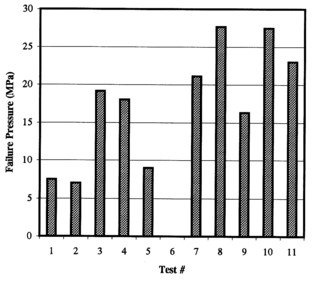
Figure 12. Failure pressure of a set of 12.5 mm diameter, 051 mm thick sapphire windows with a standard 80/50 polish (Tests # 1-5) and a nominal epitaxial finish (Tests # 7-11).
For these tests the variation in strength was approximately a factor of 4. This is a small sample, and confusion is added to the standard sample by not placing any constraint on either the quality or the orientation of the standard disks. The disks had no observable defects, either by eye or through crossed polarizers. The epi samples were best quality sapphire, but they were cut from a larger disk, which may have introduced flaws. Furthermore, it is known that the large disks have more defects at the edge than at the center - sample 7 was taken from the edge.
The apparent disagreement between the theoretical prediction and the average of the standard disk experimental data is explained by postulating that some of these disks have been strengthened, and some of the epi polished disks weakened, both by the chance inclusion or exclusion of weakening flaws. If this were the case the lowest failure pressure values for the standard polish would be expected to agree with the theory for the unstrengthened sapphire, as well as the highest failure pressure values matching theory for the epi polished disks. The data indicates that this is the case. The failure pressure varies by a factor of 4 for all of the disks, which is a very large variation in strength. The strength of the 80/50 polish disks varies by a factor of 2.7; the epi disk strength varies by a factor of 1.7.
The degree of variation in the failure strength data does not allow the prediction of standard failure strength, unless the minimum strength results are used. Given the large variation, quite a few more tests would have to be done to verify that the minimums are indeed typical minimums. For the purposes of engineering, the minimum strength would have to be used, which, for sapphire, is usually given as approximately 420 MPa in tension at room temperature. The variation in these results makes it very difficult to use for supporting any modeling calculations.
Strain/Deflection Testing. Other properties than strength, such as Poisson's ratio, ν , and Young's modulus, E, are well known and accurately specified for sapphire. This means that although the failure strength cannot be readily predicted, the strain (stress) and deflection of the disk in response to load are much more accurately known. As a result, stress/strain and central deflection measurements provide a much more reliable test and support of large deflection modeling.
A complication in correlating experimental stress/strain and deflection vs. load with large deflection theory was found to be the O-ring sealing. O-rings require compression to seal, and most of the window pressure testing was done without any significant static clamping on the window. High-force clamping would seat the O-ring, but it would also lead to high stresses at the aperture rather than the distributed stresses sought to optimize window performance. Experimentally, the windows begin pressurization seated and sealed against the O-ring, but not in contact with the flange face or aperture. As the loading built up the disk would both deflect at the center and the outer edge would move toward the flange face. At some load the disk would come in contact with the aperture. For lower loads the disk would act as a simply supported disk, supported at the O-ring radius. For higher loads, the disk would act in a cantilevered manner, closer to the edge immovable and clamped boundary condition based on a disk with a radius equal to the aperture radius. This effect will be discussed with respect to the detail test results discussed below.
Deflection measurements were performed on 2.5 cm, 5.0 cm, 7.5 cm, and 10.0 cm diameter disks. Strain gauge measurements were made on 5.0 cm, and 10.0 cm diameter disks. Because of the progressive seating of the O-ring, the disks are described as 1) initially edge mounted and simply supported at the O-ring diameter until it deflects enough to come in contact with the flange at the aperture, at which point it becomes 2) an edge mounted disk supported at the aperture diameter with an immovable edge (constrained by the material beyond the aperture) that is progressively more clamped as the pressure increases and the force on the part of the disk beyond the aperture increases.
Experimental results best agree with large deflection modeling in the case where the disk is purposely clamped into the flange by adding a spacer ring between the flanges. Clamping in not perfect, because the primary clamp between the flange must be the conflat knife edge that forms the pressure seal. Figures 13a and b show the results of strain and displacement testing on a 100 cm diameter clamped disk. The aperture radius is 44.6 mm. Figure 13a shows the central displacement vs. load. The experimental results agree closely with the large deflection model for the clamped, immovable edge case. The prediction of the linear model and some other boundary conditions for the large deflection model are also shown for comparison. Central deflection for the clamped, edge immovable case is approximately 1/3 of what it would be for the simply supported case. Figure 13b shows the central stress for the clamped, edge immovable case, which also agrees well with the model. As expected the agreement improves at higher loads. At a load of 1 atm. the central stress is reduced by a over a factor of 3 compared with linear theory, but it must be remembered that the stress is higher at the aperture. The strain and derived stress experimental results appeared to be less reliable than the central deflection measurements, which were a simpler measurement.
A very different test case of the displacement and stress theory is the data for a 100 mm window supported and sealed near its edge, with an aperture radius of 44.6 mm and a seal radius of 46.5 mm. Figure 14a shows the displacement data, together with the simply supported and clamped immovable edge cases predicted by the large deflection theory. The experimental data measures the displacement of the window that includes the compression of the O-ring. The window is approximately 0.35 mm above the flange surface at zero pressure. At 2 atm loading the disk is cantilevered at the aperture, so that the true central deflection is 1.55 mm - 0.35 mm, or 1.2 mm, in close agreement again with the simply supported, edge immovable data. The experimental data and theory for stress vs. load is shown in Fig. 14b. The measured stress is what would be expected of a disk that began to be loaded at the O-ring diameter and approached large deflection theory for a disk the same diameter as the aperture at higher loading.
Extensive displacement data was taken for 75 mm, 0.43 mm thick sapphire windows that were soldered onto copper cups that formed one half of a standard double-disk microwave window fixture. The copper cups had a nominal 64 mm ID. The soldering process bowed the disks toward the high pressure side by approximately 0.15 mm at the center due to the larger contraction of the copper and solder relative to the sapphire. After the joint had hardened the copper contracted more than the sapphire, bowing the sapphire away from the copper cup at the center. This added an effective cantilevering preload to the sapphire. Under 1 atm vacuum, the deflection at the center of the disk was 0.21 mm, giving a total of 0.36 mm central deflection in response to 1 atm pressure. Large deflection theory predicts a central deflection of 0.42 mm for a clamped, immovable edge 64 mm diameter disk. The soldered disk must bend the copper at its edge, as well, presumably accounting for the reduced total deflection.
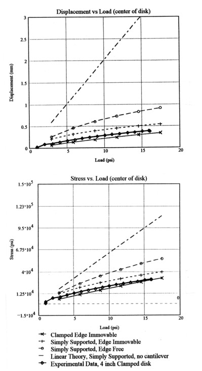
Figure 13. Large deflection modeling compared with experimental results for a 100 mm diameter thin clamped sapphire window: a) central deflection vs. load, and b) central stress vs. load.
Stress and deflection measurements were also made on a 50 mm diameter, 33 mm thick disk. The displacement and stress theory and data for a 50 cm window with an aperture radius of 20.9 mm are shown in Fig. 15 together with the stress and displacement data. Figure 15a shows the displacement data together with the simply supported, simply supported edge immovable, and clamped immovable edge cases theory predictions. The experimental data measures the displacement of the window that includes the compression of the O-ring. The window is approximately 0.5 mm above the flange surface at zero pressure. At 2 atm loading the disk is cantilevered at the aperture, so that the true central deflection is 8.4 mm - 0.5 mm, or 3.4 mm, in close agreement with the simply supported, edge immovable data. The experimental data and theory for stress vs. load is shown in Fig. 15b. The measured stress at high loading approaches the simply supported, edge immovable data as expected. At lower pressures the disk behaves as if it were simply support, edge free with a diameter equal to the O-ring diameter. Since this is a significantly larger diameter than the aperture diameter, the stresses are higher. The 50 mm disk measurements are thus fully consistent with large deflection theory.
Deflection data was also taken for 25 mm diameter, 0.51 mm thick disks. The disks had an aperture diameter of 19 mm and a seal diameter of approximately 24.6 mm. Deflection data was again very close to the simply supported, edge immovable case.
All of the data together strongly support the use of large deflection theory to predict the behavior of the O-ring sealed windows. The edge immovable, simply supported boundary condition based on the aperture diameter seems to be the appropriate input parameters for the theory for the testing procedures and disk parameters used in this program. This boundary condition does not imply high edge stresses, so it should give good predictions of the maximum stress in the disk. It is not clear whether the edge immovable boundary condition represents the true physical condition of the disk, or whether the combination of partial clamping and extended material makes this condition hold as an average condition. It does seem appropriate to use the edge immovable, simply supported boundary condition of large deflection theory based on the flange aperture to predict failure stress from failure pressure measurements. This will allow some conclusions to be reached about polish strengthening and the statistics of the sapphire failure.
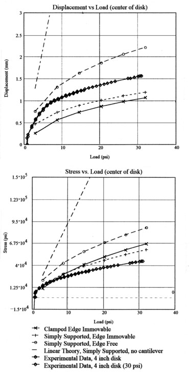
Figure 14. Large deflection modeling compared with experimental results for a thin unclamped 100 mm diameter sapphire window: a) central deflection vs. load, and b) central stress vs. load.
Strength Prediction. Large deflection theory solves for the deflection of a disk as a function of loading and boundary condition. Stress is a derived parameter of this solution. Pressure failure testing gives a pressure loading at which the disk fails. By definition, the disk always fails when its failure strength has been exceeded. If large deflection theory is accurate, it should be able to predict the failure strength of the disk given the loading. Conversely, given the failure strength of sapphire, the theory should allow an accurate derivation of the load at failure. An exact correlation of prediction and experiment is not practical as a result of the variation in the failure strength of sapphire from piece to piece. The effects of polish strengthening broaden the failure strength range of sapphire.
There are three classes of disks tested for this program. The Union Carbide disks will be defined as Class 1 disks. These disks have the highest quality polish and are most likely to be polished strengthened. The standard 80/50 polish disks are defined as Class 3. These disks are characterized only by the fact that they meet optical standards for polish, and they are not expected to be significantly polish strengthened. The disks that have undergone non-standard polishing at Thoughtventions form an intermediate Class 2, which presumably consist of some disks that are polish strengthened, and some that are not. Experimental testing has demonstrated that even the Class 1 disks are not reliably strengthened.
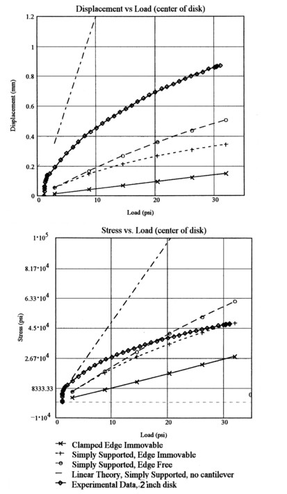
Figure 15. Large deflection modeling compared with experimental results for a thin unclamped 50 mm diameter sapphire window: a) central deflection vs. load, and b) central stress vs. load.
The expectation of large strength variations in disks of the varying classes is best shown in the test data on the 25 mm diameter disks shown in Fig. 11. In this data set that includes samples from Class 1 and Class 2 the failure pressure varies by a factor of 19 as a result of one apparently unusually strong sample.
There is another piece of data that confirms the accuracy and relative magnitude of the failure pressure results for disk testing. The strain energy that is contained in the disk at the time of failure pressure is released during fracture. The higher the strain energy the smaller the pieces that result from the fracture. Figure 16 shows this phenomenon for a 2.5 cm diameter, 0.5 mm thick disk. The 100 mm diameter disks were tested with an adhesive backed paper attached to keep the pieces in place after failure. For the strengthened disks the 100 mm diameter disks failed such that the largest remaining pieces in the aperture were only a few mm in length. The fracture size results were totally consistent with the failure pressure results: disks that failed at low pressure broke into large pieces, while disks that failed at high pressure broke into very small pieces.
First the Union Carbide Class 1 disks will be considered. The tests on this material included sets of 12.5, 50, 75, and 100 mm diameter disks. One characteristic of the dependence of stress on load in the large deflection theory is that the central stress increases much less than linearly with load. This means that a small increase in strength will lead to a much larger increase in failure loading. At the same time, a small variation in failure load will imply approximately the failure stress.
A reanalysis was done for Phase 1 tests based on the results of large deflection modeling. Table 2 presents a summary of the failure testing results from Phase 1, plus the stress,σ fc, at the center of the disk predicted by large deflection theory when the disk fails. In Table 1 dw is the window diameter, tw is the window thickness, HPS denotes high pressure side, LPS denotes low pressure side, da is the window aperture diameter, ds is the diameter of the pressure seal. Disks with different polishes on one side were used because one-side polished disks are 30% cheaper, and it was originally thought that the cheaper disks would be
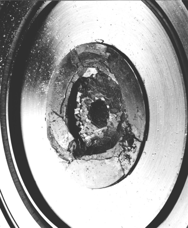
Figure 16. Photograph of a broken 50 mm diameter. 0.33 mm thick disk after failure testing.
adequate because the maximum stress would be only on one side, the side not facing the pressure. The two 100 mm diameter disks (Tests # 4 & 5) failed at approximately 5 and 6 atm. Large deflection theory indicates that the radial stress at the aperture was approximately 400 MPa, implying that the overall performance of the disk was limited by the strength of the matt polished side rather than the epi polished side. The stress at center of the disk on the low-pressure side was approximately 800 MPa, implying that the polish strengthening was at least a factor of 2.7.
Table 2. Phase 1 Sapphire disk pressure failure testing results.
| Test # |
dw (mm) |
tw (mm) |
Polish HPS |
Polish LPS |
da (mm) |
ds (mm) |
Pf (kPa) |
σ fc (MPa) |
| 1 | 51 | 0.33 | Matt | Epi | 30 | 45 | 849 | 750 |
| 2 | 51 | 0.33 | Epi | Matt | 30 | 45 | 483 | 500 |
| 3 | 51 | 0.33 | Matt | Epi | 30 | 45 | 1104 | 900 |
| 4 | 102 | 0.525 | Matt | Epi | 89 | 95 | 625 | 800 |
| 5 | 102 | 0.525 | Matt | Epi | 89 | 95 | 525 | 800 |
| 6 | 51 | 0.33 | Epi | Epi | 42 | 45 | 475 | 700 |
| 7 | 51 | 0.33 | Epi | Epi | 30 | 45 | 2650 | 1400 |
The data on the 51 mm diameter disks leads to similar conclusions. Tests #1 and #3 provide the same evidence for failure of the matt polish, since the stress at the edge was approximately 400 MPa. Test #2 indicates failure at the center, again as a result of the matt polish. Tests # 6 and #7 give information on the failure strength of an epi-polished disk; test #6 indicates a factor of 1.7 strengthening, whereas test #7 indicates a factor of 3.3.
One added complication is that it was later discovered that only one side of the Union Carbide disks is guaranteed to be an epi polish; the other side is a "best effort" epi polish. Which side was which was not recorded for the Phase 1 tests. Phase 1 tests thus provide 6 data points for a polish strengthening of approximately a factor of 2 or more.
76 mm Disks. A set of Union Carbide 76 mm diameter disks finished were also pressure tested. All of the 76 mm diameter disks were tested after being brazed or soldered. This process first involves an aggressive metalization process of the sapphire to allow the joining metal to wet and bond to the sapphire.
Two of these were the disks that were soldered onto a microwave fixture during the Phase 1 program. The testing of these disks is also discussed in Task 2. Both of these disks were 76 mm diameter disks with a 63.5 mm aperture, and they both broke under 1 atm pressure. These disks had a matt finish on the high pressure side and an epi polish on the low pressure side. One disk broke immediately; the other broke after extensive deflection testing. The process of soldering to the copper fixture resulted in a central deflection of the disk of 0.15 mm toward the high pressure side. This deflection implies an equivalent loading of about 1/5 of an atm, which should not significantly affect the stress at the center of the disk. However, if the solder joint and its supporting copper provided a clamped boundary condition for the disk at the aperture, then the stress on the matt side of the disk would be approximately the normal failure stress of sapphire and this would explain the failure of the disk. The stress at the disk center would be far below what would be expected from the strengthening effect of the epi polish.
Using the large deflection theory for the case of a 32 mm radius, simply supported, immovable edge, the measured deflection at 1 atm pressure of approximately 1 disk thickness agrees with modeling. The predicted stress at the center of the disk is about 200 MPa, but a similar stress level is predicted to exist on the top of the disk at its edge. This is very close to the failure strength of matt polished sapphire, which is presumably why the disk broke. The theory thus agrees fairly well with this data. The shape of the deflection vs. radius is also well predicted. It should be noted that the linear theory predicts a factor of 6 higher stress.
A third failure test also used a 76 mm diameter disk with a 63.5 mm aperture, but in this case the disk was polished on both sides and face brazed to a thin kovar ring that had a 89 mm OD and 63.5 mm ID. This disk broke at a pressure of 3.7 atm, for which the predicted strength at the disk center is about 600 MPa, implying a 50% strengthening. This may imply that the brazing process has a negative impact on the strengthening.
3) 50 mm Disks. Four 50 mm diameter, 2 mm thick disks were specially polished by Meller Optics to try to obtain strengthening disks. A previous polishing attempt by Meller produced the disks whose failure test results are presented in Fig. 12. Whereas these disks were superior to standard disks, they were not consistently strengthened. SEM inspection showed that some of the disks were scratched. Analysis of the polishing process indicated that the thinness of the disks resulted in a close spacing of the polishing fixtures that caused debris to enter the polishing interface and rescratch the disks. To avoid this problem 2 mm disks were polished.
Two disks were pressure tested in the standard hydraulic fixture, measuring the disk deflection with the apparatus illustrated in Fig. 5. Deflection is accurately measured to an accuracy of 0.01 mm, but O-ring compression is always a complicating factor. Both disks failed at a relatively low pressure: 2.9 and 1.9 MPa. Modeling predicted that standard strength sapphire would fail at approximately 3.4 MPa, so these disks showed no indication of strengthening. Possible causes of the low failure pressure include inherent weakness of R-plane disks, residual stress in the disks, and inadequate polish. Further work will have to be done to resolve this problem. The measured deflection was comparable with O-ring compression, so that true disk deflection was small, consistent with theory.
One of the disks was then inspected in the SEM; again showing problems with the polish at the edge of the disk. In this case there were no residual scratches as seen with the smaller disks, but there were many defects at the edge, decreasing with the distance away from the edge. The damaged region extended to between 2.5 to 5 mm from the edge. This accounted for the poor pressure results and forced Thoughtventions to begin its own internal polishing development.
Minimum Thickness Design As a result of the work of this program, a series of effects can be taken advantage of when designing minimum thickness sapphire windows. The first effect is polish strengthening of the sapphire. The second effect is that when the disks are thin enough so that their deflection under load is large compared with their thickness, membrane forces lead to a reduction in the maximum stress at the center of the disk relative to only bending forces. The disks can then be designed to be thinner to achieve the same central stress as was the case without membrane effects. The final effect is that some bending from loading of the part of the disk beyond the aperture is transmitted to the center of the disk reducing the maximum stress there, again allowing a thinner disk to be designed to achieve the same maximum stress in the disk. In terms of stress modeling, the boundary conditions on the disk are designed to minimize the peak stress in the disk, while the thickness of the disk is specified such that the peak stress in the disk is equal to the failure strength of the disk divided by some safety factor. Some care must be taken with the use of larger disks that have loading beyond the aperture, since the design-limiting peak stress may be at the aperture radius rather than the center of the disk.
To design a disk to tolerate a specific pressure, the primary concern is the maximum stress in the disk. The location of the maximum stress is usually either at the radius of the edge of the aperture upon which the disk is mounted or at the center of the disk. If the disk is not clamped in any way, the stress is low at the aperture radius and high at the center of the disk. This is rarely true in a practical case, since the disk must somehow be sealed to the aperture to allow it to be pressure loaded, and the seal provides some degree of clamping. The stress at the aperture edge is much more difficult to predict than the stress at the center of the disk.
One implication of the higher sensitivity of design thickness to failure stress and load for large deflection theory is that the design values for these parameters must be optimized as much as possible. This is difficult to do in terms of the failure strength of standard sapphire because this strength is statistical, as it is for most ceramics. However, since sapphire (and ceramics) are less sensitive to fatigue, disks can be tested to eliminate the weakest samples, and the surviving disks can be used based on their actual tested strength. In the case of a standard double window for a high power microwave tube the pressure loading on the window can be minimized by not operating the cooling liquid at pressures above one atm, and by designing a pressure relief system so that overpressure cannot occur. If the disks are pretested for strength and the cooling system cannot exceed 1 atm operating pressure, then common engineering safety factors can also be reduced, perhaps from 100% to 50% or even 25%. Since the windows are pretested they must possess at least some margin of safety themselves, which would supply some of the engineering safety factor beyond that specified.
The key point is that the factor of 3 extra strength gained from the polishing allows the sapphire to be thin enough at low pressures (5 atm) to function partially as a membrane rather than as a flexing disk. A flexing disk is in compression on one side and in tension on the other, whereas a membrane is in tension at the center throughout the disk. As a result, the membrane can distribute the stress over the whole thickness, greatly reducing the peak stress compared with a flexing disk and allowing a much thinner disk to be used for the same design pressure. No other material except diamond is strong enough to be in the membrane regime, making strengthened sapphire unique as a low-loss material for µ W windows. This says nothing about the additional reduction in absorption losses for sapphire at cryogenic temperatures, where it also becomes somewhat stronger.
Comparison with Current Practice. The baseline case is an edge-mounted sapphire window with a thickness that has been calculated to be half the failure strength of standard sapphire, based on standard bending thin disk theory. Assume that the design strength of sapphire is the accepted commercial design strength of 420 MPa, and assume throughout the discussion that a safety factor of 2 is used. Take the design pressure to be 1 atm - supporting a standard atmosphere against vacuum. This is not the usual design condition for sapphire microwave windows, because they are usually cooled with a low microwave absorption pressurized fluid (5 atm). Pressurization is not necessary, however, and the calculations will show that the benefits of designing for a lower pressure far outweigh the engineering effort necessary to reduce the pressure. If the disk is assumed to be thin and edge mounted with a small deflection under load, then the standard thin flexing disk theory (Eq. 1) predicts a design thickness:
t = [1.22(2w)/σ f]0.5a
This increases the failure strength of the disk by approximately a factor of 3, and thus, by the standard theory, the disks can be made (3)1/2 times thinner and still support the same pressure with the same safety factor.
The failure testing results show very high failure pressures for such thin windows compared with current practice. A standard sapphire microwave window in a 7.5 cm aperture is about 2.5 mm thick [16], supporting 2 atm pressure with a safety factor of 2. This would imply a failure pressure of about 4 atm.
For a sapphire disk with a 44.6 mm aperture radius that was designed to fail at a stress of 800 MPa under a 2 atm pressure, the disk thickness predicted by large deflection theory would be approximately 0.1 mm thick. A standard 100 mm microwave window with a thickness of 2.7 mm can nominally survive almost 500 kW of power, so the new window should be able to survive many MW if it can be made and tested.
Based on the experience of CPI a comparison with state of the art microwave windows can be made. Their 110 GHz double disc sapphire window is expected to be useful to 500 to 600 kW CW. This window fixture uses 3/2 wavelength thick (2.72 mm) sapphire disks with a FC-75 pressure of about 4 atm absolute. An appropriate improvement based on this research would be a 0.1 mm thick or 1/20 wavelength thick, which will certainly be easier to frequency match.
Thermal Design. One of the weaknesses of sapphire is its sensitivity to thermal stress as a result of a combination of a thermal expansion coefficient and thermal conductivity that are both relatively high. Thermal loading of a microwave window is different from the usual application where the heating is external, because the heat is deposited throughout the bulk of the window, primarily at its center where the radial maxima of the electric field occurs for the primary microwave modes (e.g. a gaussian mode).
Thermal stress has been a key factor in limiting the use of sapphire in general, and in particular in the case of sapphire microwave windows. The power limitation on current double sapphire windows cooled with FC-75 is a result of the boiling of this coolant followed by local thermal stress fracture where the coolant boils. The heat is generated either by direct microwave heating of the sapphire or by local arcing.
Thermal Stress Testing. A series of thermal stress tests were performed on the thin sapphire as a result of other work presented at the SPIE conference on Window and Dome Technologies and Materials [17]. The work presented in this paper concerns thermal stress in missile domes as a result of aerodynamic heating. The military has sponsored a great deal of research in an effort to solve this problem. A simple test of thermal stress resistance that is often used is to quench a hot sample in water. The lowest sample temperature that still results in fracture after quenching is a measure of the resistance of a material to thermal stress. The conference report [17] includes this type of data for sapphire. For a 2.5 cm diameter, 2 mm sapphire thick disk with a standard polish quenching at 170°C results in no fracture, whereas quenching from 200°C does cause fracture, and quenching from 250°C causes much more severe fracture. This is a worst case scenario of thermal stress, because quenching causes the outside of the sapphire to be in tension and the inside to be in compression, so that the unpolished edge of the disk provides a weak surface from which cracks can propagate.
Thermal stress in sapphire has been the subject of a great deal of work at Thoughtventions. Tests have shown that failure caused by thermal stress varies greatly with the geometry of the piece as well as with the direction and magnitude of the temperature gradient (higher to lower temperature) relative to the piece geometry. Sapphire normally has a much higher compressive strength than tensile strength (except at moderate temperatures around 800°C), and a much lower surface strength than bulk strength. As a result, the same temperature gradients that would result in fracture caused by a surface in tension and internal compression would not harm the part if the gradients were reversed in sign to cause compression at the surface and tension in the interior of the part. Simple tests were done to confirm this and to confirm the standard quench tests.
The basic parameter that describes thermal stress is the product E α Δ T, where E is Young's Modulus, α is thermal diffusivity of the material, and Δ T is the temperature difference in the material. For sapphire E = 345 GPa, and α = 6 x 10⁻⁶, so if a failure strength of σ f = 400 MPa is assumed for sapphire, a temperature difference of approximately 200°C would result in thermal stress failure. This compares closely with the water quench tests discussed above.
The most serious problems that are caused by thermal gradients are usually the result of transient conditions such as quenching. A heat pulse applied to a surface cannot be instantaneously conducted away into the material, so, for a short time, the applied heat raises the surface temperature to unusually high values. After a period of time defined by the material's thermal properties, the thermal energy in the hot surface layer is conducted away and the surface temperature drops. The peak surface temperature occurs when the heat input to the surface is balanced by the heat conducted into the material. The higher the material thermal conductivity is the lower will be the maximum surface temperature, given a fixed heat input. The heat input to the surface is in turn controlled by the heat flux available at boundary, and the boundary conductance, h, at the surface. The transient thermal stress response at the surface of a plate in response to a heat input to its face is shown in Fig. 17. The peak thermal stress
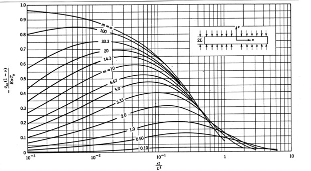
Figure 17. Thermal stresses at the surface of a free plate heated symmetrically by an environment at Ta
through a boundary conductance, h, on faces at z = +/- L.
is controlled by the parameter hL/k, the Biot Number, where k is the thermal conductivity of the material. A large Biot number implies that heat is applied faster than it can be absorbed in the plate; a small Biot number implies that the temperature is quickly transferred through the plate, giving small temperature gradients and low thermal stress.
The motivation for doing new thermal stress tests of very thin sapphire is that the thinness of the material should make its response to heating very different from that of the standard thickness of sapphire microwave windows. As the sapphire becomes thinner and thinner the time needed for a given temperature to propagate into the sapphire becomes less and less. Since the temperature propagates rapidly to the face opposite the heat input, large temperature gradients through the thickness do not exist for sufficiently thin windows. For typical windows, if there is a heat input to one face, this face heats and expands. The opposite, cooler face expands less and is in tension, compressing the hot face. The cold, relatively weak surface of the sapphire is thus where fracture occurs. For very thin sapphire windows this thermal stress buildup does not occur.
For initial experiments a 2 mm thick, irregularly shaped piece of sapphire was quenched in room temperature water and fracture resulted as the temperature was raised to temperatures similar to that reported above. A 0.5 mm thick piece of sapphire also fractured when quenched from 200°C, but the fracture propagated from the edge of the small piece, rather than throughout the area, as did the thicker sapphire. This implied that the damaging thermal gradient was over the width, not the thickness. Next, a soldering iron was used to create a hot spot in the sapphire. First, a standard pencil soldering iron was used to create spot heating to 200°C (measured), without fracturing this thickness of sapphire. Next, a high power soldering gun was used to raise the spot temperature to 500°C, still without fracturing the sapphire. This confirmed that the water quench was a much more severe test than simple spot heating. Spot cooling was performed by placing a drop of water on a heated piece of sapphire. A drop of water falling on the center of a 200°C piece of either the thick or thin sapphire did not fracture either piece. At 300°C a wet Q-tip did fracture the thicker piece, but not the thinner piece. The thinner piece could not be fractured at any temperature, because at higher temperatures the boiling water forms a vapor barrier to heat transfer at the surface that prevents large amounts of heat transfer.
Applying a heat source to a very thin piece of sapphire thus results in a uniform hot spot at one area in the sapphire plate surrounded by a dropping temperature around this area. The spot has expanded and is compressed by the cooler material around it. However, the tensile stress in the outer sapphire is distributed throughout the bulk of the material, and is spread around a much larger area than the spot being heated. Thus thermal stresses are much lower for a very thin sapphire window.
It is concluded that the thin windows developed in this program will be significantly more tolerant of high power microwaves than current power scaling predictions based on decreasing the thickness of the window.
The windows developed in this program can thus be considered to be true thermal membranes, in the sense that the windows are so thin that the temperature through the thickness of the window is constant. Thermal stress in these windows will be a result of expansion in the plane of the window. This will cause the disk to flex rather than create tension in the plane of the disk. Furthermore, the tensile stress will be distributed throughout the thickness of the disk and will be distributed around the periphery of the hot section. Both of these effects will reduce the levels of maximum stress. As a result, the disks should withstand much more heating than is currently possible. None of this would apply for arc heating, which is very localized and would result in large local thermal stresses. However, the resulting stresses in this case as well will be much reduced compared with thick disks.
Total Stress Design. The combination of thermal and mechanical stress determines the overall stress levels in the sapphire. In the case of a membrane the center of the window is in tension as a result of pressure stress, and in compression as a result of thermal stress. The window must be designed with a safety factor at its worst case point of operation, which in this case is where the window is cold. As the window heats up the compressive stress formed at the center will remove some of the pressure tension and increase the window safety factor during operation.
Vacuum Design. Sapphire is an excellent material for vacuum applications. It has no internal volatiles because strength requirements require a perfect single crystal. Surface adsorption is negligible as a result of the near perfect polish required for strengthening. High temperature active metal brazing is used in fabrication to permit high temperature bakeout, and these brazes have excellent vacuum properties. Weld attachment of the brazed window completes the high quality vacuum design of the fixture.
Material Design Strength. The factors that are involved in specifying single crystal sapphire are discussed in the background section. An important factor in microwave window design is the need for large pieces of sapphire. High power microwave systems require larger diameter waveguides and windows. Current 1 MW 110 GHz systems use 75 - 100 mm diameter windows. A best-quality piece of sapphire of this size is expensive in small quantities. With a careful window design, however, it is only necessary to have defect free sapphire in the regions of maximum stress - at the center of the disk; the outer part of the disk can possess some defects. Since sapphire is grown in boules that tend to be defect free at the center but with increasing numbers of defects at increasing radius, it may be acceptable and much cheaper to obtain material that has some defects around the outside diameter.
As a result of the axial symmetry of the microwave power deposition, sapphire is almost always used with its c-axis coincident with the window axis. If another orientation is used the asymmetry in the thermal properties of the window caused by similar asymmetries in the crystal will cause asymmetry in the thermal stress, unpredictable stresses and probably failure in marginal applications. This may not be the case for the thin windows of this program, since the thermal gradients are small.
To date sapphire has been the material of choice for microwave window applications because it has a high strength and a low loss tangent. As both microwave power and frequency (window absorption increases with frequency at room temperature) have increased, standard sapphire windows have reached their limits and are currently a major constraint on the development of high power microwave systems. For this reason other materials (or combinations of materials) have been developed.
At this time the leading window material is chemical vapor deposited (CVD) diamond. Silicon nitride has also been considered, since it has a loss tangent comparable with sapphire and is considered as a result of better thermal properties and perhaps higher strength. Diamond is normally much stronger than sapphire, and its very high thermal conductivity makes edge cooling practical (Table 3). Its low permittivity results in very low reflection.
Table 3. Thermal and loss tangent properties of microwave window material candidates.
Material................Thermal Conductivity(W/mK)....................Loss Tangent
........................................300K..........77K..............................300K..............77K
Silicon (AU-doped)........200...........2000........................20 x 10-6.......10 x 10-6
Sapphire............................60...........1000........................200 x 10-6.......5 x 10-6
Diamond(CVD).............2000...........6000.........................50 x 10-6.......50 x 10-6 (150K)
The strength and thermal conductivity of CVD diamond has made it the leading candidate to replace sapphire in microwave window applications. The ability to edge cool the windows is a major advantage of diamond, avoiding complex flow passages in the microwave channel and only requiring one window. For many applications, however, double windows will be required for safety reasons, where redundancy is required. The primary problems with diamond windows are price and quality. Although the best quality CVD diamond is true diamond the CVD process does tend to create "diamond-like carbon (DLC)" and graphite at the grain boundaries. If the CVD process is not fully optimized this non-diamond material can significantly increase the loss tangent and create a real quality control issue.
Very thin sapphire windows will have losses comparable with diamond at significantly lower cost. Another major advantage that sapphire has over CVD diamond is its resistance to radiation - diamond is an excellent radiation detector. Strengthened sapphire is as strong as CVD polycrystalline diamond (about 1.2 GPa tensile strength). CVD diamond cannot be polish strengthened because its strength is controlled by the weakness of its grain boundaries rather than flaws in its surface. Sapphire also has the potential for much lower microwave losses as a result of its large reduction in loss tangent at cryogenic temperatures, where it also becomes somewhat stronger. If polishing costs can be kept down, the biggest advantage sapphire windows will have over diamond will be cost.
Window Fixture Development and Testing.
This work consisted of the design, fabrication, and testing of the window fixture and its components. The goal of the task was to develop a prototype megawatt microwave window fixture and to test it under realistic conditions, except for the high power testing of Task 4. The primary technique used to increase the microwave transmission power capability compared with standard windows was to make a fixture with sapphire windows that are much thinner than those used in current practice, but supporting the same pressure loads. The thinner windows absorb a much lower fraction of the microwave power passing through them and thus permit much higher transmission before failure.
The windows were made thinner first by strengthening the sapphire, as discussed in Task 1, but also by reducing the maximum stress in the window for the same pressure and thus allowing a window with a fixed strength to survive a higher pressure. The two physical effects that were used to reduce the maximum tensile strength in the disk (the compressive strength of sapphire at room temperature is much higher) were cantilevering at the edge and membrane stress distribution as discussed and explored in Task 1. This task created fabrication techniques that were appropriate to a high vacuum, bakeable fixture to achieve and that would also lead to the desired stress reduction in the window.
Fixture Geometry Design. The basic design was to make a high temperature seal at or near the outer window diameter, and to provide a loading pivot at some lesser diameter. Possible additional constraints were 1) providing the capability to preload the outer diameter by adjusting its initial vertical deflection, and 2) providing the capability to fix the outer edge radially. Constraints that arise from non-mechanical issues include the fact that the fixture design must be compatible with double-disk cooling, that it be compatible with total transmission of microwave power, that it not cost too much, and that it be practical to fabricate. The final prototype geometry and design is discussed in Task 5, but the window brazing technique developed in this task allowed a redesigned assembly that simplified even the standard double window fixture and formed an elegant final prototype window fixture design.
Fixture Fabrication To fabricate a prototype window fixture, 76 mm diameter, 0.043 mm thick sapphire disks were used, together with old window fixtures available at ORNL from Dr. Bigelow's laboratory. These fixtures were built to form a double disk window for standard 63.5 mm inside diameter waveguide. They originally had alumina disks brazed on, but these disks had been cracked during earlier use.
Two brazing designs were defined and tested: the first was edge brazing of a window in a tube, and the second was flat brazing to a ring. The flat braze simulates a braze to a cup, similar to the standard window fixture. The purpose of these tests was to determine if the sapphire windows would survive the metalization and brazing process, and to determine the stress and deflection in the windows resulting from the brazing.
Preliminary analysis of the stresses in the brazed piece indicate that the moment, stress, and deflection generated in the sapphire disk is limited by the strength of the metal it is brazed to. Calculation of the stresses indicates that they can be very large, such that only very soft materials that yield at low stresses can be used in the joint to prevent breaking the sapphire. Normally the temperature of the braze would be an important factor in that it controls the total thermal expansion mismatch that must be accommodated in the joint. However, the thermal stresses that are caused are so great that the yield strength of the metal (or the break strength of the sapphire) is reached at even lower temperatures than that used for soldering. This would imply that the higher temperatures associated with brazing can be tolerated; this conclusion was tested in brazing experiments.
For these experiments three 76 mm diameter wafers were purchased. These wafers are the cheapest thin sapphire material available for testing, but they have the disadvantage of being R-plane disks and having the orientation flat cut out of the edge. The extensive (and proprietary) brazing work was performed by 3E Laboratories to develop the sapphire window fixture fabrications techniques. The brazing was done at high temperature (900°C) to demonstrate a joint that could be baked out at temperatures as high as 600°C.
Brazing into the end of a tube had the advantage that the external metal would be able to keep the braze joint and sapphire in compression as the part cooled from brazing temperature. The tube thickness, tube strength, and type of metal were chosen so that the metal would yield in response to the tensile stresses on it and limit the maximum stress in the joint. This braze joint was unsuccessful, breaking the window, but the failure was not one of the technique. The UC wafer windows all have an alignment flat on the edge for electronics processing; the window broke where the flat diverged from the tube wall. The differential stress at the corner of the gap between the wafer flat and the tube caused the break. Rather than try to match the tube end shape to the wafer shape or pay much more to get a round window, the face braze test was attempted next.
The face braze consisted of using a 89 mm OD and 63.5 mm ID very thin metal ring brazed to the outside of the 76 mm OD sapphire window. The metal ring was annealed to be as soft as possible to minimize thermal stresses during the brazing process. The initial braze attempt was successful, but left a gap between the window and the ring at a local azimuthal position as a result of bowing of the metal ring. Although past practice had shown that rebrazing causes failure of the window, a rebraze under a heavier weight was attempted because the part was useless as it was. The rebraze was successful without difficulty, illustrating the robustness of the design and demonstrating the feasibility of the process. A second assembly was then brazed in a similar manner for inclusion in the final window prototype.
Fixture Testing. Fixture testing consisted of vacuum, heating, pressure, and microwave testing.
Pressure Testing. Initial pressure testing of thin sapphire windows in a fixture was conducted on both halves of the standard fixture that had been fabricated with thin windows in Phase I. The sapphire windows were 76 mm diameter, 0.325 mm thick that were matt finished on one side and epi-polished on the other. The matt side of the finish was placed on the pressure side where the stress was lowest, since the matt side was the weakest. The windows were metalized (again on the epi side) and then soldered to the copper cup of a standard fixture, replacing the normally thicker window.
Pressure testing was done by evacuating the waveguide side. This fixture was originally intended to be used to test the windows for microwave response in the resonant ring, but when it was first pumped down for leak checking at ORNL one of the windows immediately broke. The fixture was then sent to Thoughtventions for inspection and further testing of the remaining soldered window.
A number of odd features were noted. First, the window broke without cracking the outer 5 mm wide periphery that had been soldered to the copper. Second, the solder joint of the broken window that was visible through the window looked substantially different in both color and texture compared with the unbroken window (that had also been evacuated).
At Thoughtventions, the unbroken window was evacuated to full vacuum more than 5 times without breaking to determine if it would fail as a result of multiple loading cycles and the associated flexing. The window was next tested for deflection under load to see if the window was behaving as predicted by modeling.
Initial setup for the deflection tests showed that the window was bowed toward the matt and pressure side. Examination of the soldering process then showed that the bowing was a necessary part of the soldering process. For soldering, the window and copper cup were first heated until the solder melted. When the solder solidified, the window and copper were fixed relative to each other at the interface, and subsequent cooling to room temperature contracted both materials by an amount determined by their coefficients of thermal expansion. In the case of sapphire and copper, the copper contracted much more than the sapphire, leaving the copper under tension, the sapphire under compression, and the window bowed. The center deflection of the window was found to be 0.15 mm from the neutral plane in the unloaded case, and 0.21 mm in the loaded case for a total displacement of 0.36 mm, or 1.1 times the disk thickness.
The soldering thus places an effective preload on the disk in a similar manner to the cantilevering caused by an O-ring seal outside the pivot radius. Note that this effect is only noticeable for the very thin windows tested in this program. It would be ideal if this preloading could be substituted for the cantilevering, since this would greatly simplify the fixture design. In the case of the soldered windows this configuration unfortunately puts large stresses on the pressure side of the disk at the edge of the aperture. Presumably this caused the failure of the disk. After a series of deflection tests, the second window broke in a similar manner to the first. It was later found during Task 1 analysis that the mounting configuration put the matt side in considerable stress during pressure testing and caused the window to break - the strengthened windows would not be close to failure.
The final prototype windows were pressure tested a number of times. They were first vacuum checked for leaks at 3E Labs as part of the braze inspection procedure. The windows were then sent to Thoughtventions where one window was pressure tested to 3 atm, and its deflection during pressure testing measured. The windows were then sent to ORNL where they were further vacuum tested after welding into the fixture. One window cracked circumferentially within the braze zone, but this did not affect the window seal or microwave capability.
Heat Testing. Heating tests were confined to the thermal stress testing described in Task 1. These tests demonstrated that the very thin windows will not be susceptible to hot spots as normal windows are. Inadvertent heat testing was done during e-beam welding at ORNL, when the e-beam heated the fixture locally. The windows were unaffected except that the circumferential crack elongated without affecting the window capabilities. The only testing needed beyond this is high power microwave testing.
Bakeout Testing It is not clear how many cycles of operation would be required during actual use or how many baking cycles would be required to demonstrate a successful design. Standard bakeout temperatures are 200 and 400°C, but CPI requires 500 or 600°C bakeout. It is believed that this high a bakeout temperature was demonstrated by the fabrication procedures themselves. A standard fixture was used, together with welding and a 900°C sapphire braze. These techniques should be adequate for a 600°C bakeout.
Cooling Tests. The cooling flow was tested in a standard double window fixture during microwave testing at ORNL. No unusual phenomena were observed.
Microwave Testing. The window fixture was first tested under low power microwaves; it responded as a very thin piece of sapphire. There are minor questions about system response once the disks have undergone the few mm deflection that is expected under full pressure coolant load. It is believed that this effect to be minor, and one that can easily be compensated for.
Resonant Ring Development and High Power Testing.
This work was performed at ORNL under the direction of Dr. Timothy Bigelow. The objective of this task was to develop a quasi-optical high power HE11 resonant ring to provide a means for high power window testing of microwave components at 1.5 MW of transmitted power or greater. Such a resonant ring would be an economical test device to perform high power microwave window tests using existing lower-power (200 kW) gyrotron sources. These low power gyrotrons use conventional windows operating at the limit of their performance capability. The resonant ring will permit off-line testing of new window concepts independently of gyrotron development, a capability that will greatly simplify the process of window and component development by making it an off-line parallel effort.
The resonant ring produces extremely high microwave power levels in a waveguide by forming a traveling wave resonant cavity that captures the power from a microwave source into a closed waveguide loop or ring. The power in the ring rapidly builds up to a level that is limited only by losses in the waveguide structure and window or other device under test. A traveling wave resonance is significant in that the electromagnetic field structure in the waveguide is identical to that of a much higher power source being transmitted in a waveguide to a matched load. A conventional resonant cavity has a standing wave pattern where the field structure varies rapidly along the length of the cavity, which would produce unrealistic heating patterns in a window under test.
The idea for a quasi-optical resonant ring [19] was derived from earlier work with a conventional single-mode rectangular waveguide resonant ring [20] that has been occasionally used for testing windows and waveguide breakdown in various microwave components. The resonant ring consists of a loop or ring of waveguide and a directional coupler to couple power into the ring. The length of the ring is adjusted to equal an integral number of waveguide wavelengths at the frequency of interest. The directional coupler also couples power out of the ring. However, at resonance, the power coupled out of the ring equals the uncoupled input power but is out of phase, so that any uncoupled power from the source is canceled out and all the power goes into the ring. For maximum gain, the coupler value must be set to be compatible with the losses in the ring. With low losses, for instance <1%, the ring gain or ratio of power in the ring to power at the input port is greater than 10.
The quasi-optical resonant ring has a similar mode of operation to that of a conventional resonant ring, but some innovations were required to implement the concept for high power millimeter waves. High power microwave or millimeter wave windows and waveguide systems must be built using highly oversized waveguide to reduce resistive wall losses and to reduce electric field levels so that arcing can be avoided. An oversized waveguide is one that is large enough in cross section to allow more than a single dominant mode to propagate; for practical systems operating at >50 GHz and >200kW cw, hundreds of modes can propagate. A waveguide must remain less than a wavelength in width or diameter to allow only a single mode to exist, which makes high frequency single mode waveguides extremely small and lossy. A highly oversized waveguide can have very low resistive loss and low electric fields but it can also suffer from mode conversion loss if it is not quite straight. Power lost to other modes is not easily recoverable and these modes are likely to have higher loss and will be quickly damped. Making bends in oversized waveguide is difficult because of the mode conversion losses they introduce. A miter bend can be used for a waveguide that is highly oversized with increasingly lower loss as the diameter to wavelength ratio increases, and this fact is taken advantage of in this resonant ring design.
Two types of oversized circular waveguide are commonly used for high power transmission of millimeter waves. In each type, a low order mode has the lowest loss, the most convenient properties, and is the mode of interest. A smooth wall circular pipe will propagate the TE11 mode with very low loss. This mode has a circular electric field pattern and very low wall currents and therefore has low resistive loss. It also has reasonably low mode conversion loss in miter bends. Unfortunately, the circular electric field pattern forms a rather poor conical, unpolarized radiation pattern when the waveguide is terminated into free space, so it requires a mode conversion device if a narrow, polarized pencil beam is desired. If a circular waveguide is corrugated on the inside wall with electrically small grooves in the azimuthal direction, a hybrid HE11 mode propagates that has nearly perfect linear polarization and a gaussian-like field distribution which forms a low-sidelobe gaussian-like pencil beam when the waveguide is terminated in free space. This mode has comparably low loss as with the TE01 mode. Resonant ring designs for both the TE01 and HE11 modes are of interest, but the HE11 mode device is more complicated to build. For this reason the TE01 mode was used in Phase I to demonstrate feasibility whereas the HE11 mode was used for high power work in Phase 2.
To form a ring, the quasi-optical resonant ring requires 4 bends of 90° and a directional coupler. The configuration shown in Fig. 18 was adopted as the most useful, although others are possible. The directional coupler consists of a perforated plate for the TE01 mode device or a closely spaced wire grid for the HE11 mode.
Figure 18. Schematic of the resonant ring.
The input port is connected to the high power gyrotron source and the output port is connected to a dummy load to absorb any power not coupled into the ring. To tune the ring, the overall length is adjusted with short bellows in two sides or by moving the plate in one of the miter bends slightly outward.
The effective power gain or ratio of electric field in the ring to the input field level can be shown to be
Ering/Einput = 1/[(C)0.5 - α (C-1)0.5] = (Pring/Pinput)0.5 (17)
where C is the directional coupling power ratio and α is the waveguide loss for a single pass including mode conversion loss, resistive loss and any loss in a component or window under test. For a given total loss level in the ring, a particular value of C gives the maximum possible ring gain. If α is small, Copt becomes large and the ring gain increases rapidly. Since the oversized waveguides used in this work have very low losses, the ring loss will be dominated by miter bend mode conversion loss and the window loss. If the mode conversion loss is too large, the mode that power is converted into can also build up in the ring and will cause a small level of interference with the primary mode at certain frequencies where both modes are resonant. Fortunately, for increasing frequency and waveguide diameter, the miter bend loss decreases significantly as indicated in the Table 5. The predicted optimum performance for a quasi-optical resonant ring with TE01 and HE11 modes in two waveguide diameters is shown in Table 5. These estimates include a 1% window loss.
The resonant ring was constructed and first tested at low power in the ORNL Fusion Energy Division microwave development laboratory. This laboratory is well equipped with a wide variety of test equipment and oversized waveguide components available for past fusion heating experiments, making development much easier and faster. The test resonant ring was fabricated using 63.5 mm (2.5") smooth-wall copper waveguide and existing miter bends used for the TE01 mode. A directional coupler was formed using a cross miter bend with a perforated plate inserted between. The coupling value was controlled by the plate thickness, perforation hole size and hole density. Since round holes were used, the polarization of the TE01 mode was accurately transmitted through the perforated plate. Two bellows sections were used to demonstrate frequency tunability. Power was fed into the input port using a TE01 mode transducer from standard rectangular waveguide (WR-15 for the 50-75 GHz band) and a gradual diameter taper to large diameter for high mode purity. A TE01 mode purity of 99% was generated by this apparatus. For low power testing purposes, a 50-75 GHz sweep oscillator and a scalar network analyzer were used to generate and monitor the test signals.
Table 5. Predicted ring gains with 1% window loss included
| 53.2 Ghz TE01 mode |
53.2 Ghz HE11 mode |
110 Ghz HE11 mode |
170 Ghz HE11 mode |
|
| Miter bend loss 63.5 mm |
4.3% | 2.4% | 0.95% | 0.71% |
| Ring power gain 63.5 mm |
6 | 10 | 20 | 25 |
| Miter bend loss 88.9 mm |
2.63% | 1.35% | 0.65% | 0.43% |
| Ring power gain 88.9 mm |
8.5 | 15 | 25 | 35 |
Actual monitoring of signal levels in the resonant ring was difficult, since a mode-selective sampling coupler is required. For these tests, a perforated screen was used for one of the miter bend reflectors that radiated a small portion of the TE01 pattern (slightly distorted by the bend) outside the waveguide where a small sampling horn was placed at a peak in the radiation pattern. This arrangement gave a reasonably accurate and directional sample of the TE01 wave inside the ring with good mode selectivity. The signal level and corresponding ring gain can be calibrated relative to an open end waveguide when the pickup horn is placed at the same distance away from one of the miter bends with the reflector plate removed to spoil the ring resonance.
The specific directional coupler perforated plates that were used gave an optimum gain in the 50-54 GHz range. In this range, the C value was determined to be 5-10 dB and the ring loss (based on theoretical predictions for miter bend mode conversion loss) totaled ~17%. The theoretical ring power gain was 6 and the measured ring gain was 6-8 which was excellent agreement. With a suitably sized hole array, the ring gain can be optimized for any frequency range of interest.
The physical path length of the test ring configuration was measured to be 1.94 m, which gave a resonant frequency spacing of ~160 MHz. Measured plots of ring gain vs. frequency were nearly identical with the exception of the null region between peaks filled in at 10-15 dB below the peaks due to the non-resonant mode converted power.
Comparisons between the model and experiment for the proof-of-principle resonant ring test were very favorable and indicated that the concept performs properly and provides effective power gain as desired. Predictions by the model imply that at higher frequency or larger waveguide diameter, the ring performs even better. Next, a high power HE11 mode version of the ring was constructed for testing high power at 53 GHz using an installed and operational cw gyrotron system at ORNL.
A HE11 mode launcher was modified for lab tests of the HE11 resonant ring, low power tests of the HE11 resonant ring were performed. The resonant ring worked well at low power and measurements agree with theory. Tuning of the ring was practical and simple. These tests demonstrated a greater than factor of 10 power gain. At low power a ring gain of over 20 was demonstrated near 53 GHz using a perforated plate coupler. Frequency tunability by shifting one miter bend plate was also demonstrated using perforated plates for the directional couplers. These were adequate for medium pulse length tests; for longer pulse tests water cooled grids were added to the directional couplers.
Second order effects were investigated. These included reflections from a window, a miter bend, the dummy load, or another component under test that could have de-tuned ring gain. It is also possible that the double miter bend mode re-conversion can enhance performance. A lack of mode purity of the input power was also investigated.
The 53 GHz gyrotron system at ORNL provided the 200kW a high mode purity HE11 mode to drive the resonant ring unit as shown in Fig 19. An oversized waveguide configuration was designed for the high power resonant ring tests, and a series of mode converters and mounting fixtures were fabricated.
Figure 19. The waveguide configuration for high power window tests using the resonant ring.
A TE01-TM11 mode converter for high power tests was fabricated, and its mode purity was found to be >98%. The remaining two components were the TM11 to HE11 mode converter and the HE11 corrugated diameter uptaper. The TM11-HE11 high power transition was modeled, and these two components were designed and fabricated.
To convert from the TM11 smooth-wall waveguide to the HE11 corrugated waveguide, a gradual corrugation depth taper was required. The taper length was carefully controlled to produce the exact amount of mode conversion to generate a high purity HE11 mode. The HE11 mode can be decomposed into smooth wall modes in the following ratios: TE11 82%, TM11 14%, TE12 0.6%, TM12 2%, and small amounts of higher modes. The TM11-HE11 mode converter was designed with a waveguide diameter step cascade code developed previously to analyze circular waveguide structures consisting of a series of smooth wall waveguide sections. A large number of higher order, non-propagating modes were included to properly model the small diameter changes at each corrugation. The resulting mode converter design had ~155 corrugations of linearly varying depth and a short phase correcting section at the output. Mode purity was estimated to be >98%. The converter had an input and output diameter of 38.3 mm and a length of 305 mm.
The diameter uptaper from 38.3 mm to 63.5 mm was then fabricated to match the diameter of the resonant ring and windows to be tested. A square root profile was designed which provides the greatest mode purity for the shortest length. This section was drawn and fabricated. CW cooling capability was added for the high power tests.
Other gyrotron facility setup tasks completed include the fabrication of a frame to support the TE01-TM11 and TM11 to HE11 converters and a second frame to support the resonant ring and test window. High vacuum was established in the waveguide and the resonant frequency of the ring was tuned to match gyrotron frequency. The ring resonant frequency must also be controlled to overcome thermal drift, and optical arc detectors must be installed. A cooled miter bend coupler has been shown to be practical for cw operation; this coupler was also fabricated.
The goal of creating a resonant ring apparatus that can test microwave components at high power using available lower power drivers was also achieved. The resonant ring concept feasibility was demonstrated through both modeling and experiments, indicating that large power gains are practical and can be used for high power component testing with currently available microwave sources. Furthermore, the ring is expected to perform even better at the higher frequencies of future microwave systems. High power operation of the ring was close at this writing, delayed by competing programs at ORNL.
Window fixture tasks. Work was done to modify the existing double disk window fixture is nearing completion. The two waveguide sections have been corrugated and machined to accept a short section that has a weld lip to be welded to the sapphire disk braze assemblies. The weld sections will be brazed into the waveguide halves when a final gap dimension can be determined. The window reflection vs. Double-disk gap has been modeled using a wave impedance code. Due to the window deflection that occurs with vacuum loading and from FC75 coolant pressure, it is expected that final tuning of the match frequency will be required by adjusting the gap with shims. A nominal gap of either 2 or 4 mm is a low reflection spacing. The 4 mm central gap will be chosen so that the edge gap with the deflection of two disks subtracted will be greater that ~ 2mm to allow for sufficient FC-75 flow.
Microwave Window Prototype Fabrication and Testing.
Using all of the information and developments of the previous four Tasks a final prototype window fixture design was developed, and a final prototype fabricated. This fixture has a clear aperture diameter of 63.5 mm to be consistent with the microwave ring apparatus at ORNL that was used for microwave testing. Quite a few microwave window fixture designs were considered and are discussed in Task 2. Strengthened sapphire was used as the microwave window material. The thickness of the window was determined by the available thicknesses made by Union Carbide. The window is a factor of 3 thinner than standard windows of this diameter and thus suitable as megawatt power level window, since current windows are used up to 500 kW.
The strengthened sapphire windows were built into a standard fixture that was modified for the new windows. The sapphire windows were first face-brazed onto flat stainless steel rings. Similar stainless steel rings were welded into the stainless steel fixture. The two stainless steel rings were then e-beam edge welded together to complete the fixture. This is a simpler and more robust manufacturing technique than being used currently. In standard double window microwave fixtures, the windows are brazed onto a copper cup with a relatively low temperature braze after the copper cup has been high temperature brazed into the stainless steel fixture. The soft copper allows the braze joint to be formed with low stresses. The copper cup is structurally weak, however, so that the window assembly must be supported against pressure loads by a backing ring. The present design needs no backing ring, since the window rests against the bulk waveguide. The standard fixture also has a relatively low bakeout temperature because of the double braze technique.
A schematic of the final Phase 2 fixture design is shown in Fig. 20. Modeling allowed reassessment of the cantilevering approach and suitable adjustment of the design for both simplicity and the greatest stress reduction. This design also incorporates the program advances made in window brazing. In other respects the fixture design is unchanged; face cooling and mounting to the microwave duct.
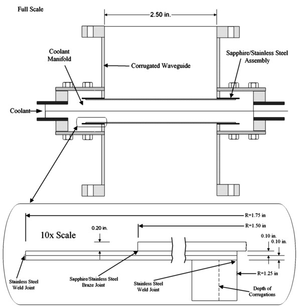
Figure 20. Prototype high power window fixture design.
Although the Phase 2 prototype window uses Union Carbide sapphire and a 63.5 mm aperture, a larger optimized prototype window has been designed, using identical fabrication techniques. The large deflection modeling of Task 1 was used to design a nominal sapphire window for a 102 mm diameter (multi) megawatt waveguide. The specifications for this window are:
Double window
FC-75 cooled at 1 atm pressure (design based on 100% pressure safety factor)
100 mm diameter aperture
0.1 mm thick
600°C Bakeout
These specifications represent significant advances both in the thinness of the window and the temperature of the bakeout. The thickness of the windows is specified using large deflection modeling, taking advantage of the physical effects of both the higher design strength of the sapphire from strengthening and the lowering of peak stress in the window through membrane effects during deflection of the very thin window. Membrane forces allow stress to be distributed throughout the thickness of the window, rather than concentrating them at the surface away from the pressure as in flexing disks. The membrane regime becomes more important as the disk becomes thinner; the disk thickness has been reduced both by reducing the pressure loading from the standard 4 atm, and by increasing the failure stress through polish strengthening. The higher bakeout temperature has been achieved by developing a higher temperature brazing process.
Although advances in polishing have been made in the program, the 100 micron thickness windows that are optimal can not be made at this time, and will be part of a Phase III effort if commercialization is possible.
When the windows become extremely thin their larger deflection changes the interaction with the microwaves passing through them. For a 1 atm pressure load a 65 µ m thick window with a 31.8 mm radius will have a central deflection of 1 mm, whereas for the a 0.43 mm thick disk of the same radius, the central displacement is approximately 0.5 mm. For a double window fixture with pressurized coolant between the windows and vacuum outside the windows, both windows will bow outward, so that the spacing between the windows will increase by a maximum of twice the central deflection. The increase in total spacing will depend on the width of the cooling channel.
Testing of the final window fixture took place in stages as the fixture was assembled. The testing consisted of:
1) Pressure testing.
2) Heat testing.
3) Leak testing/bakeout.
4) Low power microwave testing (ORNL)
5) High power testing (ORNL).
Pressure testing consisted first of vacuum leak checking of the brazed windows at 3E Labs where they were brazed, followed by deflection testing under pressure at Thoughtventions. The windows were vacuum tested again at ORNL after they were welded into the fixture, and pressure tested (FC-75) during cooled operation at high power.
Heating and heat flux testing was performed on an isolated sapphire window and is described in Task 1. The windows are so thin that temperature gradients cannot be created across the thickness of the window, and thermal stresses resulting from face cooling are eliminated. An extremely high bakeout temperature was demonstrated by rebrazing a window at 900°C without harming the window or the window seal. Furthermore, by brazing the window into a ring, brazing stresses could be separated from the rest of the fixture fabrication process.
Low power microwave testing was performed at ORNL without problems, as expected from a clear-aperture sapphire window.
The window will be tested in the quasi-optical high power resonant ring system at ORNL to progressively greater power levels up to at least 1.5 MW. Fixture behavior will be monitored with an IR camera and by examining the microwave characteristics of the ring, which by its operation will be able to detect losses in its components. Unfortunately commercial concentration on diamond windows has caused the effort in this program to focus on the resonant ring itself as the program development with the greatest potential impact on future microwave component progress.
CONCLUSIONS AND FEASIBILITY ASSESSMENT
The goal of this program was to demonstrate the feasibility of making ultrathin sapphire microwave windows. The goal of making ultrathin windows has been shown to be conclusively achieved through pressure failure experiments where sapphire windows a factor of 3-5 thinner than current practice have been shown to support the same pressure that must be supported by current windows. There is no question that these windows will support Megawatt microwave power levels, since microwave absorption is known to be a linear function of material thickness, and power absorption is the current limit on microwave windows. The remaining question of whether the thinner sapphire windows could be assembled into a fixture was answered positively by successfully fabricating a standard double window fixture using the ultrathin windows. Commercialization has been frustrated by the development of competing diamond window technology.
A number of contributing results and developments have also been achieved during the Phase II effort. The contributing results include:
- Development of polish strengthening techniques.
- Development of modeling that allows accurate prediction of peak stress of a circular window under pressure loading.
- Failure testing to demonstrate sapphire strengthening and validate modeling.
- Development of a simplified double-window fixture design.
- Development of thin-window brazing techniques.
- Pressure testing of the fixture.
- Temperature testing of the fixture.
- Low power microwave testing.
- High power microwave testing.
The final window fixture used 0.43 mm thick sapphire in a microwave fixture that had an aperture of 63.5 mm. The fixture was pressure tested to 1 atm and will be tested under high power microwaves to power levels of greater than 1 MW if possible.
A number of ancillary important developments have also taken place. A resonant ring microwave power amplifier was demonstrated and the facility was used to test strengthened sapphire window fixtures for system function and microwave response. The novel quasi-optical resonant ring device was both modeled and tested, providing large power gains. It will allow testing of the windows developed in this program at power levels of over 1 MW using existing 200 kW gyrotron power sources at ORNL. This was the only way that the new microwave windows could have been tested, since few megawatt microwave facilities are available at this time. Microwave power tube companies have their own in-house development efforts (in this case using diamond windows) and are not willing to test unknown systems. DOE fusion facilities are under such heavy use that they cannot spare the time and effort required to test new systems.
It has been found that the new thin sapphire windows are immune to the standard failure mode of microwave windows - thermal stress fracture. The most common cause for microwave window failure is the development of a hot spot on the window, which boils the coolant and further reduces cooling, increasing local thermal stress until the window fails. The thin windows are thin enough so that they have no significant thermal gradients through their thickness and are thus not subject to large thermal stresses as a result of hot spots that may occur.
Additional novel microwave window concepts have been developed through a low-level, secondary effort. A tube-grid cooled single sapphire window was built and tested. It was shown to be transparent to microwaves of the proper frequency, and to tolerate a 1 kW heat load without effect. This window shows long term promise for use in a variety of high power, single frequency microwave systems. Another promising concept is the use of He gas cooling to practically and dramatically reduce the microwave absorption in sapphire windows.
Acknowledgements: The financial support of DOE under Grant No. DE-FG02-95ER-86038 is gratefully acknowledged, as well as the support of the project manager, T.V. George, without whose backing this work could not have been performed.
REFERENCES
1. R. Heidinger, "Ceramic materials for microwave windows," Int. J. Electronics, 64, 1, 37 (1988).
2. J. -G. Wegrowe, F. Moons, M. Vassiliadis, and E. Zolte, "Limits of Operation of Conventional RF Windows for Electron Cyclotron Wave Launchers in a Reactor," NET Report EUR-FU/XII-80,
3. G. P. Pells, "Ceramic Materials for Fusion Reactor Applications," J. Nucl. Matl., 122/123, 1338 (1984).
4. L. M. Belyaev (Editor), "Ruby and Sapphire," Nauka Publishers, Moscow, Available From National Technical Info. Service, Springfield, VA 22161, (1974).
5. H. P. Kirchner, and J. M. Ragosta, "Crack Growth from Small Flaws in Larger Grains in Alumina," J. Am. Ceramic Soc., 63, 9-10, 490 (1980).
6. E. Prochnow, and D. F. Edwards, "Preparing Precision Ultrafine Sapphire Surfaces: A Practical Method," Applied Optics, 25, 16, 2639 (1985).
7. J. Askinazi, "Large aperture, broadband sapphire windows for common aperture, target acquisition, tracking and surveillance systems," Proc. SPIE, 3060, 214 (1977).
8. H.P. Kirchner, R.M. Gruver, R.E. Walker, "Strengthening Sapphire by Compressive Surface Layers," J. of Appl. Phys., 40, 9, 3445 (1969).
9. A. V. Gapanov, et.al. "Powerful Millimeter-Wave Gyrotrons," Int. J. Electronics, 54, No. 4, 277 (1981).
10. K. Felch, et.al., "Achievements in the CW Operation of 140 GHz Gyrotrons," XI Int. Conf. on IR and MM Waves Conf. Digest, Pisa, Italy, 43, Oct. (1986),
11. P. F. Becher, and M. K. Feberg, "Mechanical Reliability of Current Alumina and Beryllia Ceramics Used in Microwave Windows for Gyrotrons," ORNL Report TM 8555, Feb., (1983).
12. A. Ibarra, J. Molla, R. Heidinger, and G. Link, "The temperature function of the anisotropic permittivity of sapphire ," 15th Conf. on Infrared and Millimeter Waves, Orlando, FL , (1990).
13. R.J. Roark, Formulas for Stress and Strain McGraw-Hill, New York, NY, 1954.
14. S. C. Bates, and L. Liou, "High Performance Sapphire Windows ," Technology 2002, NASA Conference, Baltimore, MD, (1992).
15. S. Timoshenko, and S. Woinowsky-Kreiger, Theory of Plates and Shells McGraw-Hill, New York, NY, 1987.
16. Z. Du, et.al., "Int. J. Infrared and MM Waves, 9, 597 (1988).
17. R.W. Tustison (Editor), "Window and Dome Technologies and Materials V," SPIE Proceedings, 3060, (1997).
18. N. A. Marcuvitz, Waveguide Handbook, Vol. 10, MIT Radiation Lab Series.
19. T. S. Bigelow, "A quasi-optical resonant ring for high-power ECH window testing," Conf. Digest IR and MM Waves , (1994).
20. L. J. Milosevic & R. Vautey, "IRE Trans. MTT, 136, April (1958),