AN OPTIMIZED SEMI-FLUSH FLASHER
40 Nutmeg Lane
Glastonbury,CT 06033
PROJECT SUMMARY
Airport runway lights are a critical component of the systems that allow safe aircraft landing procedures under a wide variety of environmental conditions. Central to approach lighting systems are the flasher lights that serve to guide pilot approach. As airports grow and need to use more of their allocated land, it will be more and more necessary that approach flasher lights be inset into the runways. This SBIR project is designed to develop a significantly improved inset flasher light that meets all of the FAA specifications for flashers.
The Phase 1 project described in this report was intended to demonstrate the technical feasibility of a greatly improved inset flasher optical design, and to demonstrate a sound foundation for the development of a Phase 2 prototype inset flasher and Phase 3 commercialization of this prototype.
Detailed work includes the optical design, the electrical and optical fabrication and setup, feasibility experiments and analysis, and prototype preparation. A design was developed that maximizes the light output within an envelope that is 10 vertical degrees from the horizontal and 30 degrees wide from a forward pointing direction. Light was collected from a compact arc flashlamp and focussed through an aperture characteristic of an inset lighting fixture. The relative gains in optical efficiency compared with present systems have been analyzed and assessed. A test flasher fixture was fabricated using the new optical design together with the appropriate electrical driver system for the flashing. A fast optical detector was fabricated and calibrated to accurately measure the photometrics of the system. The flasher system was tested for brightness, geometrical brightness pattern, and intensity time dependence, and its performance was compared with FAA specifications and the overall lighting power efficiency of current systems.
Technical feasibility of the concept has been demonstrated, and Phase 2 and Phase 3 program plans have been developed. plans A variety of the engineering aspects of the proposed prototype inset flasher have been considered, a preliminary design of the Phase 2 prototype has been defined, a plan has been defined for development of the prototype, and a Phase 3 commercialization path described. The Phase 2 prototype uses an optimized Phase 1 optical design and includes the necessary engineering characteristics that will make it a practical, commercial device. Thoughtventions Unlimited LLC will provide most of the technical contributions for Phase 2, joining with Flight Light, Inc. (Sacramento, CA) who will commercialize the new inset flasher system. Flight Light is an established airport lighting manufacturer that has been participating as a partner in the SBIR process since it's inception.
Identification and Significance of the Problem. Airport runway lights are a critical component of the systems that allow safe aircraft landing procedures under a wide variety of environmental conditions. Central to approach lighting systems are the flasher lights that serve to guide pilot approach. As airports grow and must more efficiently use their allocated land, it will be increasingly necessary that approach flasher lights be inset into the runways to so that the extra land used by above-ground flashers can be converted to runway length. The needed inset flashers place severe constraints on the enclosed optical systems in that high intensity light must be moved through a small aperture. Furthermore the inset flasher systems must withstand a variety of manmade and natural harsh environmental constraints. Current inset flasher systems are inefficient and barely meet specifications using high-powered flashlamps. A new, efficient inset flasher system is needed for airport runway lighting systems.
The Innovation. The central feature of an improved optical design is a compact-source arc lamp combined with a parabolic focussing reflector to greatly improve the light transfer efficiency through the small inset flasher aperture. Shrinking the flash light source size by a factor of 10 compared with current designs allows greatly superior focusing and manipulation of the light. Compact arc lamps are a comparatively recent development that have been extensively developed for other applications so that they can be safely applied and used to great advantage for airport lighting systems. The new prototype inset flasher system can also take advantage of the great improvements made in commercial equipment for the various electrical driving systems for flashers. Electrical circuitry is much smaller and cheaper, and entire system functions have been combined into single plug-in boards. Power electronics has made similar progress, becoming much more efficient. Thoughtventions Unlimited LLC provides the technical expertise for the program, while Flight Light, Inc. (Sacramento, CA) provides the industrial experience and commercial partner as an established airport lighting manufacturer.
Phase I Results Summary
Phase 1 research has provided the analysis and experimental data needed to demonstrate the technical and economic feasibility of the new inset flasher design.
The Phase I research results of primary importance are summarized as:
A Phase 1 alpha prototype was developed with the following measured approximate characteristics:
Light Output:
1) Intensity: 0 to approximately 20,000 effective candelas.
2) Angular distribution: within +/- 5° relative to optics can top base plane: +/- 15° in the other dimension.
3) Pulse length 500 µs.
4) Single fire flash.
5) Significantly superior light collection/energy efficiency compared with current designs; estimated to be a factor of 2 better.
6) Highly repeatable flash.
Arclamp:
1) Compact arclamp has lifetime typical of standard flashlamps currently in use.
2) Small light source size - 1.5 mm diameter.
3) Large stable turndown ratio - lamp is stable at reduced power and intensity.
4) Moderate cost, commercial lamp.
Optics:
1) Standard components/ not high cost.
Electrical:
1) Flash energy measured and variable from 0-80 Joules.
1) 120 VAC single phase, 3 wire
2) Low power.
3) Low voltage systems except near lamp.
4) Simple, but subtle design.
Physical:
4) Reflector 12.5 cm diameter.
5) Output beam passes through standard inset flasher casting.
6) Low weight.
7) Rugged components, except flashlamp, which has robustness typical of flashlamps currently in use.
8) No output prism.
The Phase 1 program addressed a variety of issues with respect to the technical and economic feasibility of the project. The achievements of the Phase 1 program are summarized as follows:
Background
Airport Lighting Systems. The specific system components addressed in this proposal are those related to semi-flush flasher lights. These lights are part of both the Medium intensity Approach Lighting System with Runway alignment (MALSR) and the High Intensity Approach Lighting System with Sequenced Flashing Lights, Category II (ALSF-2). The white flasher lights are distributed along a runway axis and lead into the steady-burning runway threshold lighting pattern with sequential flashes. The number of flasher lights is determined by the runway length.
FAA Specifications. Specifications for the semi-flush flasher discussed in this proposal are described in document FAA-E-2689a [1]. The bulk of this document specifies the operation, electrical systems, materials, testing, and safety features associated with the flasher. This proposal is concerned technical features of a semi-flush flasher, which is specified as follows:
Light Output:
1) Intensity (EFFECTIVE candelas) in 3 steps: High: 5,000-20,000; Medium: 500-2,000, Low: 150-600
2) Angular distribution: light axis 7.5° above horizontal, intensity maintained in envelope +/- 5° and +/- 15° horizontal relative to this axis.
3) Pulse length greater than 250 µ s and less than 5,500 µ s.
4) Flash frequency 2 times per second.
Lifetime:
1) After 250 hrs continuous, pulsing 2 times per second intensity greater than 70% initial intensity.
2) Less than 1% missed flashes.
3) Flash tube: greater than 1,000 hours life on high intensity mode.
Electrical:
1) 120 VAC single phase, 3 wire
2) Less than 550 W
3) Less than 53 A rms, 75 A peak.
4) Trigger components greater than 50,000,000 cycles lifetime.
Physical:
1) Stainless steel, aluminum or equivalent non-ferrous metal
2) Axis adjustable over 25° vertical.
3) Convenient replacement of components but built to withstand shock and vibration.
4) Reflector less than 18 cm diameter.
5) < 66 cm wide, < 2,580 cm2 area above pavement, < 2.6 cm above surface, outer edges flush.
6) Maximum weight 5 lbs.
7) Watertight.
8) Maximum temperature remains less than 150°C with an aircraft tire over it for 10 minutes.
There are more physical specifications, and many more specifications for the electrical support equipment.
Photometric Units [2]. Lighting used for the purposes of improving the visibility of objects to humans has intensity (radiant/photon flux per unit solid angle) measurements based on the characteristics of the human eye. The human eye is most sensitive at a wavelength of 555 nm with a relative sensitivity to radiation of different wavelengths, v(λ) that does not extend much beyond +/- 60 nm from this peak. The number of lumens, L, emitted by a source that has a radiant power P(λ) in watts per nm of wavelength as a function of wavelength is
L = k ∫ v(λ)P(λ)dλ
where k has been arbitrarily set at 683 lumens/W. The photometric unit of intensity is an arbitrary unit, the candle, defined as a source which (emitting uniformly in all directions) emits 4π lumens, so that 1 candle equals 1 lumen per unit solid angle. One candela is defined as one lumen per steradian emitted by a source. Conversion of the radiant power vs. wavelength for a scientific light source is thus a convolution integral of the radiant power over the sensitivity curve of the human eye; in some sense a filtered power output.
Effective Intensity [3]. A critical aspect of flasher specifications is the use of effective intensity to translate short duration flashlamps into a visual intensity. The eye has a time constant of 0.2 seconds, such that events that are of shorter duration are perceived less in proportion to their duration relative to 0.2 seconds. The mathematical equation describing this effect is
A flash of duration shorter than 0.2 seconds must consequently be proportionally brighter to achieve the same perceived brightness level. Thus, intensity specifications are given in this effective intensity.
Optical Design.
The purpose of this task was the optical design of a semi-flush flasher system for maximum light efficiency. There are a number of innovations in optical fabrication that will be discussed and taken advantage of in this task, including compact arc lamps, elliptical reflectors, and focussing optics.
The goal of an optimal optical design is to capture as much light as possible and direct it in the desired direction within the desired angular divergence. For a semi-flush flasher there is the additional constraint of moving the light through the apertures/windows in the surface fixture. These apertures are relatively small not only because the fixture only protrudes a small distance above ground level, but because the overall fixture top must be thick enough to sustain high loadings caused by airplane runover.
The primary issues addressed in this task were 1) specification of the elliptical mirror and cylindrical lenses to optimize light transfer for a given source size, fixture aperture, and output beam spreading angle, 2) analysis of the efficiency of light transfer from the source to the output beam, 2) prediction of the effect of a light source with finite size on light transfer efficiency, and 4) determination of the effect of an output aperture of limited size on optical design.
Current Above-Ground Flasher Design. The current flasher design is based on a PAR-56 lamp with a xenon helical flashlamp at its base. PAR is an abbreviation for Parabolic Aluminized Reflector. The number after the PAR designation defines the aperture of the reflector, taking the number divided by 8 as the aperture, in this case, 56/8 or 7 inch diameter. The PAR mirror and prism assembly directs the light out of the forward-looking aperture in the standard semi-flush fixture.
The semi-flush nature of the lighting is one of the major constraints on optical assembly. The apertures are built into the casting, and use thick prisms that can tolerate the high pressures generated by an airplane tire pushing water into the fixture during rollover. The vertical spreading of the light occurs as a result of the natural divergence of a focused light source from the size of the light source itself, whereas the horizontal spreading results from the two lamps being pointed away from the lighting axis. Facets on the outer face of the prism are also used to provide the specified beam spreading.
Prototype Optical Design. The object of the optical design is to capture as much light as possible using a mirror surrounding the light source, and to direct as much of this light in the desired direction, with the proper angular spread, out the apertures of the semi-flush fixture. The angular spread of the beam is defined in FAA specification FAA-E-2689 as an envelope 10 vertical degrees from horizontal (+/- 5 degrees from a centerline 7.5 degrees above horizontal), and +/- 15 degrees left and right from a forward pointing direction.
Light Source. Maximizing the output light from a fixture involves designing the optics to collect as much light as possible from a light source. The light source has a physical size and shape, a photon energy output vs. wavelength, an angular distribution of intensity around the source, and almost always a physical envelope to prevent air from interfering with the light-generating operation of the source. There are also physical mounts for the light-emitting volume and electrical connections. Specific short duration light sources, known as flashlamps, have been developed to provide high intensity short pulses of light; these are used in airport inset flasher lights. Flashlamps that use an electric arc discharge are much more controllable and powerful for short pulse illumination.
The primary characteristics of a flashlamp are the size, power, and lifetime of the arc. For a particular application, the required arc power is defined by the illumination requirements of the application. In the case of an inset flasher, illumination requirements also place constraints on arc pulse length (see background section) to provide a specific visual intensity.
Flash lamps are typically capacitance discharge arc sources between electrodes that are immersed in a variety of gases and enclosed in a transparent envelope. Xenon is the gas used for commercial visible flashers. The arc shape can be linear or helical. The optical power radiated by an arc is determined by the diameter of the arc and its temperature (typically 10,000 K). Since arc current increases rapidly with arc diameter, as does the heat load on the arc envelope, arc lamps usually have a maximum practical power radiated per unit length. A brighter arc source is usually obtained by using a longer arc.
Arc power thus scales with arc size; to increase output light intensity, arc size is increased. As the arc source size is increased, however, losses that occur in the optical formation of an output beam increase. Arc sizes cannot be simply specified: the arc power needed depends on the details of the optics that transfer the source light into the desired output envelope. The analysis and development of the proper flashlamp thus depends on an accurate inclusion of these losses in the overall system design that, in turn, specifies the arc source.
To maximize light output, light must be gathered from the source and shaped into the needed output beam. The initial light collection can either be done by a focussing lens or mirror placed next to the source, changing the direction of the light emerging from the source according to the classical rules of optical ray tracing from surfaces (reflection) or through transparent media (refraction). Most classical optics is concerned with mapping the rays from an object to an image. For an inset flasher assembly the goal is to collect light and transfer it to a beam of specified angular dimensions. Practical manipulation of light also has as a fundamental characteristic a divergence of the light in the system that is caused by the finite size of the source.
The natural divergence of a focused beam arises from the angle subtended by the finite size of the source relative to the position of the focusing optic. For the case of a parabola, the divergence angle associated with a source of finite size placed at the focal point of the parabola continually decreases as the intersection point of the ray on the mirror surface moves farther away from the axis of the parabola. To keep the light divergence to a minimum the source size should be as small as possible, and the mirror as large as practical.
The primary recent advance in arc lamp technology has been the creation of compact arc lamps. A typical lamp is a xenon lamp of 200 W electrical power that has a high brightness for a very small arc size - only 0.6 mm in diameter and 2.2 mm long. This lamp is comparable to that required for an inset flasher. The light intensity contours for a typical compact arc lamp are shown in Fig. 1 [4]. The advance in arc design has been to change from the old style point to point arc stabilized by the discharge walls to an arc distributed over a larger area of the electrodes (but not touching the walls) by appropriate design of the electrode shapes (note the asymmetry) and materials. The small arc light source size leads to low natural divergence for a parallel beam created using a surrounding reflector and it allows manipulation of the light beam size by focussing optics, without large losses resulting from the divergence of the light.
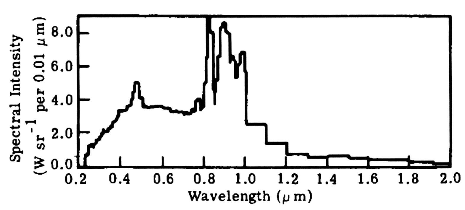
Figure 1. Intensity contours from a 5kW dc xenon compact arc lamp
Figure 2. Spectral distribution of the radiant intensity from a dc xenon lamp.
The spectral output of a xenon arc lamp is shown in Fig. 2 [4]. This data excludes the radiation from the electrodes and the quartz envelope, and it also does not measure the UV radiation that has been absorbed in the quartz envelope. The notable factor in this data is that a large fraction of the radiation is beyond the wavelength range of human visual perception, which represents major energy losses. In some sense these losses are unavoidable, because an arc is of necessity a broadband radiator as a result of the radiation processes themselves. However, it is possible to increase the amount of visible radiation emitted by including gases that have radiative transitions in the visible spectrum. Sodium vapor lamps are one example of this, although these lamps are not applicable to flashlamps because of the long initiation time. Although much of the light energy emitted from a xenon flashlamp is not in the visible spectrum, these lamps are approximately twice as efficient in this respect compared with filaments lamps, which emit large amounts of infrared radiation.
One of the flash requirements for an inset flasher is that the lamp must have three brightness levels. Arc brightness decreases rapidly as a function of arc current, such that typical steady-burn lamp intensity levels are controlled by reducing the current from High at 100% brightness and 6.6 A, to Medium at 30% and 5.4 A, and Low at 10% and 4.8 A. There is also some question about the stability of the arcs at lower currents, but no problems were found experimentally. Apparently electrode-stabilized arcs are stable over a wider range of arc currents than wall-stabilized linear arcs.
Arc sources require complex and somewhat expensive power supplies to achieve breakdown and maintain the proper arc current. The lamp discussed above has an added breakdown electrode. This electrode is omitted for less expensive systems that rely on an initial high voltage spike that provides the trigger for the breakdown in applications where the shape of the light pulse is not critical.
Pulse Length. An important aspect of flash operation is the pulse length at which it operates. The specifications for airport flashers call for a flash to provide a specified intensity of a certain number of effective candelas over a pulse length greater than 250 µ s and less than 5,500 µ s, and a flash frequency 2 times per second. There is thus an acceptable range of a factor of over 20 in pulse length. During the early part of the program this appeared to imply a fixed flash intensity with a variable pulse length, so that the time-averaged power of the flasher system would be minimized by using the shortest possible flash pulse length. Decreasing the pulse length from 5,500 µ s to 250 µ s at constant intensity seemed to lead to a 10-fold increase in lamp lifetime and lower power. The effect of shortening the pulse length on visual perception of the flash by a pilot was then investigated.
Discussions with Guy Clark, US Coast Guard retired, answered questions concerning the response of the human eye to the manipulation of the brightness and pulse length of the flash. Mr. Clark worked extensively on a "multiflick" system that replaced one long flash with multiple short flashes on coast guard buoys. The primary conclusion of this project was that the eye is an integrating sensor with a time constant of approximately 0.2 seconds. This means that the manner in which the perceived intensity is built up in the eye does not matter. The total flash energy absorbed by the eye can be in one pulse 0.2 s long or in 10 pulses 10 ms long and 200 ms apart. The mathematical formulae for computing the perceived (effective) intensity is
Where t1 is the time at the start of the flash pulse, t2 is the time at the end of the flash pulse, and I(t) is the instantaneous intensity at time t. This formula has been shown to hold for even very short flash pulses as confirmed by a white paper published by Bob Booker of SRC in 1999 in response to queries to the FAA about the effects of flash pulse length. There are upper and lower intensity thresholds associated with dark and daylight adapted eyes that also provide limits on acceptable light intensity.
This pulse length effort and later calibration work led to the realization of the importance of the use of effective candelas as defined by the above equation and used in FAA specifications. Flash pulses shorter than 0.2 s must be more intense in proportion to their pulse length relative to 0.2 s. The specification of effective candelas then becomes a specification of flash energy rather than flash intensity, always relative to a 0.2 s long pulse. This approximation is less true for pulses near 0.2 s, but it is accurate for inset flashers, which must have a pulse length less than 5.5 ms.
The commercial availability of compact arc flashlamps is driven by the need for motion illumination and analysis, where the flash pulse length must be short enough so that the movement of an illuminated object is insignificant. This trend in flash pulse length is important because these commercial lamps are designed for a pulse length on the order of microseconds to nanoseconds, whereas an airport flasher requires a much longer pulse length of 0.25 - 5.5 ms. Many of the short-pulse arc lamps can not tolerate such a long pulse length. Discussions with ARC Corp. indicate that a pulse length of 0.25 ms (250 µ s) or longer is within the capabilities of the purchased flashlamp, and this was confirmed experimentally.
Flashlamp Lifetime. Current flashlamp lifetimes are often discussed in terms of millions (106) of cycles. The standard lifetime specification for current flasher lamps is that they operate in the flasher systems for 1000 hours at high intensity. At 2 flashes/sec, this implies a needed lifetime of 3.6 x 10⁶ flashes for a standard lamp.
Discussions with ARC, the flashlamp supplier indicate that the lifetime of compact arc flashlamps are comparable with standard arc lamps. Steady-state compact arc lamps have a lifetime of about 2000 hours (compared with FAA required 1000 hrs). The flashlamp used in the current project was estimated to have a lifetime of 106 flashes or more. The lifetime of any specific lamp depends on a wide variety of the details of flashlamp operation. Equations have been developed and are available to predict the lifetime of wall stabilized arclamps, but compact arclamps are electrode-stabilized arcs, for which analogous equations have not yet been developed.
The primary goal of Phase 1 work is to improve optical efficiency, but any improvements that can be achieved will have a major impact on other arclamp characteristics. Improving the efficiency of light transfer for a specified intensity output allows a less intense source to be used. A lower intensity source can be obtained either by operating the lamp at lower current, or using a smaller lamp. Operating at lower current allows a proportional increase in lamp lifetime as a result of decreased wear on the electrodes. Using a smaller lamp allows further efficiency increases due to the still smaller source size. A smaller lamp is also less expensive to purchase and to use. The major gain will be in lifetime, however, since compact arcs have a volume power production; decreasing the power by a factor of 8 will only decrease the size of the source by a factor of 2.
Mirror. An elliptical mirror has been chosen as a result of its superior light-gathering capability and its ability to focus the light from a source through a small aperture. Creating a practical elliptical reflector for the fixture can be done in a number of ways. The standard steady-burning commercial light using a PAR-56 lamp is a complete, enclosed, glass lamp that has a parabolic shape with an aluminized inner surface and a filament at the base potted to connector pins. An alternate inexpensive manufacturing technique is to electroform the mirror; this was used to create the mirror used in Phase 1 work.
Electroformed mirrors are manufactured (e.g. Optical Radiation Corp., Azuza, CA), using a process where a mold is made and multiple copies of thin electroplated mirrors are formed by deposition onto a male mold. The mirrors are then coated for reflection and protection of the mirror surface from the environment. These mirrors have a number of advantages over aluminized glass reflectors. The mirrors are extremely accurate, a characteristic that increases overall reflectivity significantly, they easily withstand thermal shock and heat loads (rated to 400°C), and they can be easily be made to have mounting fixtures and holes. These features make them well suited to inclusion into an inset flasher light fixture. Most of the cost of mirror fabrication is in the tooling to make the mold, so for high volume, single design applications the cost can be very low. Also, the production volume needed to justify a new mirror is much less than that needed to create a new enclosed aluminized glass lamp. Fixturing additions can also easily be changed after the basic mirror parameters have been specified.
In relating the performance of an elliptical to a parabolic mirror, note that the solid angle of light captured by a complete parabola captures more than half of the total radiation from a source that radiates equally in all directions. The exact solid angle capture of a parabolic mirror depends on the focal length, f, and the outer aperture, D. For the case of an inset flasher D is limited by the size of the current underground lamp container to about 18 cm (7") diameter. Within that constraint, the solid angle captured can be increased by decreasing the focal length of the mirror, limited by the increasing divergence caused by the source size. This is an optimization procedure, since beyond a certain f the capture solid angles decrease more slowly as the parabola flares out more and more. A limitation of both types of mirror is that it is usually necessary to have a hole around the axis through which the lamp is mounted. As the focal length decreases the angle subtended by this hole increases and increases consequent light losses rapidly. The focal length chosen is a compromise between light capture and divergence angle.
Beam Optics Design. Ideally, the optical design would allow collection of all of the radiation from the arc lamp, form this light into a beam, change the area through which the light passed so that it could all be transmitted through the inset fixture aperture, and finally control the light passing through the aperture so that it was diverging at an angle of +/- 5 degrees from a centerline 7.5 degrees above horizontal, and +/- 15 degrees from a forward pointing direction. The goal of the project optical design was then threefold: 1) to collect as much arc light as possible into a beam that can be focused, 2) to focus the beam to the extent that it can pass through the fixture aperture, and 3) control the focussing so that the beam emitted from the aperture has the proper angular divergence in both dimensions. All of the beam manipulation should be done without losing any of the light that was initially collected from the source.
During preliminary work on an optimal optical design, it became clear that a parabolic reflector was not the best design choice to move the light through a restricted aperture. The easiest conceptual design technique for optics that manipulate large fractions of light from a source through an aperture is to treat the optics as if the image of the source was being moved through the optical system. The reflector of choice was not a parabola that creates a parallel beam, but an ellipse that focuses the arc spot farther along in the optical system. The focussed spot image was then treated as a new source. Light from the source image was then focussed by a cylindrical lens into a beam with the appropriate angular divergence that was as wide as the aperture was at the location of the aperture along the optical axis. Since the fixture window is much wider than high it was possible that the width of the beam might not have to be focussed down.
Performing the somewhat complex optical design was made much easier by the ability of current commercial lens and mirror manufacturers to make almost any conceivable surface quickly and cheaply. The production of the elliptical mirrors has been discussed above. Lenses can be made out of almost any material to high optical precision. Plastic lenses can be cast and polished. The high pressure output window must be glass, however, since it must withstand large hydraulic pressures from the combination of tires and rainwater. Fresnel lenses were another possibility, since the light to be used is all in the visible region of the spectrum. Glass lenses are also available, with shapes made by many different processes such as diamond turning or 3-axis CNC machining/grinding.
A schematic of Phase 1 optical design is shown in Fig. 3. The basic light transfer sequence is that the light from the compact arc source is focussed to an image by an elliptical mirror that captures a large solid angle fraction of the light emitted from the compact arc source. The light from the source image is then focused through the fixture aperture by two separate cylindrical lenses that provide the proper beam divergence in the two perpendicular separate spreading dimensions. The cylindrical lenses were f#1 lenses that were commercially available.
The spread of the beam in both dimensions was determined by the focussing lenses because the divergence resulting from the compact arc source was smaller than needed. A 1.5 mm source an average of 5 cm away from the elliptical surface implies only a 2 degree total spread. Increasing the divergence was easily done by changing the placement of the lens. Decreasing the divergence beyond that set by the source size would (and does for a parabolic mirror) require major light losses.
The cylindrical lens needed for the wide dimension of the beam depends on the width of the aperture relative to the width of the lens. If the lens can be placed near the aperture, and is somewhat smaller than the aperture, yet still captures all of the light, it can make a beam emerging from the aperture that immediately diverges. If the beam has expanded too much to fit through the aperture, the lens must focus the beam somewhat, with an angle equal to the required divergence, an angle that it assumes after it has passed its focal point.
The proposed design uses a front surface mirror to direct the light through the aperture rather than a prism. Front surface mirrors are much cheaper than prisms. They can be made to be extremely robust and efficient with current optical overcoatings.
Optics Optimization. The elliptical mirror that has been used in this project for both design and experimental work was one that was used in a previous project to focus a large amount of light from a source onto a spot. Although the goal of inset flasher design was similar, the parameters of an optimum mirror for the present application were investigated to determine whether significant improvements in mirror performance could be obtained in Phase 2 and Phase 3.
The goals of the optical design were to maximize the light collected from the source and passed through the casting aperture, and to minimize the additional divergence of collected light that was caused by the finite size of the source.
The maximum amount of light is collected by maximum enclosure of the source by the mirror. The mirror chosen has the highest solid angle capture of any of the commercial mirrors offered. One of the constraints of the manufacturing process for electroformed mirrors is that the mirror surface always be divergent so that it can be removed from the mold; this limits the solid angle that can be captured by the mirror. Another limitation to the collection angle is that the light must be able to be refocused by a lens. As the solid angle collected by the elliptical mirror increases, so does the solid angle of light that is focused. Commercial lenses are not made with a f# less that approximately 1, so that the light that can be captured by a lens is limited to a 45° angle. This is approximately the angle of light that is focussed by the mirror currently used in the project, indicating that not much more light can be collected with a different mirror.
To minimize the effect of a finite-sized source, the mirror should be a large as possible. The size of the source is set by the size of the compact arc. The primary constraint on mirror size is that it must fit into the inset flasher can, which is about 30 cm in diameter, but FAA specifications limit the mirror aperture to 18 cm (see background section). Work will be done in Phase 2 to determine whether the light collection gains that result from a larger mirror will justify the additional cost of a larger mirror. An additional advantage of a larger mirror would be that the focussing would be better. This would allow the focus of the mirror to be farther from the source and the solid angle smaller, also allowing a larger solid angle from the mirror to be collected by the collimating lens.
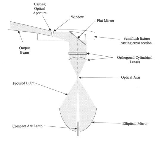
Figure 3. Schematic of overall optical design, side view cross-section.
The conclusion from this analysis is that better mirrors than that used in Phase 1 can be obtained, but that increased light collection will not be large; the mirror used in Phase 1 is adequate to demonstrate project feasibility.
Modeling. A series of MathCAD programs were written to perform ray tracing analyses of the current and the proposed flasher optical systems. These programs analyzed the interaction between the size of the source, the mirror, and the focussing optics with respect to formation of the specified beam.
The Flasheff.mcd program performed ray tracing as a function of source location to a generic elliptical mirror used in the project and to a cylindrical focussing lens. Based on the parameters of the specific mirror used experimentally (Model EP112, Optical Radiation Corp, Azusa, CA), this program was used to specify the cylindrical focussing lens and to evaluate qualitatively and quantitatively the effects of finite source size. It was also used to evaluate the performance in the system of an elliptical mirror with different optical parameters. This program was used to generate related programs that performed a similar analysis of a parabolic reflector system.
Light was assumed to be emitted from a small volume of space near the focal point of the elliptical mirror. A small source size is a good approximation for the flashlamp that was used for the project, but not for flashlamps currently used. The size of the arc source was small compared with the focal length of the mirror. In the program, the mirror has arbitrary parameters, defined for initial purposes to be those of Thoughtventions's pre-existing mirror. A cylindrical lens of arbitrary focal length, width, and thickness was located so that it focused the image of the source from the mirror into a parallel beam. The position of the lens could then be moved along the optical axis to obtain a beam of any specified angular spread. The size and focal length of the lens determined the size of the output beam.
The program allowed calculation of the angle of the limiting rays from the source that could be captured within the desired angular envelope emerging from the light fixture. More importantly, it allowed calculation of a similar envelope for any source point away from the focus of the ellipse, but within the finite size of the source. In this way the solid angle of light captured from a finite sized source and transmitted into a spreading beam could be estimated.
A variety of tests were performed on the model to verify its accuracy. The model was first tested by performing ray traces from a source at the focus of the ellipse. The rays were found to be focused at the opposite focus of the ellipse, and then refocused into a parallel beam by the cylindrical lens as expected. This was true for all ray angles from the source. The rays were followed from the source, reflected off the mirror, refracted into the lens, and refracted out of the lens. Graphs of the rays relative to the outline of the optics showed when the mathematics diverged and whether the marching parameters were behaving properly. Baseline cases of overall light collection confirmed integrating source light collection programming. A number of non-converging cases were identified and corrected.
Efficiency Analysis. The experimental demonstration of a significant improvement in optical efficiency must be complimented by a detailed and accurate assessment of the improvements in optical design that are responsible for this increase in efficiency for an inset flasher that a compact arc offers compared with the standard helical arc flasher. A further subtask is to understand the physics of the light losses of both the steady state lights and the flasher systems that are currently used in airport lighting systems.
Light Collection. A fundamental characteristic of airport approach lighting is that a typical fixture emits light into a fairly small angular envelope centered on a specific direction that forms a guide to landing aircraft. Since unfocussed light sources emit in all directions, a reflector placed behind the light source is used to collect a large solid angle of the radiation from the source and transfer it into the desired direction. The standard fixture uses a parabolic aluminized reflector (PAR). A parabolic mirror collects light from a point source at its focus and ideally focuses it into a parallel beam. Of course, the parabola is open-ended, so if the source is even with the end of the mirror, a solid angle of at most 2π can be collected from the source - half of what is radiated by the source. Significant additional light is lost by being blocked by the base of the lamp and never intercepted by the reflector. However, usually the mirror extends significantly past the light source, so that a total of about 50% of the light emitted can be captured into the beam for a reasonable divergence and a small source size. As a result of the shape of a parabola, the distance from the parabolic reflector surface to its optical axis increases rapidly as the mirror becomes longer along the axis, such that the solid angle of light captured by the mirror is limited by the overall size of the mirror.
The effect of light source size on light collection was quantitatively explored using the MathCAD model. The total light collection of a parabolic mirror from a line source was calculated for a number of cases, confirming the approximate light collection discussed above. For example, the light collection from a 5 cm diameter aperture parabolic mirror with a focal length of 1 cm and a 10 mm long axial light source centered at the mirror focus. The light collection solid angles from each of 20 points along the source was calculated and summed to give a total solid angle fraction (out of 100%) of 46 %.
An elliptical mirror is fundamentally different from a parabolic mirror in that it is meant to fully enclose the source. Ideally, an elliptical mirror can entirely surround a source to focus its light at the other focal point of the ellipse. Practical ellipses that are used for light transfer still enclose quite a bit more of the emitted solid angle from the light source - typically 70%. This represents almost a 50% gain relative to a parabolic mirror, but it assumes that the light focussed by the elliptical mirror can then be refocused into a beam of the required divergence.
An inherent characteristic of real light sources is that the physical structures that must be used for supporting the light source also obscure some of the light from the source. An arc source radiates primarily from the open sides of the arc volume between the two electrodes. One electrode is flat, and the other is conical. To achieve maximum light capture, the flashlamp is oriented with the conical electrode nearer to the mirror base. An elliptical mirror captures significantly more of the radiation from a compact arc source compared with a parabolic reflector.
The solid angle subtended by the focussed light at the imaging focus defines the size that the cylindrical lens must have to capture all of this light, given its focal length. In the present case the cylindrical lens must have a f# (ratio of focal length to diameter) close to one; such lenses were readily commercially available, and were purchased and used experimentally.
Light Losses Due to Finite Source Size. The most difficult effect of the process of light collection to quantify was the effect of a finite source size. It is well known that the larger the source is, the larger will be the divergence of a beam formed using this source to supply light to the beam. For an infinitesimal source and ideal optics, the light transfer efficiency is determined by the solid angle of light emitted by the source that is focussed into the beam. For a source of finite size, the solid angle of light captured by a mirror (and transferred to a beam of specific divergence) is different from different parts of the source. An accurate analysis requires a three dimensional integral of solid angle contributions over the full volume of the source.
When the source is of comparable size to the mirror, the light reflected from the parts of the source farthest from the focal point often have a greater divergence than that acceptable for the output beam. A light source exactly at the focal point of a parabolic mirror is reflected into a parallel beam emerging from the mirror. The farther the light source is from the focal point, the more the light diverges from the optical axis of this parallel beam. Since the angle of incidence and angle of reflection are identical for light reflected by a mirror, the angle between a light ray from a source element and a ray from the focal point whose apex is the reflection point on the mirror determines the divergence of the light from this source element relative to the parallel beam.
An important factor for increasing the efficiency of current semi-flush flasher systems is the decrease in source size associated with changing from the standard helical flashlamp to a compact arc lamp. The standard flashlamp uses a helical flashlamp that is approximately 25 mm in outer diameter, and 32 mm long. One of the peculiarities of this lamp is that the arc itself is wrapped around the centerline of the lamp, so that when the lamp is centered at the focal point, none of the light is actually emitted from the focal point, only around it. The compact arc used in this project has an arc size of only 1.5 mm - a factor of 20 smaller size. For a reflector large compared with 25 mm this makes little difference, but the reflectors in an inset flasher must be small.
One way to avoid this problem for a standard arc lamp is to use a linear lamp, where the line can be focused into the small divergence direction of the beam. This is the choice made be the current ADB inset flasher fixture. Although this is an effective technique for one dimension, large light losses occur for the long dimension of the lamp. Flat mirrors are used for the end reflectors, resulting in a loss of about a factor of 6 (30° out of 180°) compared with a compact arc that will lose little radiation upon focussing. For the helical lamp efficiency comparisons depend on the size of the reflector.
The MathCAD model was used to assess the divergence associated with a 1.5 mm diameter source (the arc used for the project) in the proposed optical design. The optical configuration was the specific mirror used in the project, and a f#1 cylindrical lens with a focal length of 2.9 cm. The cylindrical lens was place to focus the light from the elliptical mirror into a parallel beam. Rays at various angles from the source were traced through the system to determine the divergence angle of these rays from the lens. Rays from a source point at the focal point of the mirror were exactly parallel for all angles. The source location was then moved away from focal point to investigate the divergence of rays from a finite-sized source. The distance from the focal point was up to 1.0 mm to investigate the capture of rays from the 1.5 mm diameter arc source.
The divergence angles of the rays for different positions in the source and different ray angles is shown in Fig. 4. The standard for light capture is that it fall within a +/- 5° output divergence angle as required for the narrow part of the inset flasher beam. It can be seen that at a source location +/- 1.0 mm above and below the focal point, almost all of the light from the source point does not fall within the desired divergence. However, for a source location +/- 1.0 mm along the optical axis relative to the focal point, almost all of the light from the source point is within the desired divergence. That the results are not symmetric with respect to the location of the light relative to the mirror focus arises from the inherent asymmetry of the mirror. That most of the light from the 0.75 radius arc source is captured is seen by the plot of rays from 0.5 mm above the axis, which are almost all within the required divergence angle. The conclusion is that the elliptical mirror used in the project is a highly efficient light gathering device for the size of the arc source used and the beam divergence required. It is also true that the use of sources much larger than a few mm will result in much greater light losses.
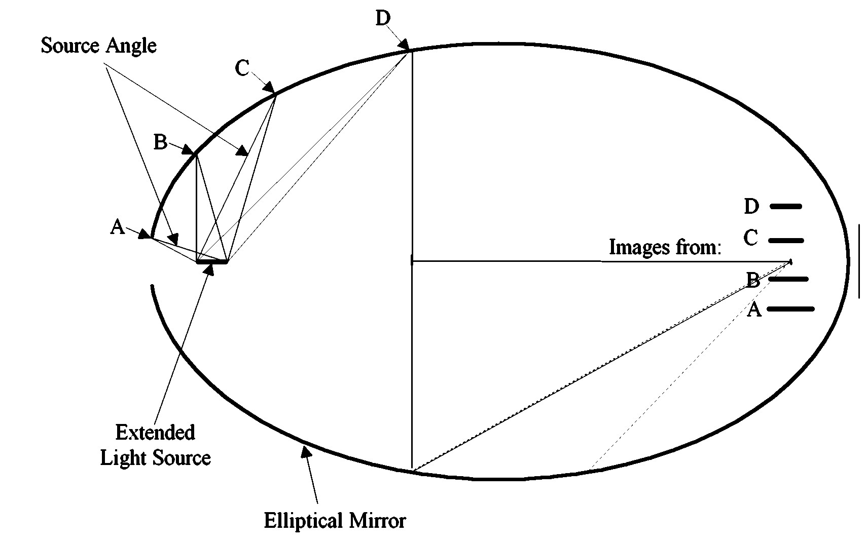
Figure 4. Divergence of rays for source light positions near the focus of an elliptical mirror.
Another aspect of the implications of a light source with a finite size for an inset flasher is the relation of the source size to both the optics size and the aperture size. An illustration of the comparison of the light collected by a parabolic versus an elliptical reflector is shown in Fig. 5. Two systems designed for the same aperture, source size, and beam divergence are shown in the figure. Both systems are scaled to the size constraints of actual 150 W filament light sources. As can be seen, the light collection of the parabolic reflector is limited by the small aperture, whereas the elliptical reflector can collect more light because it can focus it to a smaller size. The divergence increase resulting from focussing the source to a smaller size is balanced by the larger size of the mirror. The elliptical mirror system thus is able to increase the collected light by a factor of 1.5 to 2 compared to the parabolic mirror system, depending on the details of the optics. This is one type of efficiency gain associated with changing from a parabolic to an elliptical mirror, appropriate only to the case of a limiting aperture whose size is the same order of magnitude as the size of the light source. This is the case of current inset flasher units, where the vertical aperture is only on the order of 25 mm wide.
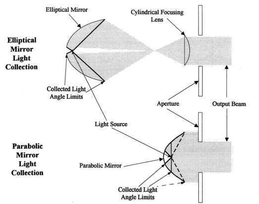
Figure 5. Schematic of the light collected and focussed through an aperture by an elliptical and a parabolic mirror.
Optical Energy Efficiency. The goal of this task has been to improve the overall optical energy efficiency of the flasher lamp and optics. This was primarily done by decreasing the size of the arc source to decrease divergence losses through the optics, and by collecting and using a larger fraction of the light output from the lamp. The proper measure of system efficiency is the total light energy output relative to the electrical energy input. Although many of the process efficiency factors can not be changed it is instructive (and never discussed in equipment catalogs) to understand how poor the actual energy efficiency is. Given in Table 1 are approximate numbers for a steady burning lamp. These numbers include the improved design in this task; standard light collection is a factor of 2-5 lower than the focussing optics losses given below. This is a result of inefficient collection and manipulation of the light into the desired output beam. The larger arc source size of standard lamps also leads to major losses because the inherent divergence of the light passing through the collimating optics leads to major light losses. Even with improved optics, the overall energy efficiency is extremely low.
Table 1. Power losses for arc lamp radiant power delivery.
...............................................................................Loss Factor..............Power(Watts)
Arc Lamp
Electrical power..............................................................................................200
Electrical-radiant conversion.................................15%...............................30
Wavelength band reduction...................................5%..................................1.5
Parabolic reflector solid angle capture.................50%..................................0.75
Focussing optics losses.........................................70%..................................0.6
Total optics surface reflection................................70%..................................0.4
Light Source Efficacy. Efficacy is a term used in illumination engineering to relate the electrical power dissipated by light source to its visible light output power, and is typically given in lumens per electrical watt. In some sense this number represents the luminous efficiency of a lamp; how efficiently the lamp power is turned into visible light. The efficacy number thus includes a host of efficiency factors that describe the transfer of electrical power dissipated in the lamp to the emission of light within the light bandwidth visible to the human eye. Arcs and filament light sources are fundamentally different in the mechanism by which they produce light; they also have significantly different luminous efficiencies. Standard arc lamps have an efficacy that is more than a factor of two greater than that of filament lamps, largely as a result of the much greater amount of infrared radiation emitted by a filament lamp. Quantitatively, a 100 W halogen filament lamp would have an efficacy of 0.2 lumens/W, vs. a 100 W arc lamp with an efficacy of 0.47. This increase in efficacy is the first type of efficiency gain resulting from the change from filament to arc lamps and forms a major motivation for this changeover in cases where other factors make it practical. However, arc lamps typically require a more complex electrical system for operation.
Overall Efficiency Assessment. The above analysis indicates that elliptical mirrors have significant light collection advantages over parabolic mirrors when the light must be directed through a relatively small aperture with a narrow divergence. The quantitative gains for an elliptical vs. a parabolic mirror depend on the details of the application, but can be as much as a factor of 2-3 for a case such the inset flasher fixture of this program.
Flasher Testing. The flasher optics and arc lamp assembled were extensively tested for intensity output. Initial flash testing was done visually; final measurement were performed using the calibrated photodetector and neutral density filters that prevented saturation of the detector at the very high intensities measured.
Flashlamp testing began using only the trigger discharge. This provided enough light for focusing and exploration experiments to be done in a dark room. Higher intensity experiments were next performed using a 7 µ f capacitor as the main drive capacitor, as the optics and the electrical system was steadily improved over a number of flash test iterations. Higher power experiments were next performed, increasing the voltage on the 7 µ f capacitor. There were five charging voltage settings available for the main capacitor, and only the top four were used: 61, 123, 184, 250, and 306 V. The arc lamp is designed to operate at 300 V, so the lowest voltage settings were presumably inefficient. Finally, high power experiments were performed using the 230 µ f capacitor and then the 2000 µ f capacitor. A limited number of experiments were performed at the highest voltage setting using the 2000 µ f capacitor. Probably close to 1000 shots were fired on the flashlamp; approximately 100 computer data sets of simultaneous photodetector voltage and circuit voltage were taken during flash intensity testing.
As the intensity data were taken, it was not clear whether the beam intensity was appropriate to the beam spreading specifications. The light emerging from the aperture has a fixed energy, some of which was probably lost passing through the aperture. The light energy of the beam is a light intensity times a pulse length. The light intensity in turn is spread over an area at the screen that is determined by the beam spreading characteristics. A beam covering more area will be less intense, whereas a beam covering a small area will be more intense. The beam that is appropriate to FAA specifications must have a minimum intensity over a specific area. If the beam is has the appropriate energy, but is too small, then once it is expanded, its intensity may be too low. For this reason beam intensity measurements must always be accompanied by beam profile measurements to determine whether the beam meets specifications.
Accurate creation of the proper beam will depend on detailed beam intensity profile measurements. Adjustment of the optics to maximize beam intensity must result from iterations with these profile measurements. This means that either an array measurement device must be built, or that detailed beam profile measurements must be made after each optical adjustment.
The beam profile was only approximate, and extrapolation must be done to estimate what flash power is associated with the formation of the proper beam intensity and area. For this reason, an approximate beam area was set up and beam profile measurements were taken from which the flash energy was estimated that would be needed to create the proper beam. This beam energy determines the estimate of the efficiency of the optics that is compared with current technology.
Flash Beam Profile Measurements. Once the beam divergence had been created visually, and the flashlamp circuitry and photodetector completed, the two-dimensional profile of the beam normal to the beam axis was measured to determine the actual beam spreading and intensity profiles. A wooden screen approximately 1.2 m square was mounted perpendicular to the beam axis, and approximately centered on the beam. A few flashes on this screen allowed visual location of the approximate center of the beam. This center was marked and a set of 0.95 cm diameter holes spaced 10 cm apart were drilled in the form of a + sign. Nine holes were drilled away from the center hole in the + and - x and z direction, making a total of 37 holes. The number and spacing of the holes were such that they extended well beyond the edge the visible beam, but were numerous enough to provide a detailed profile of the beam in both the narrow and wide dimensions. The photodetector was mounted on a tripod behind the wooden screen and for each measurement the detector active area was aligned with a measurement hole visually from the front of the screen so that the detector had an unobscured view of the flash. The screen with its holes was not moved at any time, providing a fixed location reference for beam profile measurements. The measurements were very repeatable. The main capacitor voltage for these profile readings was 123 Volts; the flash energy was estimated to be approximately 11 Joules.
For a beam spreading +/- 5° in one dimension, and +/- 15° in the other dimension at from a small diameter 2.0 m away, the approximate beam dimensions would be 35 cm wide in the narrow dimension, and 1 m wide in the broad dimension. The beam is somewhat smaller in both dimensions than the desired beam. Some of the light from the source was cut off of the beam by the aperture as a result of constraints on the arrangements of the lenses and size of the apertures. The casting apertures are not totally suited to the Phase 1 design, since it is made for 2 steady bulbs in the head, and consequently has two apertures separated by a wide strut. The Phase 1 optics have transferred the light through one of these two apertures. The rapid drop in light intensity on either side of the wide dimension of the beam is indicative of the fact that some of the light is being cut off by the sides of the one aperture. Later, the casting was removed, and the size of the beam measured visually. It was found that the narrow dimension of the beam was slightly larger than the narrow dimension of the aperture, so that some energy was lost in the narrow dimension as well. Since the energy efficiency of the system is a critical issue for Phase 1 feasibility, at the end of the program more beam profile measurements were performed.
For the next profile test, the casting was removed and the two fresnel lenses were set up to give a narrow beam in both dimensions. A much larger mirror was used to steer the beam to be sure that no light was lost off the edges of the mirror. The beam target scanning screen was left in the same location and the beam was steered by the mirror to try to center the beam on the target crossed holes. A narrow beam was indeed formed. The notable aspect of these measurements was the decreased intensity of the beam. In order to focus the beam, the lenses had to be moved farther from the focused image of the elliptical mirror, and some of the light was lost off the edges of the lenses. The lenses are f#1 lenses, with a 5 cm aperture and a 5 cm focal length. To capture all of the light energy the lenses were moved so that they focussed the light into a nominally parallel beam. The divergence of the light is then a result of the divergence associated with the finite size of the source and the optics.
The beam energies can then be compared for the case of the beam directed through the aperture, and the case of the beam where almost all of the beam energy is captured. The energy of the beam is a sum of the intensity over the beam area. For the wide dimension of the beam, the beam energies are approximately the same - the lower height of the aperture case is compensated by the added intensity of the parallel case. For the narrow dimension, the profile measurement of the parallel case was taken off center, but normalized to the 0.68 MLux peak value, there is about twice as much energy in the narrow dimension of the beam for the parallel beam case compared with the aperture case. This provides a quantitative estimate of how much energy is cut off by the aperture - and that could be regained by a wider and slightly higher aperture, both of which can easily be designed into an improved aperture. The same improvements can be gain by making the apertures of the lenses slightly larger - an easy matter for fresnel lenses.
An estimate can then be made of the intensity level associated with a beam 35 cm wide and 105 cm long at the screen location. This is the FAA specified nominal beam with a divergence of 5 degrees in the narrow dimension, and 15 degrees in the wide dimension. It is estimated that the beam intensity without lost light would be close to 0.3 MLux, based on the measure profiles and the corrections for beam energy lost through the aperture.
Flash Electrical Energy Measurements. Knowledge of the electrical energy input into the optical flash was critical for comparison with current inset flasher systems. The energy stored in the main capacitor is calculated by the classical equation CV2/2, but this energy could be dissipated in many ways not related to the optical flash. In an effort to accurately know the energy of the flash, the time dependent current and voltage of the flash was measured. The voltage was measured at various points around the flashlamp circuit and an instantaneous current measurement was made using a shunt.
These measurements agree with the performance of the circuit and the flashlamp. The light signal output has the same temporal shape as the flash current and power, indicating that there are no noise effects modifying the signal from its true value. The close agreement between calculated and measured flash power gives confidence in the assignment of a specific flash energy to an output light level, which is critical to the assessment of the overall energy efficiency of the optics as compared with standard equipment.
High Flash Power Experiments. Once a beam profile had been achieved the driving energy of the flash was increased, changing the main capacitor voltage from 123 V, to 184 V, 250 V, and finally overdriving the lamp with 306 V. The flash energy increases as the square of the voltage. The lamp appears to be less efficient at lower operating voltages, which may be why the manufacturer recommends that the flashlamp be operated at the higher voltages. Note that a maximum illumination level of 1.6 MLux was reached at the highest capacitor drive energy.
Intensity Calculations. To satisfy the FAA specification for an inset flasher operating at the highest intensity level, the illumination goal for the Phase 1 flasher unit is a minimum of 8,000 and a maximum of 20,000 effective candelas intensity in a an oval beam spreading pattern of +/- 5 degrees in one dimension, and +/- 15 degrees at right angles to the thin dimension. In order to translate this illumination level into units that will be measured by a photodetector, candelas must be converted to an equivalent light flux per unit area - lumens/m2, or lux. A candela equals 1 lumen/steradian, and a steradian (sr) equals 1/4π x total spherical surface at a given spherical radius. For a source radiating from a point, the area of a sphere with a radius of 2 m is 4π (22) m2 = 50 m2. Thus 1 sr covers and area of 4 m2 at a radius of 2 m. At a radius of 2 m, 20,000 cd = (2 x 10⁴ lm/sr)/(4 m2/sr) = 5 x 10³ lm/m2 = 5,000 lux. Thus, a light intensity level of 8,000/20,000 cd translates into a measurement of 2,000/5,000 lux at a screen 2 m from the expanding beam. The two meter screen is taken as a data station since it is far enough away from the light source that all internal changes in the beam due to focusing have disappeared.
The photodetector measures instantaneous lux, so the beam pulse measurement must be converted from an absolute measurement to effective lux, equivalent to effective candelas. Effective candelas are defined as:
Ie = [∫ I(t)dt]/[0.2 + (t2 - t1)]
where the integral is performed from time t1 to t2. For a 500 µ s square pulse of intensity Io, Bloch's equation gives
Ie = [(5 x 10⁻⁴)(Io)]/(0.2) = (2.5 x 10⁻³)(Io)
Therefore the intensity needed for a 20,000 cd effective intensity at a radius of 2 m is:
Io (r = 2 m) = (5 x 10³)/(2.5 x 10-3) = 2 x 10⁶ lm/m2
For a 500 µ s pulse a light pulse intensity 400 times the measured steady state level is required to meet the effective candela requirement. Direct sunlight gives about 145,000 lux using the light meter, so for a 500 µ s light pulse, to achieve a 20,000 effective candela measurement, an intensity 20 times that of daylight is needed. To satisfy the FAA minimum high intensity flasher requirement of 8,000 cd, an intensity level of 8 x 10⁵ lm/m2 is required at the screen for a 500 µ s pulse.
The beam intensity and profile measurements have indicated that an FAA specified nominal beam generated in Phase 1 experiments has an intensity of 3 x 10⁶ lm/m2. This beam was generated with a flash energy of 11 Joules. The FAA minimum intensity is 8 x 10⁵ lm/m2, indicating that a higher flash energy is appropriate to meet the beam intensity specifications. Based on the data for flash peak intensity a factor of 8/3 = 2.67 increase in beam intensity would require an increase to approximately 35 joules in flash energy. It is concluded that the experimental optics generate the FAA specified beam with approximately 35 joules of flash energy, approximately half the flash energy of current inset flashers, as discussed below.
Comparison to Commercial Lighting. Commercial light sources are the benchmark for the feasibility assessment of this project. The primary motivation for this project has been the limited performance of current inset flasher systems. Current steady-burning airport lighting also provides a benchmark for optical efficiency tests in terms of collection efficiency from finite-sized sources and absolute relative output intensities relative to the design of this program. At the end of the program the parameters and performance of the steady-burning fixtures were clear, as well as the energy used to meet the minimum FAA photometric specifications. Until the ADB unit is delivered, it can only be assumed as probable that these units meet specifications; calculations support the fact that they do - inefficiently.
Steady Burning Intensity Comparisons. One hard point of reference for steady-burning inset fixtures was provided by ALSTOM, Flight Light's major European industrial partner. They have a 3 lamp design that meets the ICAO Approach, Side Row and Threshold Wingbar specifications. The lamps are 105 watts each, and the performance produced is an elliptical cone of dimensions 10 degrees in the horizontal by 5.5 degrees in the vertical with an average intensity of 20 000- 22 000 cds. This envelope is slightly different than that specified by the FAA (15 degrees in the horizontal by 5 degrees in the vertical), but it is close enough for direct comparison. The lamps are halogen filament lamps, which have a luminous efficacy of about 0.22 lumens/watt electrical. Thus, the three lamps have an output of (315)(0.22) = 69 lumens focussed into the beam envelope. Taking 20,000 cd as the output intensity, and calculating a 15/10 higher light output needed for the wider FAA angle implies that a light output of 103 lumens; 472 W of lamp power is needed to provide the FAA specified beam pattern at an intensity of 20,000 cd by the optics in the inset fixture. In this case, the optics consist of a parabolic back reflector and some lensing performed by the output windows. The fixtures are similar to that shown in Fig. 6 for a 2-lamp inset fixture.
Figure 6. Photograph of a typical steady-burn inset flasher head and optics.
These numbers can be used to infer the performance of an equivalent flasher fixture. Assuming the same source size and optics, a flash lamp has a significantly higher luminous efficacy - 0.47 lumens/electrical Watt. Thus (472)(0.22/0.47) = 220 watts of arc lamp power are required to provide the 20,000 cd FAA beam. A 220 W arclamp would then be sufficient to provide the specified beam - assuming that it had the same size and same optics. A compact arc lamp would certainly provide the small source size, but probably could not provide the lifetime of the comparable, although higher energy filament lamp.
Translation of this performance into flash performance must return to the issue of effective candelas. The inset flasher must flash 2 times per second for a duration of between 0.25 and 5.5 ms. The High Intensity beam specification for the inset flasher is a minimum of 8,000 effective cd and a maximum intensity of 20,000 effective cd. The steady state fixture would provide 20,000 cd with a 220 W arclamp, or 8,000 cd with an 88 W arclamp. Effective candelas are calculated relative to the eye's time constant of 0.2. Shorter pulses must be proportionally more intense. This means that the flash intensity specification is actually a flash energy specification relative to a light intensity at a pulse length of 0.2 s. Thus, the lamp power required to generate an 8,000 cd intensity pulse for a duration of 0.2 s specifies the flashlamp energy for any shorter pulselength, assuming the arc efficiency is unchanged by the pulselength, which is a fairly good assumption. The 88 W arclamp then translates into a (88)(0.2) = 17.6 Joule flash driver energy. The conclusion is that about a 20 J flashlamp energy is needed to give a 8,000 effective cd output beam of FAA specifications. Because the filament source is relatively small, (5 mm or less), the optics are relatively efficient.
Flasher Intensity Comparisons. There are two commercial semi-flush flashers that have been studied. A current model, the IN-ATF, manufactured by Thorn Light, (Europe, DME US rep.), and an older model manufactured by ADB (Columbus, OH) and installed at a few airports in the US. A manual for the latter was supplied by the FAA, from which information on its construction and operation were obtained. The critical optical characteristics of these units are the power and geometry of the flash lamp, the geometry and size of the reflector, and the properties of the prism/window.
Characteristics of the ADB unit were obtained and deduced from the manual. The flashlamp power is the same for both the above ground (Type 1) and the inset (Type 2) flasher. Flash power is given as 120 W with a peak current of 75 A. For two pulses per second, this implies a lamp energy of about 60 J. A cylindrical parabolic reflector is used to collimate the light emerging normal to the axis of the linear flashlamp. This collimation provides the vertical divergence of the light from the fixture, while the horizontal spread is supplied by the end mirrors. Presumably the window apertures cut off a significant amount of the light from the lamp in both the horizontal and vertical directions. It should be noted that the above-ground flasher uses a parabolic reflector, and the U-shaped flashlamp is inserted from the side of the reflector.
Based on the geometry of the fixture, one can estimate the light collection efficiency. In the horizontal direction a good approximation is that the light within the specified 30° angle horizontal spread angle is part of the beam, but that there is no concentration effect at all. Each element of the lamp radiates through 180° (assuming a back reflector), so that 1/6 of the radiation parallel to the lamp axis is included in the beam. In the horizontal direction, about 60 % of the light is captured by the parabolic reflector behind the lamp. Probably half of that is lost through the aperture, so that 30% of the light emitted normal to the lamp axis is captured into the beam. Total light collection is then on the order of 5%, and probably less.
Buried in the manual are the details of the flash driving mechanism and pulse length. The lamp is driven both by capacitor discharge and 120 VAC line current. Relatively small, high voltage capacitors fire through the lamp initially to form a low-resistance plasma, after which the primary lamp power is supplied from the main power line. The pulse length is then primarily determined by the 60 Hz power sine wave. One cycle is 18 ms, and a half wave is 9 ms, and the period where the voltage is above half voltage is about 5 ms; this, then is the pulse length, initiated by the capacitor discharge.
Information on the Thorn Light unit was obtained from their web site; it is stated to use a 60 J flash lamp, and presumably meets the ICAO specifications. This is comparable to the ADB unit. The optics arrangement in their fixture is unknown.
It is concluded that current inset flasher units use a pulse energy of about 60 J, a number that can be used for efficiency comparisons with this project. The above calculation based on steady burning lamps (smaller source and better optics) imply that a flashlamp of equivalent efficiency would use about 20 J. This indicates the potential efficiency gains for an improved inset flasher fixture. It is also consistent with the added light losses in the flasher unit that are a result of less efficient focussing of the light from the flash.
Near the end of the reporting period the FAA authorized the purchase of a complete ADB unit under the SBIR contract. The unit was scheduled for delivery 1-3 weeks before the end of the contract, but that actual delivery was 1 month after the end of the project. It is unfortunate that photometric measurements could not be made on this unit.
Flash Technology was also supposed to provide one of its standard above-ground flasher units for testing in this project. This unit was not delivered as a result of some unknown internal company decision.
Feasibility Assessment: The determination of overall feasibility for Phase 1 is based on a combined assessment of whether 1) the design meets FAA specifications, 2) major gains in lighting energy efficiency can be achieved, 3) the components are compatible with current manufacturing capabilities, 4) the overall cost of the fixture is comparable with current systems. These issues have all been resolved in Phase 1.
Meets FAA Specifications. The appropriate FAA specifications for an inset flasher are given in the background section. Of these the most difficult to meet is the effective intensity specification. Photometric measurements of the Phase 1 flasher system have demonstrated that the 8,000 cd minimum effective intensity has been achieved for a beam emitted through a standard inset flasher with the proper angular divergence. The optics also meets the FAA physical and electrical specifications. The only specification that has not been experimentally demonstrated is the 1000 hr lifetime of the flash. That this specification can be met is strongly implied by assurances of the lamp manufacturer that the compact arc flashlamp has an equivalent lifetime to the linear lamps
now in use. The lamp can be derated if additional lamp lifetime is needed. The Phase 2 prototype is expected to meet FAA specifications without difficulty.
Lighting Energy Efficiency. A lighting energy efficiency improvement of approximately a factor of 2 relative to current inset flasher systems has been demonstrated experimentally and by analysis. The efficiency gains occur as a result of greatly improved light collection in the formation of the specified output beam. The improved light collection is due to the combination a much smaller light source in the form of a compact arc lamp, and focusing optics that allow the light to be efficiently transferred through the aperture in the inset flasher lid.
Compatibility with Current Manufacturing Techniques. Given the design chosen for the prototype optics, the issue of the compatibility of this design with current manufacturing techniques was addressed. An associated issue is the requirement of mil spec parts that will meet the extreme environmental conditions seen at different airports. The electrical equipment is all standard, so there should be no problem with this equipment. The manufacturing of the components, circuit boards, potting, insulation, and connectors is all well established and commercially available, in mil spec type parts, as well. As much of the equipment as possible will be commercial off the shelf items.
The inset top casting will be obtained from Alstom, who already make these parts (one was used for Phase 1 testing) and currently supply Flight Light with this and related types of equipment. These castings are already certified and in use at airports for inset steady burning lights. They are designed to operate during rollover, snow plow impact, and the variety of unusual environmental conditions that are encountered in airport lighting applications. Because multiple bulbs are required for the steady-burn inset fixtures, a model with a single aperture appropriate to this application is not available. Eventually a single-aperture casting will be made and certified.
The fixture can will be standard issue, as will all of the external fittings that are now in use.
Techniques for encapsulization/hermeticity of the optics will also be standard for airport fittings. The flashlamp, mirror and optics are all compatible with the requirements of airport lighting, including mounting for vibration/shock isolation. The flashlamp mount is standard, as are the other lens and mirror mounts. The adjustments/design for focussing is also standard. There appear to be no problems with the manufacture of the inset flasher design.
Overall Cost. The overall cost of the fixture will be comparable with current systems. Considering the optics first, the flashlamp cost will be the same or cheaper than the lamps currently used. The parabolic mirror will probably cost the same or cheaper than the multiple mirrors now in use. One major cost saving will be that prism that is currently used will be eliminated and replaced by a simple window. The prisms are specially made and are much more expensive than a simple glass window. The lenses that are used in the design are inexpensive, commercial items and should not contribute significantly to the overall cost. The lens and mirror mounts should not be expensive, once their design is completed. The electrical components will be both cheaper and newer as systems and individual parts. Current electrical design techniques that incorporate many features into circuit boards make the overall electrical circuitry much cheaper. There is a real possibility that COTS electrical equipment can be directly purchased from Flash Technology and used with minor modifications.
The can and casting will be the same cost as current inset flashers. In-fixture monitoring is not currently done, so adding this feature will increase the cost somewhat. This is a cost that is well worth paying in exchange for decreased maintenance requirements. Another cost that must be tolerated, but is the same for old and new fixtures is the cost of sealing the optics. The cans can be filled with water, so the optics must be put in a hermetically sealed compartment by themselves, with a feature that allows replacement of the flashlamp. It is probable that the entire optics can will be replaced in the field, and that the flashlamp will then be separately replaced and the unit ready for replacing another unit. Overall, the cost of the new inset flasher is expected to cost the same or somewhat less than current models, depending on the lowered cost of the electrical systems and the added cost of installing a monitoring system.
It is concluded that feasibility of the improved inset flasher has been conclusively demonstrated.
Phase 2 Plan: Phase 1 has resulted in a basic overall optical, electrical, and physical semi-flush flasher design, together with an alpha prototype flashlamp and optical design. This work provides the foundation for the design of a Phase 2 beta prototype, which will be as close as possible to the commercial product. The beta prototype will consist of a complete fixture, including optics, electrical/electronic systems, and high strength cap consistent with current standard flasher fixtures. It is expected that the optical design will be very close to that developed in Phase 1, adapted for ease of manufacturing or assembly. Cost will also be a factor in the design. During Phase 2 the beta prototype device will be fabricated and tested for performance characteristics and environmental constraints. This will be a joint project between Thoughtventions and Flight Light and its commercial partners.
Phase 2 Preparation. The bulk of the work done in preparation for Phase 2 is described and reported in the Phase 2 proposal. Phase 2 work will center on developing the engineering systems for the inset flasher. The primary development issues to be addressed have been identified (not in order) as: Optical mounts, Commercial electrical systems, Heat dissipation, Casting details, Failure monitors, Optical component sources, Flashlamp lifetime, Systems engineering, Manufacturing development, and System certification. An overview of the Phase 2 tasks is as follows.
The first Phase 2 task will be the engineering design of the optical train. The lenses will be mounted together in a tube. The entire optical chain will be mounted in the flasher can as a sealed unit, including the flash lamp and the elliptical mirror. A key element will be to design the optics so that the flashlamp can be easily replaced. To change the flashlamp, the optics will be removed and the lamp removed and replaced through the end of the elliptical mirror. An appropriate mount with three struts for spatial stability will be fabricated so that the end of the flashlamp can be plugged into it inside the ellipse, and then the connector fastened on the end. The position of the arc must be repeatably and accurately placed at the elliptical mirror focus.
The question of how to handle the heat dissipation of the flashlamp has been addressed. First, it should be recognized that the heating problem is significantly eased by the decreased lamp wattage associated with the more efficient optical system. It is expected that the heating will still be significant; the degree of heating will be quantified in Phase 2 work. The heat can be carried away without damaging the optics by using a chimney effect. A flat glass plate can be placed on an angle above the elliptical mirror. The glass will absorb the non-visible radiant heating from the flash, and channel the hot air rising from the lamp off to the side of the optics and up to the outside air through a serpentine channel. A tube supplies fresh air to the bottom of the fixture and allows steady recirculation of cooling air using a chimney effect, where the rising hot air sucks in cool air through the bottom. Dr. Bates is an expert on the engineering and fluid mechanics of this type of system. The holes must be engineered to prevent water entry - simple float balls will be adequate.
The second Phase 2 task will be to adapt current commercial electrical systems to power the new flasher. Commercial systems are either of the capacitive discharge type, or the prefired AC type where the primary lamp power comes from one cycle off of the AC line voltage. It seems probable that the type of choice will be the one that Flight Light's suppliers have more experience with, although there is a small possibility that one power source type is more appropriate to a compact arc flashlamp. Current flasher failure monitoring systems will be used, and remote monitoring will be considered if appropriate within time and money constraints. Consideration of the systems currently in use will also be important.
The third Phase 2 task will be the actual fabrication of the prototype inset flasher, and the creation of detailed engineering drawings and specifications. The work of this task will be to build a complete inset flasher prototype that is as close as possible to a commercial product. A significant part of the task work will be to create a detailed parts list including component manufacturers so that manufacturing can begin as quickly as possible. This work will be done in two stages, the first based on rapidly adapting the ADB flasher unit purchased in Phase 1, and the second based on the development of a commercial unit that will be expected to see long-term use in the field.
The final Phase 2 task will be the testing and certification of the fixture, and the creation of a manual for the fixture. The first goal of this effort will be to verify the intensity output and spatial distribution of the light from the fixture. The task will address the question of fixture certification by the normal independent testing labs, but it is not clear how much of the certification process can be completed in Phase 2.
Phase 3 Preparation. The Phase 3 program will commercialize the inset flasher developed during Phase 2. The primary Phase 3 participant will be Flight Light, who will sell the system worldwide. Alstom will be supplying the fixture casting and some support with other aspects of the manufacturing. Presumably the first model of the inset flasher will use an existing casting, with a more specifically appropriate casting designed and developed during phase 2 and produced in Phase 3 if market volume justifies it.
CONCLUSIONS AND TECHNICAL AND ECONOMIC FEASIBILITY
Conclusions. The primary conclusion of the Phase 1 project was that the proposed new inset flasher design operated experimentally as expected, providing a significant improvement in light transfer efficiency compared with current systems. A lighting energy efficiency improvement of approximately a factor of 2 relative to current inset flasher systems was demonstrated experimentally and these results agreed with predicted optical behavior derived from modeling the light collection and focussing. The gains in light output occurred because a small light source allowed efficient collection and focussing of light to form the specified output beam. A prototype inset flasher, complete with a standard inset flasher casting lid, was fabricated and tested for photometric performance to demonstrate these conclusions. A systems analysis of the flasher was performed to confirm that the different aspects of the prototype would be satisfactory. The overall conclusion was that the project is ready for initiation of a Phase 2 program.
Technical and Economic Feasibility. Phase 1 research has demonstrated the technical and economic feasibility of the new inset flasher design. The determination of overall feasibility for Phase 1 is based on a combined assessment that: 1) the design meets FAA specifications, 2) major gains in lighting energy efficiency were achieved, 3) the components of the flasher system are compatible with current manufacturing capabilities/Phase 3 commercialization appears certain, given a market, and 4) the overall cost of the fixture is comparable with current systems. The technical feasibility of the proposed inset flasher design has been demonstrated experimentally, and its characteristics and improvements supported by modeling and analysis.
A cost analysis of the proposed inset flasher indicates that it will cost the same or less than current inset flashers. The cost of the inset flasher is more than justified by the economic benefits of the additional runway space gained at airports, which is almost priceless, given the land use constraints that are placed on modern airports.
Anticipated Benefits. Airport runway flasher lights are a critical component of the systems that allow safe aircraft landing procedures under a wide variety of environmental conditions. The development of an up-to-date, efficient, inset flasher will allow approach flasher lights be inset into the runways to remove the need for extra land beyond the end of the runway for above-ground flashers. As airports grow and need to use more of their allocated land, inset flashers needed and used more and more. The new inset flashers will be more energy efficient and less expensive.
Applications. This program is specifically targeted at the replacement of current inset flasher systems with modern, cost-effective replacements that meet FAA requirements. Flasher lights are central to the landing lighting at all major airports. The ALSF-2 and MALSR systems both use flasher lights as the core of their landing approach system. International airports use similar system and often look to the FAA for lighting innovations; the proposed inset flasher will be useful worldwide. Other commercial applications involve systems that require a large light output from a device that must fit in a limited volume.
Acknowledgements: Thoughtventions thanks the Department Of Transportation, Federal Aviation Administration for their technical and financial support of this project under Contract No. DTRS57-00-C-10008
5. REFERENCES
1. U.S. Department of Transportation, Federal Aviation administration Specification FAA-E-2689a, Notice-5, Deal Mode High Intensity Approach Lighting System (ALSF-2/SSALR), May 31, (1996).
2. N.H. Frank, Introduction to Electricity and Optics, McGraw-Hill, New York, NY, (1950).
3. R.L. Booker, "Flash Duration," White Paper #1, SRCorp. for the FAA, 19 March, (1999).
4. Handbook of Optics, Vol. 1, M. Bass, Ed., McGraw-Hill, New York, NY, (1995).