High-Temperature Fiber Optic Imaging
Glastonbury, Connecticut
ROBERT S. F. CHANG
Department of Physics
University of South Florida
Tampa, Florida
ABSTRACT
An experimental demonstration amber optic imaging inside a furnace at 1000°C is described. A low-resolution sapphire fiber optic video system was designed, fabricated, and tested for basic performance in a small tube furnace. The imaging fiber bundle was assembled using 100 high-quality sapphire fibers aligned and bonded at each end. Experiments to achieve a high-temperature cladding are described. Reference imaging experiments at room temperature were performed with the sapphire fiber bundle and a commercial glass fiber bundle of comparable size. Imaging experiments at 1000°C are described and discussed.
Keywords endoscope, fiber optic, high, imaging, sapphire, temperature.
Systems operating at high temperatures and/or pressures are usually complex and early diagnosed, except in specially prepared laboratory settings. Development programs sacrifice performance to build diagnostic optical access into prototypes and research devices, but this access is difficult to obtain and often still very limited. Some online diagnostics are available for flows and component inspection Irving operation, but most of these are only used in a research environment.
Digital imaging and image processing have led to very extensive capabilities for obtaining detailed quantitative information from images, and this has made optical imaging much more valuable than in the past. A means for taking remote, in-situ imaging measurements at high temperatures and pressures is needed that does not require modification of existing equipment.
Uncooled fiber optic imaging at high temperatures has not been achieved to date. Although both sapphire and quartz fibers can withstand high temperatures, the fiber sizes (5μm diameter or less) required for high-quality imaging have not yet been produced. Quartz fibers of this diameter cannot be drawn. Sapphire fiber of this dimension could be made but would be very expensive without a pre-existing manufacturing base. The work described here attempts to form the basis for a high-temperature sapphire fiber optic imaging system.
Sapphire optical sensors have been used extensively for high-temperature, high-pressure, or harsh environments, but only recently have very high-quality sapphire fiber optics become available. Optically, sapphire is an excellent material. It has high internal transmittance from 150 nm to 6000 nm in wavelength-from the far UV to the middle infrared-and it is essentially chemically inert. It has a high index of refraction at visible wavelengths (1.77 vs. 1.5) compared with quartz, which causes higher surface reflection losses. It is also birefringent; its index of refraction depends on both the polarization and direction of the incident light. Sapphire responds thermally in a manner quite similar to some steels. The thermal conductivity values of sapphire are closest to that of stainless steel, whereas its thermal diffusivity is closest to plain carbon steel. Sapphire maintains its structural integrity up to 1600°C to 1700°C, when it becomes increasingly plastic, melting at just above 2000°C.
Images can be transferred through fiber optic bundles if the arrangement of the fibers within the bundle are maintained. Each fiber is kept at the same relative location in the bundle from one end of the bundle to the other. The ratio of total fiber area to total bundle area ranges from 70% to 90% and the light passing between the fibers must be blocked. Scrambling and breakage within the bundle results in local image defects, whereas overall image distortion can occur as a result of macroscopic changes in the bundle. Fiber optic bundles distort light in other ways also [1]. Light that enters a single fiber at one angle will not emerge at the same angle (azimuthal scrambling). The solid angle of light collected at the entrance to a fiber will also be different at the exit if the numerical aperture changes (beam spreading). There are also wavelength-dependent effects that are often encountered in scientific imaging.
An important aspect of imaging fiber optics is also the ability to couple the image of an object to an array detector (CCD) through the fiber optic bundle. The most efficient method is direct coupling, but lenses are usually used for image transfer because the fibers cannot usually be put against an object without damaging both the object and the fiber ends. An exception is when the fiber bundle is potted directly onto a CCD chip. This is light-efficient but can lead to problems when there is a mismatch between the fiber size and the CCD pixel size. The overall system light collection efficiency is an important parameter for imaging.
When performing high-temperature imaging the fact that most materials are strong radiant sources is very important. Radiation from materials is basically defined by the Planck function since it describes blackbody radiation - a body that absorbs all incoming radiation. The total radiated power by a blackbody at temperature, T, is given by the familiar Stefan-Boltzmann function, where Wtotal(T) = 5.679 X 10⁻¹² T 4 W/cm2 and the T 4 dependence of the radiated power accounts for the dominance of radiation at high temperatures. For the purposes of illumination, whereas the total radiated power increases as T4, the wavelength of maximum emission moves toward a shorter wavelength, so that within a specific wavelength band total emission may increase in proportion to T2 or T3. For real materials, the total radiated power differs from that of a blackbody by a fraction defined as the total emittance, εt. Total emittances are integrals over wavelength of detailed emissivities that are also wavelength dependent. Total emittances can be quite low but also can depend strongly on temperature, usually increasing with temperature. Most metals also oxidize or form nitride at high temperature in air, a process that greatly increases their emissivities.
Experimental Details
An experimental apparatus was designed to create a sapphire fiber optic system that can image objects at temperatures above 1000°C. It consists of (1) the sapphire fiber bundle, (2) imaging components, and (3) the high-temperature equipment.
Sapphire Fiber
Single crystal sapphire fibers were prepared by the laser-heated pedestal growth method (LHPG) [2-4]. The fibers are grown by dipping an oriented single-crystal seed into a molten droplet produced by C02 laser heating at the end of a feed rod. By carefully controlling the ratio of the speeds at which the source rod is pushed into the molten zone and the fiber is pulled out, a reduction ratio of source rod to fiber diameter of 3:4 is typically obtained. A 6-cm-long, 0.4-mm-diameter source rod will generate a 70-cm-long, 110-μ m-diameter fiber. The sapphire fibers were grown in air at a speed of about 5 mm/min. The cross section of these c-axis fibers is roughly circular with slight deviations reflecting the trigonal symmetry of sapphire. Longer fibers are grown using a two-step reduction. A fiber grown from an approximately 1-mm-diameter source rod can be used as the source material for a second step with a diameter reduction that results in 100μm- to 150μm-diameter fibers as long as 3 m.
The fibers grown are unclad (core index = 1.78) and therefore highly multi-mode. Despite the large numerical aperture of the fibers, the measured modal power distribution after propagating a laser beam through a 0.7-m-long fiber has a full angle at half intensity of only 11˚ [5]. This distribution was only weakly sensitive to bends in the fiber and input launching conditions.
Light propagation losses in sapphire fibers are caused by scattering and absorption. Absorption can arise from point defects in the crystal and from impurities. Since there is no contact between the liquid zone with crucibles or dies during the growth process, contamination of the crystal with metallic impurities during growth is not a problem, suggesting that impurities in the source material, gaseous species (H2O), or color centers are responsible for extrinsic absorption. Inclusions, inhomogeneities, and surface irregularities increase the scattering losses. Inhomogeneities in the volume of the fibers have been shown to be unimportant using optical microscopy, and scattering centers are not seen using laser illumination. The most important factor influencing the scattering loss has been found to be variations in fiber diameter.
Variations in diameter can be caused by several sources. Heating power fluctuations and variations in the diameter of the source rod or the feed rate affect the molten zone volume, which in turn affects the diameter of the fiber. A diameter measurement system recorded the variations in the diameter of the fiber during growth. The diameter variations, which typically have a maximum at a spatial period of 5 mm for 110 μm-diameter fibers, decrease rapidly for shorter periods. Short-period diameter variations efficiently couple power to higher order modes and ultimately lead to scatter loss [6]. The root-mean-square (rms) diameter variation in the grown fiber is 2% to 3% for spatial periods shorter than 15 mm even though an active stabilization loop kept the laser power constant within 0.5%. It is believed that the main source for diameter variations are laser power fluctuations, amplified by the resonant response of the molten zone.
The ends of the fiber were first precision cut using a diamond wheel saw and then polished using an Ultra Tee Fiber Optic Polishing System. This device allows precise angular orientation of the fiber relative to the lap surface. Quantitative evaluation of the end-face quality is made using a fiber microinterferometer. A number of continuous wave (cw) lasers that cover a wide spectral range are used to measure fiber transmission at fixed wavelengths. A quartz-tungsten-halogen lamp spectrometer measures the broadband attenuation spectrum of the fibers over the 250-nm to 4000-nm spectral range. Imaging quality sapphire fibers have been produced that are significantly superior to commercial fibers. Combining the LHPG method with postgrowth annealing and high-purity starting material accounts for the improvement in fiber quality. These fibers show an optical transmission loss of less than 0.5 dB/m at a wavelength between 800 nm to 850 nm at room temperature [4].
Over 20 a total of 100-μm sapphire fibers were grown for this project in lengths varying from 1 m to 3 m. They were produced in two steps: first 300-μm fibers were grown from sapphire feed rods with 1- by 1-mm square cross section, and then the large fibers were used to create 100-μm-diameter fibers in a second growth run. The growth rate was 3 mm/min for the first step and 20mm/min in a partial helium atmosphere for the second growth step. This much faster growth rate for the thinner fibers was demonstrated to show no deleterious effect on the optical quality of the fibers [7]. Entrapment of ambient gas in the molten zone, which resulted in voids in the grown fiber, is believed to be the cause of the increase in scattering loss for fibers grown at high speeds. Using the much lighter helium gas seems to have alleviated this problem.
Before the sapphire fibers were cut into proper lengths, they were annealed at 1250°C for 24 h to remove growth-related stress and color centers. This postgrowth treatment has been found to improve the fiber transmission in the visible and near IR. Attenuation loss of these fibers were typically 1 d/m or less.
The annealed sapphire fibers were cut into lengths of approximately 20 cm. Instead of polishing these fibers one at a time, over 100 fibers were loaded in a single glass capillary tube using beeswax to hold them in place (a standard fiber optic polishing procedure). The capillary tube was then cut at both ends normal to the tube axis with a diamond wheel saw. Each end was then polished on an Ultra Tee Fiber Optic polisher using diamond lapping films of successively finer grades to achieve a good surface finish. The surface quality was examined on a Newport fiber microinterferometer. Observed straight-line fringe patterns indicated that the surface flatness was better than a quarter wave. Although the ends of most of the 100 fibers were inspected before use in the bundle and were found to be of excellent quality with undetectable diameter nonuniformities in an image on the scale of twice the fiber width (100 μm). Standard sapphire fiber usually has visible surface flaws and diameter variation at this magnification. A small number of fibers were shorter (a few millimeters), but his did not greatly affect the fiber bundle imaging.
A preliminary study on growing sapphire fibers with diameters smaller than 100 μm was also done. Interest in the thinner fibers stems from the reduction in size of the fiber optic bundle and the increase in resolution of the image. Using 120-μm fiber as feed and a diameter reduction ratio of 3, 40-μm sapphire fibers were grown without any modification to the present setup except for the fiber guide. The existing design was mechanically stable enough to have uninterrupted growth of such thin fibers. The results are encouraging, and transmission characteristics of these fibers are being studied. A new procedure that will not chip the edges of the fiber ends will be required to end-polish these thin fibers.
Cladding
A cladding method for sapphire fiber optics at 1000°C does not exist at present. Such a cladding is necessary to prevent light loss if the fiber is immersed in some light-absorbing medium of sufficiently large index of refraction. Single sapphire fibers in air trap all light entering the fiber by internal reflection as a result of the large difference in index of refraction at the sapphire/air boundary. The relatively large index of refraction of sapphire (compared with glass or plastic) also implies that the sapphire fiber captures essentially all of the light incident on its input face. Fibers in a fiber optic system are almost always clad, or coated, in some way. Not only must the light be kept in, but the environment must be kept out in order to maintain fiber integrity. Cladding is also used to increase fiber strength. Common fiber optics are clad in a transparent material of lower index of refraction. For a glass fiber, this is a relatively easy process since other glasses are available with the same coefficient of thermal expansion and the proper index of refraction. Most cladding is plastic and used at low temperatures.
For the purposes of initial testing, it is only necessary to prevent light loss and crosstalk between the fibers, although a high-quality cladding process must eventually be developed. For preliminary work, one solution to both the cooling problem and the cladding problem is to leave the fibers unclad. If they are not in contact for any appreciable length, there is little light loss or crosstalk, and the loose fibers are easily cooled by air convection in the 15 cm outside the furnace before they reach the camera. It is only then necessary to cement either end of the fibers in the proper orientation. This approach was chosen for the project and worked well.
Examinations of the cladding issue and preliminary cladding experiments have shown this to be a difficult problem. The essence of the problem is that transparent materials with an index of refraction less than sapphire that have a compatible coefficient of thermal expansion and can tolerate temperatures over 1000°C do not exist at first inspection. Coatings of polycrystalline alumina seem adequate but are not cost effective. The other alternative is metal cladding, if the clad length is short enough such that light losses are tolerable.
In one example of metal cladding, a layer of platinum 3-μm thick was applied to a single-crystal alumina fiber of 0.13-mm diameter [8]. First, the bare fiber was pulled through a molten mixture that consisted of the vehicle, guanidine 2-ethyl hexanoate, and a platinum precursor, guanidine hexachloroplatinate. After the fiber had been pulled through the melt, the solidified mixture bonded to the fiber thus coated was then fired at a temperature of 1200°C to bum off the organic materials, leaving the platinum on the fiber. If a thicker coat had been desired, the process could have been repeated. The temperature limit of this cladding results not from the melting temperature of platinum but rather the mobility of the metal atoms in response to surface tension forces. At about 1300°C the platinum begins to agglomerate, leaving gaps in the cladding. The platinum coating was far from perfect, leaving numerous gaps in the coating. Extensive consultations with NASA engineers were not able to solve the problem, and the end conclusion was that it was a fundamental misapplication of the process. The coating was designed to have poor adhesion to the sapphire because for structural purposes the coating should slip and allow relative motion between the fiber and its matrix. This poor adhesion makes the coating process inappropriate for total cladding of sapphire fiber optics. Platinum cladding itself still appears attractive, but there is as yet no known way to achieve an adherent coating at this time.
Another possibility was that a metal alloy coating might be sputtered on the fiber and survive use at 1000°C. Similar processes have been demonstrated for large sapphire pieces and somewhat lower temperatures, but not for fibers. The small size of the fibers and the need for a total coating of the fiber leads to an awkward sputtering configuration. The sputtering apparatus can be constructed and seems suitable for large-volume automated production but is impractical and expensive for the small volumes in use here.
Although the long-term goal was to form a high-temperature coating, a subsidiary goal was to test the effectiveness of metal cladding in general. Practically, almost all mirrors have a few percent absorption loss. If the metal cladding on the fiber acts as a mirror, there may be a few percent reflection on each bounce of the light in the fiber as it proceeds down the channel. Since there are typically very many bounces in the fiber, the mirror cladding may absorb all the light even though it is a good mirror. In actuality, the propagation of light down a fiber is a complex problem in electromagnetic radiation with a boundary formed by the cladding. Furthermore, mirror light losses are more for normal incidence radiation rather than the glancing incidence that is necessarily the case for light rays in a fiber.
3E Labs (Lansdale, Pennsylvania) performed some metal cladding experiments. Vacuum evaporation of titanium (Ti) onto the fibers followed by a gold (Au) coating was attempted first. The coating was then baked at 955°C to promote adhesion. This technique works well as a high-temperature mirror coating for windows since the Ti forms spinel (TiO2) on the sapphire and a metal solution with the gold. Although the coating had good adhesion, the strength of the fibers markedly decreased, perhaps as a result of a substantial portion of the fiber being transformed to TiO2. Next a Brasher solution was used to plate silver onto the sapphire. This is a standard chemical technique for forming silver mirrors. The solution plated the glass parts of the apparatus well but did not adhere well to the sapphire fibers. Finally a 25-μm- to 30 μm thick aluminum coating was sputtered onto the fiber with apparently adequate strength for transmission testing at the University of South Florida.
Standard cleaning techniques for fibers consist of an acetone wash and ultrasonic bath. Whereas the Al coating tolerated the acetone wash, the ultrasonic bath caused the coating to come loose. One fiber was not cleaned in the bath, and this fiber was tested for transmission, giving a transmission between 50% and 60% over 20 cm of fiber, using a standard transmission test. Although this single test cannot be definitive, it does demonstrate that metal cladding does not lead to unacceptable transmission for fiber lengths relevant to those of this program. The successful use of metal cladding is aided by the short length of fiber needed to bring the image out of the hot zone and the necessity of high illumination levels in the scene to be able to detect the object in the midst of the high levels of ambient thermal radiation. This implies that the measured light losses may be tolerable and perhaps even desirable.
Fiber Bundling
Proper bundling of the fibers was a major task. It is very difficult both to obtain close packing of the fibers at the ends of the bundle and to maintain the same relative placement of the fibers at both ends to maintain an image. Because of the small diameter of the fibers, they are difficult to handle and have a very high aspect ratio (length/diameter, L/D), although 100-μm fibers are relatively large for imaging applications. It is not practical to deal with individual fibers. Without subbundling any bundle of fibers will possess weaving of the fibers in the bundle, such that maintaining the transverse fiber ordering in the bundle will never occur naturally and image transmission is impossible.
Hexagonal close packing allows for regular ordering of the fibers at one end, and with proper compression of the bundle at the end this can be achieved. A total of 97 fibers (the optimum near 100 fibers for close packing) were bundled together with shrink wrap. The shrink wrap was found to provide sufficient and uniform radial pressure to allow perfect close packing to be achieved at one end, eliminating defects by distorting the cross section to move fibers and fill holes. Twisting occurred away from the fiber bundle end.
It was found that the close packing and fiber ordering could be transported along the fiber bundle from one end to the other by moving one of two L/D = 1 shrinkwrap tubing lengths from one end to the other, ultimately obtaining a near-perfect bundle. The quality of the image transmission was checked (before the high-temperature end was potted) by contact imaging a line on one end and determining that the line was faithfully transmitted to the other end for any orientation of the line relative to the bundle. Forming larger bundles will be a significant but definitely solvable task using the techniques just developed. Subbundling may be appropriate for the larger bundles.
The sapphire fiber bundle was assembled and potted using optical epoxy at one end. After aligning the fibers, the other end was fixed in place with a band of high-temperature cement (Durabond 952, Cotronics) set back from the end so that the cement would not interfere with the transmission of the shorter fibers. This nickel-based adhesive, rated for use at 1100°C, was chosen to have approximately the same coefficient of thermal expansion as sapphire. The high-temperature cement was cured at room temperature and in the furnace according to the appropriate schedule. An additional note is the ease of forming a pressure seal with the fiber bundle. Brazing techniques to sapphire are well known and can be used in this case at a location in the bundle appropriate to a feedthrough.
Figure 1 shows images of both ends of the sapphire fiber bundle. The room-temperature end is flat for contact imaging, but the high-temperature end has some recessed fibers. The small variation in length was caused by the initial polishing process discussed above and did not affect focused imaging since the length variation was small compared with the focal length of the lens. Note the almost-perfect packing arrangement of the fibers.
For image testing, glass fiber bundles with approximately 100 fibers were obtained from Schott Fiber Optics (Southbridge, Massachusetts). These are hexagonal bundles that are used as subbundles to form larger bundles, which are then drawn down to smaller size. The bundles are rigid, cemented by a proprietary acid-soluble glass that is removed after forming the bundle. The fibers were received unpolished, with ends scribed and broken off.
Imaging Fiber Optic System
The basic components of the imaging system consist of the sapphire fiber optics, a focusing lens, and a video camera, shown set up in the furnace in Figure 2. The relatively high cost of fabricating the sapphire fibers forced a minimum-length bundle design; there is as yet no major commercial application to
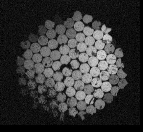
Figure 1a. Image of room-temperature end of sapphire fiber bundle.
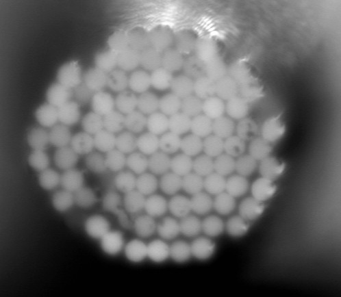
Figure 1b. Image of high-temperature end of sapphire fiber bundle.
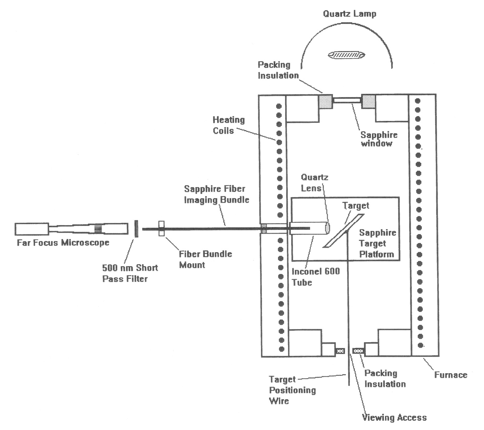
Figure 2. Schematic of high-temperature fiber optic imaging test apparatus.
justify a manufacturing system that would provide relatively cheap fiber. It should be noted that the normal specifications of fibers are as communications fibers, which can and have been greatly relaxed for use as an imaging fiber. The minimum useful pixel array to verify imaging is approximately 10 by 10, since the image size must be at least an order of magnitude larger than a single pixel to be able to form an image from pixels. The total length of fiber available for this program was about 20 m, leading to an individual fiber length of 20 cm. This is more than enough length to travel across the thermal barrier in a small furnace where the temperature varies from ambient to over 1000°C. The camera can be kept at room temperature using an air-cooled metal barrier between it and the furnace.
Unclad sapphire fibers were used. Cladding is used to prevent light losses and separate the fiber from environmental effects. In the present case, air is an effective cladding, fiber contact losses and crosstalk have been shown to be negligible, and environmental sealing can be done by sealing the outside of the bundle. The primary reason unclad fibers are not practical in common applications are that the light intensity in each fiber is very low and the fibers are long, so small losses are not tolerable. Also glass fibers degrade over time if unclad; this is much less important for sapphire. For high-temperature imaging the light levels must be high, so small light losses are unimportant.
A simple biconvex lens made of Herasil with a 5-mm diameter and 5-mm focal length focused the target onto the fiber bundle. Using the high-temperature adhesive the quartz lens was cemented into a Inconel 600 tube (2-cm. long, 1-cm diameter) at one end. A plug of alumina casting compound was put in the other end of the tube, and a hole was put into the plug somewhat larger than the fiber optic bundle to center it in the field of view of the tens. The Inconel tube was cemented onto a piece of sapphire scrap to keep it oriented properly, this small sapphire plate was cemented onto a similar plate as a height shim, and then the assembly was cemented on a 3-cm-wide, 6-cm-long sapphire plate that acted as a high-temperature optics table. A ceramic target with nickel-chromium evaporated high-resolution graphics was obtained from Metrigraphics. This target survived adequately at 1000°C. The resolution target was also cemented onto another sapphire plate that acted as a base, and a kanthal wire was cemented onto the back to be able to manipulate the position of the target on the sapphire optics table in the operating furnace. The vertical spacing of the lens tube was set to align it with the Comm hole through the side wall of the furnace. The fiber bundle was mounted through a hole support outside the furnace.
A Far Focus Microscope (Infinity Model K3, Boulder, Colorado) coupled to a black-and-white video camera (COHU, San Diego, California) was focused on the end of the fiber bundle through a Corion 500-nm short-pass filter. A COHU Model 1100 board-level CCD camera was also bought to perform the image detection. This camera has standard video resolution but was specialty adapted for direct contact of the fiber bundle on the CCD surface. The window on the standard CCD sensor (Sony) was removed and made interchangeable. The output of the cameras is in the standard RS-170 video format that can be recorded by a VCR or its video images grabbed, digitized, and processed by the imaging apparatus (Matrox, Quebec, Canada).
Hot-Zone Apparatus
A small cylinder furnace (Thermcraft) was used to provide the hot zone. The heater has an internal dimension 15-cm long and 7.5 cm in diameter and is rated at 1100°C and controlled for variable temperature with a 10-A Variac. The furnace uses iron-chrome-aluminum wire helically wound and embedded into a vacuum-formed ceramic fiber. The heater has 7.6-cm-thick vestibules on each end that have a 5.1-cm-diameter aperture that is blocked with ceramic fiber paper using a standard Typecast thermocouple inserted through one radial hole for temperature measurement during tests. The heater was made with two 0.95-cm-diameter radial access holes separated by 90°, both at the midpoint of the heater. The furnace ends were plugged with ceramic fiber paper alumina fiber blocks; sapphire support plates and ceramic putty were used as supports.
On one end of the furnace strips of alumina felt were wrapped around a 25-mm-diameter sapphire window, filling the aperture. A 50-W high-intensity halogen lamp provided the illumination on the target. The other end of the furnace was mostly filled with felt insulation except for a small slit to allow for observation of the movement of the target during imaging experiments. The video output of the far focus microscope was either fed into a VCR or directly to the PC imaging board for image acquisition.
Procedures
The arrangement of the apparatus in Figure 2 was a result of a number of iterative experiments and procedures. The basic procedure for the feasibility experiment was to align and focus the target and lens system by eye from the outside using the external mounting hole and the hole in the ceramic plug as sight holes. The fiber bundle was then threaded through the holes. The inner end of the fiber was placed at the focus of the lens by pushing it up against the lens, then moving it out by 9 mm. Since the focal length of the lens was 5 mm, a displacement of the fiber bundle end of 10 mm from the center of the lens (2-mm thick) and a placement of the target also 10 mm from the lens center would result in a 1:1 magnification image of the target onto the fiber bundle. The target was placed at an angle of 45° to the imaging axis to reflect from the lamp at the end of the furnace. The target was then moved toward, away, and across from the lens to reach optimal focus. The furnace was then heated to slightly over 1000°C and imaging experiments were performed.
Initially contact imaging video was to be used by cementing the fiber bundles (glass and sapphire) into the CCD window so that the bundles would butt up against the CCD. Ibis would be a very sensitive system and would not sacrifice resolution because the CCD pixels are 8-μm wide; small compared with the 100-μm fibers. This setup worked fine outside the furnace but not in the furnace. The CCD was too sensitive; even with the gain turned to a minimum the CCD was light saturated. Because there was no room to insert a short-pass filter to exclude thermal radiation from the furnace, illumination could only be done by adding more light from an external source and lowering the gain on the image sensor. Since this was not possible, the far-focus microscope and short-pass filter were used to sense primarily the illumination light in further experiments.
It was also initially thought that the best way to arrange the optics was to preset them for best focus, heat up the furnace, and record the best image. This was not practical because heating the environment moved the objects enough to change the focus, and contrast could not be maintained at high temperature because of thermal radiation noise. Initial tests showed it was not obvious that any image was present at all. Part of this problem was a result of the low resolution of the 97 fiber bundle, which in the case of contrast means that edges are always gray because the fibers are large enough to capture black from an edge and white from the area near the edge, averaging them at the other end to make the detected fiber gray. Noisy video images with low contrast are difficult to detect. Another part of the problem was that the bundle end (and thus its image) was significantly degraded by the preparation process for contact imaging. To achieve a totally flat end, the bundle was briefly ground on a diamond wheel. Whereas this worked well on the glass fiber bundle, it did not work on the sapphire bundle. The sapphire fibers lost most of their polish, and many of the fibers on the periphery fractured axially, leaving only partial fiber ends.
Initial experiments were done with this poorly polished bundle end, and it was very difficult to discern the presence of an image with a fixed target. If the target was moved, however, the movement of the light and dark areas across the bundle were very obvious in the video image. Part of the difficulty of detecting an image was caused by the video signal itself-there is noise in the system that further masks a fixed image of poor contrast. Moving the image allows the video noise to be averaged out so that the image is much more easily detected. As a result, the imaging system was modified to be able to move the target in the furnace to find the best focus and the clearest image through the bundle. After the preliminary experiments were conducted and some initial results obtained, the sapphire fiber bundle end was repolished using a 1-μm grit diamond paper. This polished the fibers properly except for a few blemishes and some of the fibers on one edge of the bundle.
The furnace was tested to calibrate internal temperatures with variac settings; a setting of 90% voltage results in a central temperature of slightly over 1000°C with both of the furnace ends plugged. This temperature could be reached in as little as 30 minutes but was usually increased gradually in an hour or more.
Experimental Results and Discussion
Sapphire Fiber Thermal Testing
A crucial feasibility experiment was performed to test thermally sapphire fibers at the beginning of the program. A fiber was inserted into the 1000°C environment of the furnace to test its physical integrity. It was inserted multiple times for periods between 1 see and 10 see at various depths. No change was observed in the fiber. The fibers were thus shown to be able to survive the 1000°C environment, the large temperature gradients associated with the furnace wall penetration, and the thermal cycling associated with furnace operation or fiber insertion. Although the sapphire fibers were expected to be very robust at 1000°C based on the generic properties of sapphire, a number of mechanisms could be proposed that might cause the fiber to fracture under thermal stress such that the fiber might simply break off during insertion into the furnace. This does not occur. Temperature gradients in the fiber optics are strictly axial as a result of the small diameter of the fibers. This implies that thermal stresses are negligible, since the scale on which they occur is that of the diameter of the fiber; the high thermal conductivity of sapphire will equalize the temperature across the fiber. The strength of a fiber is also higher than the bulk material because the diameter of the fiber is of the same order of size as the flaws usually responsible for the failure of larger pieces.
Room- Temperature Image Tests
Extensive room-temperature testing of the fiber bundles was done to explore imaging properties of the bundles and to determine how images of the high-temperature target would appear. The glass fiber bundle was used as a reference case for a perfectly packed bundle.
Figures 3a, b show images of a line using the glass fiber bundle. Figure 3a shows a contact image of a fat line where the sides of the line only half fill a line of fibers, causing the edges to appear as two vertical lines of gray. Although in these tests the cause for the grayness is known to be the misalignment of the edges of the fibers with the edge of a sharp image line, the image at the end of the fiber is indistinguishable from an out-of-focus image formed by a lens and properly illustrates the focusing problem in the system. Figure 3b shows an image of the same line that has been formed by imaging the line on the end of the bundle using the 5-mm-diameter quartz lens with light entering the sides of the fiber bundle.
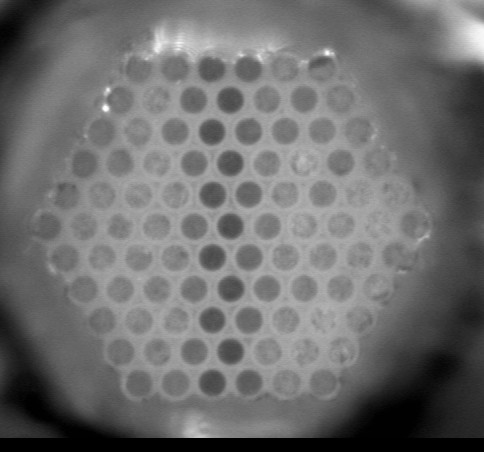
Figure 3a. Glass fiber bundle imaging of contact line image where edges half fill fibers.
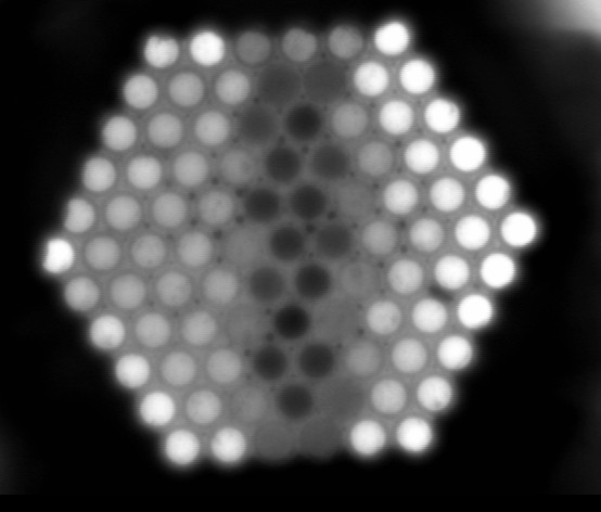
Figure 3b. Glass fiber bundle imaging of focused line image with light in the sides of the bundle.
Figure 4a shows an image of a line (on paper) in contact with what will be the hot end of the sapphire bundle where the room temperature end is in contact with the CCD detector. These images were taken before repolishing the room-temperature end of the bundle. The upper left part of the bundle is out-of-focus because of poor contact with the CCD plane. Figure 4b shows the same line that has been focused on the end of the bundle with the lens to be used for high-temperature testing. The focused line appears gray as a result of stray light captured by the fibers. The light halo around the bundle is another result of the stray light.
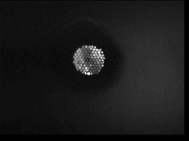
Figure 4a. Contact image of a line through poorly polished end of the sapphire bundle
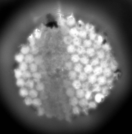
Figure 4b. Contact image focused line image through sapphire bundle.
High- Temperature Image Testing
The apparatus shown in Figure 2 was used in an experimental feasibility demonstration of fiber optic operation at temperatures over 1000°C. The high temperature is important as a result of changes in materials properties at high temperatures and as a result of the large temperature gradients necessarily created. Although the shortness of the sapphire fibers might be expected to cause too much heat transfer to the camera, metal shields and air fans permitted essentially room-temperature operation within a few centimeters of the outside of the furnace, whereas the fiber bundle protruded 13 cm from the furnace.
The first tests at high temperature were devoted to determining whether the high-temperature adhesive used to bundle the sapphire fibers would function adequately. A set of flat touching fibers was formed by hand and dipped in the adhesive, and then the adhesive was sanded off of the fiber ends before oven curing. The test bundle was then inserted multiple times into the furnace at 1000°C without degradation, proving that it would function well to bundle the fibers.
The basic problem with imaging systems at high temperature is that all of the hot objects in the scene are radiators. Normal visual images are formed as results of intensity differences in the light reflected from different objects. Usually the light source comes from one direction, which creates intensity shading and shadows caused by three-dimensional variations in the shape of the object that are used as cues to understand more about the scene. At 1000°C, illumination comes from all angles (the furnace walls) and the object itself is usually radiating, causing images that are confusing to interpret. The most common solution to this problem is to provide a special light source that is sensed at the same time that thermal radiation
is excluded. This can be done using laser illumination and line filtering, or LIV illumination and low-pass filtering. For the purposes of imaging experiments, another practical method might be to put a patterned mask of lower emissivity material at the front of the fiber bundle. Here laser illumination was tested, but the scale of the laser speckle prevented imaging of the very small images necessary for this experiment. Other difficulties of high-temperature imaging include plating of optics and oxidation/corrosion that increases emissivity of objects. Experiments demonstrated that a 500-nm short-pass filter was sufficient to screen out thermal radiation at 1000°C. Without filtering the image began washing out at 725°C and was totally gone by about 800°C. A 650-nm short-pass filter reestablished the image at 850°C but was ineffective at 1000°C.
Thermal radiation is defined quantitatively by the Planck function as it describes blackbody radiations body that absorbs all incoming radiation. The total radiated power by a blackbody at temperature T is given by the Stefan-Boltzmann function, where Wtotal (T) = 5.679 X 10⁻¹² T4 W/cm2; the T4 dependence of the radiated power accounts for the dominance of radiation at high temperatures. When comparing illumination radiation with thermal radiation, although total radiant power increases as T4 , the wavelength of maximum emission moves toward a shorter wavelength, and within a specific wavelength band total emission may increase in proportion to T2 or T3. For real materials the total radiated power differs from that of a blackbody by a fraction defined as the total emittance, εt. Total emittances are integrals over wavelength of detailed emissivities that are also wavelength-dependent and are often quite different at infrared wavelengths compared with that measured at visible wavelengths. Total emittances can be quite low but can depend strongly on temperature, usually increasing with temperature. Most metals also oxidize or form nitrides at high temperature in air, a process that greatly increases their emissivities.
Figure 5 shows a far-focus microscope image of the cool end of the sapphire fiber bundle where the hot end is in the furnace at a temperature over 1000°C. The close packing of the fibers can be seen, as can the poorly polished fibers at the lower left and the fractured fibers around the periphery. Although the fighting in the furnace is intended to be uniform, it is not because the object imaged on the bundle end is the white portion of the ceramic target, tilted at 45° to the imaging axis causing less intensity on the left of the image. It is not known whether the fact that many of the peripheral fibers are darker is a fundamental phenomenon.
The target was then moved to achieve a best focus (along the imaging axis) of a dark edge placed vertically across the image, as shown in Figure 6. The contrast is not high; other tests showed this to be a result of the environment rather than a characteristic of the video imaging/fiber optic system. At high temperatures the emissivities of almost all materials increase, which means that their reflectivities decrease and that the general visibility of objects under external illumination in a field of view have decreased significantly. Two repeat images were taken, together with two black background images. Both these pairs were averaged separately to reduce noise and the background average subtracted from the edge image with the result shown in Figure 6. The target steadily degraded at temperature, so that some of the fine edges
were lost. This appeared to be mostly some sort of chemical reaction, because the plated image disappeared entirely from the bottom 3 mm of the target but remained intact at the top. As received the target was black and white, whereas after the first excursion to 1000°C the pattern became green. To try to capture a line across the bundle, a chrome wire was inserted into the field of view. The wire was 0.38 mm in diameter and provided a black image if it was inserted at the lens focus while it was still cold. This was possible but difficult because the wire had to be moved to the focus as indicated on the live video of the fiber bundle, held steady to a fraction of a millimeter, and then the image captured by the computer. The wire was flattened with a hammer to reduce further its thickness compared with the approximately 1.6-mm sapphire fiber bundle. Many attempts resulted in some excellent line images filling about half the diameter of the bundle image but by the time an image was captured, the contrast was significantly reduced as the wire heated up. Figure 7 shows a processed (averaged and background subtracted) image of the wire passing through the image from left to right at the center of the image. It was clear from watching the imaging live (and from video) that as the target was moved, small details of the pattern on the target were seen to move across the fibers. Unfortunately, the low contrast and the poor resolution of the bundle prevented the pattern from being recognized in still video images.
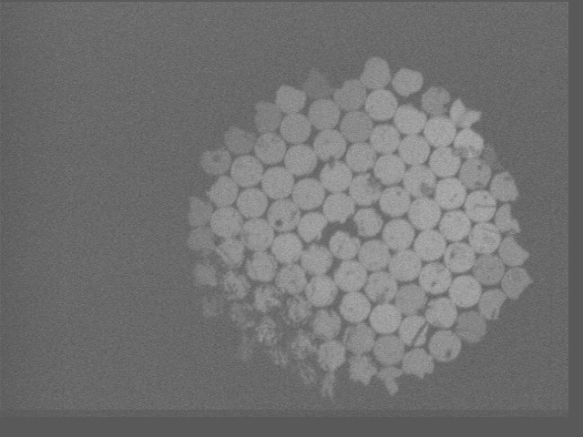
Figure 5. Image of the room-temperature end of the sapphire fiber bundle during feasibility experiments at 1000°C.
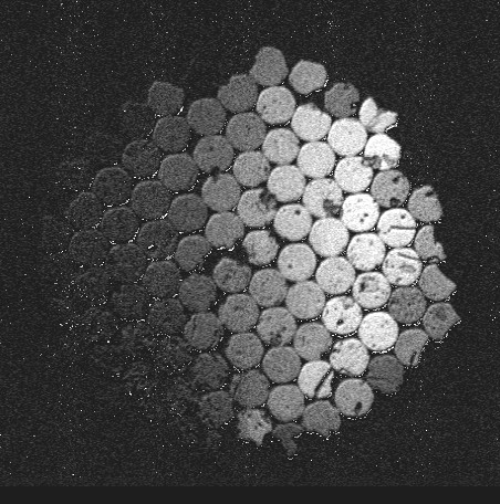
Figure 6. Image of an edge across the image through the sapphire bundle during feasibility experiments at 1000°C after averaging and background image subtraction.
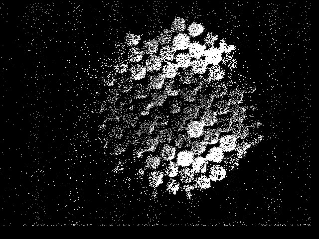
Figure 7. Image of a dark line through the sapphire fiber bundle during feasibility experiments at 1000°C after averaging, background image subtraction and intensity level processing.
Conclusion
Sapphire fiber optic imaging at temperatures over 1000°C has been shown to be feasible. The sapphire fibers were grown using the LPHG method. A low-resolution (100 fiber) high-quality sapphire fiber imaging bundle was assembled. Closepacked bundling of short fibers was achieved. Although fiber cladding techniques are still not adequate at high temperatures, promising avenues do exist for solving this problem, and unclad fibers may be usable as they were in the successful experiments described above. Imaging of scenes at temperatures over 1000°C was done using standard video imaging equipment, but image contrast was shown to be degraded from that at room temperature, and short-pass filtering was required to remove thermal radiation noise.
The economics of sapphire fiber production currently prevent fabrication of high-resolution imaging bundles, but it is believed that a commercially viable high-temperature imaging product can be manufactured. Experiments demonstrated that high-quality sapphire fibers withstand the thermal gradients and thermal cycling and that smaller sapphire fibers can be fabricated for higher resolution imaging, whereas drawing methods for making quartz fibers prevent their manufacture in diameters of a few microns. The basic applications of high-temperature imaging are for nonintrusive inspection and control of equipment and processes as well as research and development. Specific examples of equipment of interest include turbomachinery, combustors, and furnace processing.
Acknowledgements: The authors gratefully acknowledge the support of this work by the National Aeronautics and Space Administration under Contract No. NAS3-27568. Address correspondence to Stephen C. Bates, Thoughtventions Unlimited, P.O. Box Glastonbury, Ct 06033, USA. E-mail: thought@Thoughtventions.com
Published in Fiber and Integrated Optics, 16, 4, pp 387-405 (1997)
References
1. Schempp, W. V. 1994. Fiber optic imaging: An introduction. SC32 Short Course Notes, SPIE, OE/LASE '94, January 22-29, Los Angeles, CA.
2. Fejer, M. M., G. A. Magel, and R. L. Byer. 1984. Laser-heated miniature growth apparatus for single-crystal optical fibers. Rev. Sci. Instrum. 55:1791.
3. Merberg, G. N., and J. A. Harrington. 1993. Optical and mechanical properties of single-crystal sapphire optical fibers. AppL Opt 32:3201-3209.
4. Chang, R. S. F. 1993. Development of high optical quality high temperature sapphire fibers. Final Technical Report, NASA Contract #NAS1-19508.
5. Jundt, D. H., M. M. Fejer, and R. L. Byer. 1989. Characterization of single-crystal sapphire fibers for optical power delivery systems. AppL Phys. Lett. 55:2170-2172.
6. Gloge, D. 1972. Bell Syst. Tech. J. 51:1767.
7. Phomsakha, V., R. S. F. Chang, and N. Djeu. 1994. A novel implementation of laser heated pedestal growth for the rapid drawing of sapphire fibers. Rev. ScL Instrum. 65:3860.
8. Phillipp, W. H., L. C. Veitch, and M. H. Jaskowiak. 1994. Guanidine soaps as vehicles for coating ceramic fibers. NASA Tech Briefs.