High Altitude UAV Droplet Heat Exchanger
40 Nutmeg Lane
Glastonbury, CT 06033
Abstract
An investigation of the overall feasibility of a low-mass droplet heat exchanger (DHX) for a UAV is described. The proper amount of heat can be transferred at high altitude, the device is technically feasible as an engineering device, and the mass of the DHX is much less than that of a comparable state of the art tube and fin heat exchanger. The performance increase achieved for the UAV is worth the investment to develop this new application for droplet heat exchangers. The droplet material, size, speed, mass loading, duct area, and duct length for the heat exchanger was defined to obtain the heat rejection needed for a typical UAV engine at altitude. The operation of the conceptual device was defined and its range of operation explored. A droplet spray and collector system to generate and capture the droplet field was defined. A DHX can tolerate a UAV flight envelope, including speed and attitude changes and adverse atmospheric conditions.
EXECUTIVE SUMMARY
Unmanned aerial vehicles (UAVs) are now being used as atmospheric sampling devices, but significant advances in performance must be achieved for extended sustained flight at altitudes up to 30 km. Unmanned aerial vehicles (UAVs) currently use traditional circulating glycol/water heat exchangers to cool their engines. In these systems the radiator that transfers waste heat from the engine to the surrounding air relies on forcing air through a closely spaced mesh of cooling fins that are heated by the circulating cooling liquid. The finned metal heat exchanger must be large and massive to achieve the desired cooling. Furthermore, at maximum altitude heat transfer is greatly reduced because of the low air density. The forced air flow through long and narrow restrictions also induce a significant overall drag on the aircraft. The added mass and drag together reduces range, flying time, or payload of the aircraft. A means for increasing heat transfer at high altitude is needed, together with decreased weight and aerodynamic drag of the heat exchanger.
The standard metal finned heat exchanger can be replaced by a droplet heat exchanger (DHX), where a circulating liquid is sprayed to create a dense (0.1 -1 volume %) droplet field in a ducted airstream to directly transfer engine heat from the cooling liquid reservoir to the air. A droplet heat exchanger has a much higher thermal contact area, lower pressure drop, and greater heat exchange dynamic range providing enhanced heat transfer at high altitude. Use of a droplet heat exchanger will greatly reduce total radiator weight and significantly reduce overall aircraft weight, increasing achievable altitude, heat exchanger performance, and time of flight for a given payload. The drag of the heat exchanger will also be reduced because a smaller frontal area will be needed and the large pressure drop of the radiator fins is eliminated. Flow velocities in the tens of m/sec that are typical to UAVs permit inertial capture of droplets over 100 microns in diameter, well within the size range required for efficient heat transfer. The DHX will tolerate particles in the atmosphere as well as vehicle speed and attitude changes.
Spray heat exchangers have already been extensively investigated and proven feasible in other applications, both experimentally and theoretically. Droplet heat exchanger experiments have demonstrated multi-100 kw heat rejection with much lower flow volumes than available for a UAV, indicating that the weight and drag savings already demonstrated for similar systems can be applied to UAV design. Redesign to make the system applicable to a UAV and tolerant to vehicle motion and environmental conditions will lead to a heat exchanger that is far superior to conventional systems in heat transfer and weight with lower drag in addition. Success of a spray heat exchanger for a UAV could lead to many other important military and commercial applications.
Results Summary. Research results consist of the detailed design of a Droplet Heat Exchanger for a high altitude UAV, a comparison of this design with current state of the art heat exchanger technology, an assessment of the feasibility of the feasibility of the DHX based on its advantages and its practicality.
Achievements of the program are summarized as follows:
1) Design procedures for a high altitude DHX were developed.
The process of heat exchange for a DHX takes place between a volume field of uniformly sized droplets and a gas flow passing through them. The droplets are aerodynamically large, so that the gas flow direction can be independent of the liquid flow direction. The design of a typical DHX begins with the need to transfer a specific heat load. The gas and liquid flows are then defined to accomplish this heat transfer, where the heat transferred from the droplet field is determined by its mass flow and the temperature difference of the droplets between injection and collection. The droplet volume loading is determined by matching the heat capacity of the flowing droplets with that of the flowing gas. The total heat transfer is then set by sizing the gas and droplet inlet areas. Other parameters of the DHX such as heat transfer rate, flow geometry, or total temperature drop, are determined by the droplet size, droplet velocity, and duct length. The overall design process is complex; high altitude design for low mass places unusual constraints on DHX design.
2) The detailed operating parameters of a state of the art tube and fin heat exchanger were obtained for direct comparison with the DHX design.
Baseline parameters for UAV tube and fin heat exchanger design were established by data supplied by Dave Bents of NASA Lewis. This data is derived from current work by ERAST to define a 24 km altitude atmospheric sampling demonstrator vehicle. The design of this UAV provides the engine heat loads and the state of the art tube and fin heat exchanger parameters (including mass) for these heat loads.
3) Design parameters for a 100 kW 24 km altitude Droplet Heat Exchanger (DHX) were established.
A 100 kW DHX operating at 24 km was designed with a droplet mass flow of approximately 1.5 kg/s, inlet temperature 100°C, 10 m/s injection velocity of 200 (m diameter droplets, gas intake area 0.5 m x 1.0 m, 1.5 m long. The DHX uses DOW 705 silicone high vacuum oil.
4) The engineering details of this design were specified.
The geometry of the DHX was specified and FLUENT computations performed to examine the details of the flow and heat transfer. The injector and collector design was specified and components were designed for minimum mass. The components of the overall system were specified to the extent of their influence on the overall mass of the system.
5) The mass of the prototype was compared with the current state of the art.
The mass of the components of the designed DHX system were estimated relative to the baseline parameters for UAV tube and fin heat exchanger system. Comparing component masses indicates an overall estimated mass savings of a significant fraction of the 10 - 20 kg total mass of the tube and fin heat exchanger system with a similar heat rejection capacity.
6) An overall positive assessment of a UAV DHX was described.
A DHX is very well suited to the particular application of a heat exchanger for a high altitude UAV because: 1) direct heat transfer from the fluid to the air allows more of the limited heat capacity of the air to be used (larger (T's), 2) Total DHX mass is much less because a) 10 m/s droplet velocities and 1.5 m flow pathlength allow relatively large mass flow rates but low total droplet mass, and b) light, low thermal conductivity materials can be used that result in a low structural mass compared with standard radiators, 3) the DHX has low drag, 4) negligible fluid losses occur for a typical UAV flight time, and 5) the required UAV engine heat rejection power is appropriate for currently established (both experimental and theoretical) DHX technology and the associated droplet field parameters are in the center of a typical DHX operating envelope.
Major design problems were solved:
1) Fluid Loss: Droplet loss is eliminated by: a) Minimizing small droplet production through proper jet excitation frequencies, b) Using a cross flow intake geometry that captures small droplets in the intake recirculation zone, and c) using local cusps to capture surface films and surface droplets. Fluid loss to evaporation has been shown to be insignificant because the fluid exiting the DHX is cool and any fluid evaporated at higher temperatures upstream in the DHX has recondensed on the droplets.
2) A combined cross-flow/co-flow design allowed a compact injector and droplet field to exchange heat with a much larger area gas flow.
Based on this work the feasibility of a high altitude UAV DHX has been demonstrated.
BACKGROUND
The background for this proposal is in the areas of 1) Droplet Heat Exchangers, and 2) UAVs.
Droplet Heat Exchangers - Conceptually, a droplet heat exchanger is just a way to directly transfer heat between a heat transfer fluid that is cooling some heat source and an external gaseous atmosphere. By spraying a relatively dense field of heated droplets into a lower temperature airstream that moves past the droplets, heat is exchanged by conduction and convection between the liquid and the gas. Evaporation is minimal if the liquid is kept at a temperature well below its boiling point. Heat transfer is very efficient because of the very large total contact area, typically 100-500 µ m diameter droplets. The technical challenge is to create, maintain, and collect the droplets.
For a specified thermal power rating, the size and performance of a droplet heat exchanger are determined primarily by 1) The density and composition of the gas, 2) The temperature drops across the two media, 3) The initial temperature difference between the two media, 4) The relative mass flow rates of the two media, 5) The diameter, density, and specific heat of the droplets, 6) The droplet injection velocity, 7) The gas inlet velocity, 8) The cross-sectional area and length of the heat exchange region. Computer modeling is already available to calculate the full problem, given external design constraints.
Previous DHX applications have been mainly to space power systems [1-4] and high temperature heat exchanger systems [5], but considerable work has also been done on spray heat exchangers in air. This research has shown that droplets are an effective and efficient technique for transferring heat from a liquid reservoir to a surrounding gas or even into the vacuum of space.
Droplet heat exchangers are a subset of a broader class of devices known as Direct Contact Heat Exchangers (DCHX's) [e.g. [6]]. These devices achieve increased efficiency by minimizing the number of heat transfer interfaces, moving the heat transfer medium through the heat sink environment. Most solid-liquid, solid-gas and liquid-gas heat transfer can be done in this way, usually adding cost and complexity in exchange for increased efficiency. Often large gains can be made in the compactness of the heat exchanger also. Other major advantages of DCHX's are greater capabilities at high temperatures and reduction of corrosion and fouling problems.
A schematic of a large-scale droplet heat exchanger is shown in Figure 1. The droplet field is shown as dotted, whereas the flow streamlines are shown in one section as lines. The cross-hatched section shows liquid reservoirs under pressure to supply the sprays. Droplet heat exchangers take many forms, depending on the flow configuration and the mechanism for droplet movement. Major flow configurations are linear (e.g. Fig. 1), and radial, where the droplets may be co- or counter-flowing. Droplet motion can be caused by injected inertia, flow drag, gravity, or electromagnetic forces.
Experiments have proven the gains in efficiency at designed heat rejection power levels and experimentally verified extensive computational modeling for a variety of droplet heat exchangers. The devices have shown that there can be negligible mass loss over long periods even in high flow rate exchangers. Problems of mass loss through a variety of mechanisms (droplet instability, turbulence, etc.) and contamination of the liquid have been addressed.
UAVs - The specific UAVs of interest are light, high altitude, high lift, large wing span, relatively low engine power aircraft. Flights will be long and speeds low.
The two primary science mission requirements for advanced RPAs are: 1) very high altitude (up to 30km), long duration (up to 50 hours) with science payloads of 100-1400 kg, and 2) high altitude (24km), long endurance (96 hours) with 50-1600 kg payload capability. Both missions require aircraft that would fly at these altitudes at subsonic speeds in order to meet key science measurement requirements.
Application of DHXs to UAVs. Current applications of droplet heat exchangers have been to stationary systems or space vehicles that are particularly sensitive to droplet heat exchanger gains - efficiency, high temperature, or compactness. Higher efficiency and lower weight are major advantages in a UAV application but so is the potential to perform heat exchange at high altitude. The larger thermal contact area of the droplets in the flow compared to a solid radiator, and the ease of increasing duct area and droplet injection allows heat exchange to be greatly increased with altitude.
Application to UAVs involves somewhat different constraints than those encountered in current droplet heat exchangers. Both flow and heat rejection rates are externally imposed by the specific and variable operating condition of the aircraft. At a particular flow rate the heat rejection requirement can also be quite variable; the most demanding condition is at maximum altitude where the air density has decreased by a factor of 100 compared with sea level conditions. Flow speeds are usually high (relative to current droplet heat exchanger design), usually 10-100 m/sec. The droplet field flow (but not the air flow) inside the heat exchanger duct will also change to some extent when the aircraft changes direction of the aircraft relative to the surrounding air.
INTRODUCTION
The overall objective of this work was to demonstrate the feasibility of a droplet heat exchanger for a UAV. Work was done in four major areas. The first area of work was modeling to demonstrate the feasibility of creating a spray and flow configuration that would result in the appropriate amount of heat transfer. The second area was the demonstration that such sprays can be generated and captured in an air stream consistent with a UAV design. The third area was the demonstration of the existence of specific enabling engineering technology for a droplet heat exchanger. The fourth area was the analysis that showed that the spray heat exchanger could be designed to operate properly under vehicle speed and attitude changes as well as adverse atmospheric conditions such as rain and dust. Previous work was adapted and extended to provide some solutions. Adequate experimental work has already been done to prove the concept; it was only necessary to demonstrate the design parameters and devices.
HEAT TRANSFER DESIGN
This work starts from an analysis of UAV heat rejection needs and the extensive droplet heat exchanger background work previously done. First the target parameters for heat exchange at high altitude are defines. Droplet heat exchanger basics are then discussed to introduce and motivate this unconventional technique for heat exchange. DHX design methodology is then discussed in general and for the specific case of a high altitude UAV. Finally the specific DHX design is described, together with computational fluid mechanics prediction of the flows and heat exchange.
Design Goals: The overall design goal of the entire program is to specify a DHX for a high altitude UAV. The primary motivation is to significantly reduce heat exchanger mass from current state of the art heat exchanger technology, enabling improved aircraft performance in the form of for instance higher altitude for an otherwise unmodified aircraft. The program is specifically aimed at the technology embodied in the NASA ERAST program that attempts to create unmanned, subsonic aircraft for atmospheric sampling at 70,000 ft altitudes and higher carrying a 1000 lb payload. These aircraft are light, high altitude, high lift, large wing span, and have relatively low engine power. Flights are long and speeds relatively slow. It is proposed to replace state of the art tube and fin heat exchangers [8], [9] currently planned for such a vehicle with a DHX.
Specifying a baseline for comparison of this technology with a DHX has been greatly eased by the definition of an ERAST demonstrator vehicle. Target engine power was approximately 100 kW, target vehicle speeds (and thus gas velocity through the DHX) was in the range of 50 - 100 m/s, and the target altitude was assumed to be 24 km.
Table 1. Tube and fin radiator parameters for ERAST demonstrator.
Rotax 912 engine:..................................Heat Power(BTU/s)
80 hp....................1. radiator...........................85.4
80 kft...................2. oil cooler.......................17.2
3 stage.................3. intercooler (28)................. 4.9
..............................4. 2nd stage.......................12.4
..............................5. aftercooler.....................12.5
Tube and Fin Radiator Parameters:
Size:(Square - ft x ft)..................Air Mass Flow(lbs/s)............Radiator Mass (with fluid)(lb)
1. 3 1/2...............................................4.9..............................................15.4
2. 1.7..................................................0.8...............................................7.3
3. 1.5..................................................0.13..............................................7.6
4. 1.75.................................................0.35..............................................8.25
5. 1.98.................................................0.18..............................................7.6
Heat Exchange at High Altitude. Engine power and heat rejection requirements are normally a maximum at takeoff for a subsonic aircraft. At high altitude the air density is so low that its heat capacity has fallen dramatically. Thus, a major design characteristic of a high altitude heat exchanger is the air itself. At 25 km, although the temperature has dropped to - 49°C (aiding heat exchange) air density is only 4 % of its sea level value. The next generation of atmospheric sampling aircraft will have a target altitude of 38 km, where the temperature has increased to -24°C and the density has decreased by almost an additional factor of 8. When the density of air is small, it has little heat capacity and can only carry away heat in large volumes that require very large area heat exchangers. For instance, for a temperature rise of 50°C and a square duct 0.5 m on a side, the heat power carried away by a 60 m/s airstream is only 70 kW. At 38 km, this power is reduced to 8 kw. Typical engines currently require 100 kW of heat rejection.
Figure 1 shows the heat capacity of air per square meter frontal area at a speed of 60 m/s for a standard atmosphere assuming a 50°C temperature increase in the airstream. If the coolant is water/glycol at 100°C and the liquid/gas temperature difference is 150°C, a 50°C gas temperature rise is possible but not easy to achieve for a tube and fin radiator coolant temperature drops. Associated with the need to exchange heat with large volumes of air is the structure needed to capture the cool air, transport it through the heat exchanger, and reject the warm air back into the atmosphere.
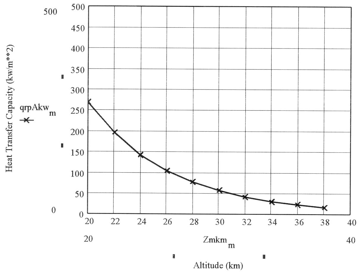
Figure 1. Heat transfer capacity of high altitude air.
Droplet Heat Transfer Basics: The basic concept of a DHX is to transfer heat from a hot liquid to a cold gas by injecting droplets of the liquid into the gas stream, allowing them to cool, and then collecting them inertially as the flow is turned and the droplet and gas trajectories diverge. Heat transfer is not intended to be by evaporation, but by conduction within each drop and convection in the airstream as it flows around the drop. The advantage of this type of heat transfer is that the heat transfer between the liquid and the gas is direct without an intermediate material interface that would interpose its own thermal conductivity and contact heat transfer coefficients to reduce heat transfer. By dispersing large numbers of droplets of fairly small size a large heat transfer area can be obtained. Proper choices of droplet size leads to stable droplets, and proper choice of droplet material allows recirculation of the liquid with minimal losses.
A schematic of a classical counter-flowing, gravity driven droplet heat exchanger of the type shown in Fig. 2. This design shows one technique for joining the spray and gas flows aerodynamically to minimize disturbances. It also uses the minor effects of gravity to enhance the droplet/gas velocity difference and simplifies collection by using a gravity pool. The gas stream is also buoyantly stable; the heated air tends to rise. This type of geometry has the advantage of a long path where the droplets and gas are exchanging heat, as compared with a cross-flow device, which provides a simpler injection and separation/collection geometry for the droplet, but relies on rapid heat transfer from drops to gas.
The parameters of a DHX include the gas and liquid properties, the droplet size, loading, and speed, and the overall geometry of the DHX. The important gas properties are its density, ρ g, temperature, Tg, specific heat, Cpg, thermal conductivity, kg, velocity, ug, and the dimensions for the ducted flow. The important droplet parameters are the droplet diameter, dd, temperature, Td, and velocity, ug, the droplet volume fraction in the flow, β and the density, ρ l, and specific heat, Cpl, of the liquid. Less important properties include the viscosity of the gas and liquid, and the liquid thermal conductivity. Important dependent properties include the Reynolds number, Re, Nusselt number, Nu, Weber number, We, droplet drag coefficient, CD, droplet volume and frontal area, and the diameter and spacing of the injection orifices.
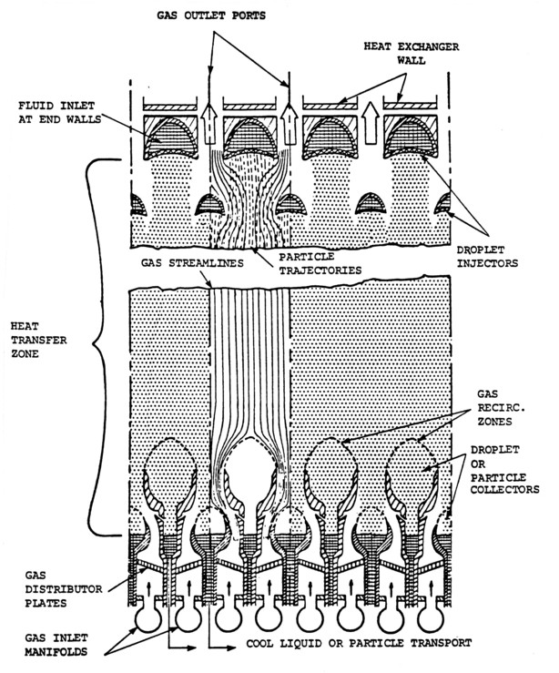
Figure 2. Schematic of a vertical, counterflowing DHX.
The gas flowing past the droplets is the lower temperature thermal reservoir to which heat is transferred. The gas can be co, cross, or counter-flowing with the droplet field, since the flow does not cause large changes in the droplet trajectory. The heat transfer capacity of the gas is determined by its density, its specific heat, and its temperature relative to the liquid in the droplets. The rate at which the gas can transfer heat is also determined by the mass of gas that flows past the droplets. For maximum heat transfer efficiency the heat capacities of the gas and liquid are relatively closely matched.
The heat rejection power, P, of the DHX assuming a droplet field area, volume fraction, speed and temperature loss by the liquid is
P = cplΔTl(dml/dt)
where Δ Tl is the temperature difference of the liquid, and the liquid mass flow, dml/dt, is
dml/dt = Aβ ρ lUl
where A is the area of the droplet field. Note the direct dependence of heat transfer power on mass flow, which is determined by the number of droplet orifices, their diameter, and the fluid injection speed. The heat power rejection capability is then
P = cplΔ TAβ ρ lUl
The mass flow of droplets is also determined by the total area of the droplet field, its mass fraction, and the density and velocity of the liquid drops. The other parameter determining the heat transferred between the liquid and gas is the temperature difference that is achieved between the inlet and exit of the DHX. The droplets cool as they pass through the airstream before they are collected and recirculated, while the gas is heated and flows back into the atmosphere. The temperature gradient for the liquid is [3]
dTl/dx = - (6Nukg/ρ lUlcpldl2)(Tl - Tg)
and the corresponding gradient in the gas is dTg/dx = - (6Nukgβ /ρ gUgcpgdl2)(Tl - Tg)
where Tl is the temperature of the liquid, Nu is the Nusselt #, kg the thermal conductivity of the gas, ρ l is the density of the liquid, Ul is the velocity of the liquid, cpl is the specific heat of the liquid, β is the volume fraction of droplets, and dl is the diameter of the liquid droplet. The Nusselt number in turn, is given by
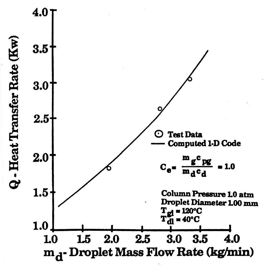
Figure 3. Heat power transferred vs. mass flow in an experimental DHX. [5]
Nu = 2 + 0.74Pr1/3Red1/2
where Pr is the Prandtl number (0.7 for air), and Re is the droplet Reynolds number, ρ gUldl/µ g.
MultikW experimental DHX's have been extensively documented in a wide variety of programs. Spray heat transfer has been studied extensively at the subcontractor STI Optronics [5] for flow parameters close to those expected to be encountered in UAV applications. Fig. 3 shows the global heat transfer rate versus the droplet mass flow rate. This figure indicates both the agreement of experiment with theory and that kilowatts of power can be exchanged in real devices at the flow rates described in this program.
Bruckner and Mattick [1] describe their experimental work on a 10 atm. high-temperature radial droplet heat exchanger that has gas velocities on the order of 10 m/sec, liquid mass flow of 3.8 kg/sec and a heat transfer rate of 268 kw. Shown in Table 1 are the characteristic parameters of a low temperature droplet heat exchanger used in a Brayton Cycle [3], and presented to illustrate the typical parameters of experimental droplet heat exchangers. This is a counter-flowing radial DHX shown schematically in Fig. 4, where the hot air enters at the outside and the cool droplets are sprayed in at the center, the reverse heat exchange process from that considered in this program. The air temperature variation is shown in Fig. 5; the gas cools as it moves inward, while it heats up the liquid droplets that are moving outward. The radial distance of the spray-flow interaction is only 5 cm. In the present case of a high altitude UAV DHX the reduced density is compensated by the much larger area.
Figure 4. Schematic of radial counterflow Droplet Heat Exchanger (4 droplet trajectories shown for clarity).
Table 2. Droplet heat exchanger parameters for a 100-kWe Brayton Cycle. [3]
Thermal power (kW) 163
Droplet Material --- Dow 705 oil
dm/dtgas (kg/s) = 1.9
dm/dtdrop (kg/s) = 1.82
Thermal capacitance ratio, Cs = 0.39
Effectiveness = 0.89
Droplet diameter (µm) = 300;
Droplet injection vel. (m/s) = 7
Droplet injection angle = + 45°
Gas inlet velocity (m/s) = 10.7
Gas pressure (atm) = 4.8
No. of gas inlet ports = 8
No. of droplet injection orifices = 10,660
Diam. of injector orifices (µ m)= 168
Central manifold diam. (mm)= 100
Height of chamber (mm)= 125
Diameter of chamber (mm)= 312
A major parameter of a heat exchanger is the effectiveness with which it transfers heat. More important for weight critical applications, such as UAV, is the mass specific effectiveness, defined as
Z = Q/[cpgΔ TinMhx]
where Cg is the specific heat of the gas, DTin is the temperature difference at the inlet of the heat exchanger, and Mhx is the mass of the heat exchanger. A plot of this mass specific effectiveness is shown in Fig. 6 [6]. From this plot it can be seen that as much as a factor of 10 in mass can be gained by using a droplet heat exchanger. The fundamental reason is that the elimination of the use of an intermediate metal heat exchanger between the coolant fluid and the cooling airstream. The conditions of the data in the figure are appropriate for the UAV application.
DHX Design Methodology. The concept of a DHX is simple: transfer heat directly from a field of uniformly sized droplets to an air stream passing through the droplet field.
The process of heat exchange takes place between a volume field of uniformly sized droplets and a gas flow passing through them. The droplets are aerodynamically large, so that the gas flow direction can be independent of the liquid flow direction. The high efficiency of heat transfer results from the large total surface area of the droplets and the fact that there is no intermediate material (such as a metal shell) that accounts for a significant part of the overall temperature difference between the gas and liquid heat reservoir media.
The design of a typical DHX begins with the need to transfer a specific heat load. The gas and liquid flows are then defined to accomplish this heat transfer. Usually the heat transfer process is enclosed to better recapture the liquid after it has transferred its heat to the gas. Merging the liquid and gas flows must be done carefully to avoid flow interactions in the region where the flows join and separate. Heat transfer symmetry and uniformity is often greatly changed by complex flow and channel interactions.
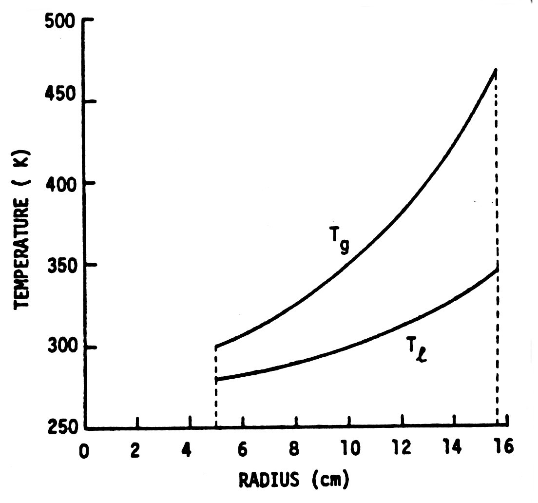
Figure 5. Temperature profiles of the DHX shown in Fig. 4 and specified in Table 1.
A DHX is described by the physical size of the droplet field, the parameters of the droplets, and the parameters of the gas. The overall heat exchanger is defined by the superposition of the droplet field and the flow field. The spatial characteristics of the droplet field are determined by the size and area distribution of orifices that supply the liquid flow and the distortion of the droplet field as it interacts with the gas flow field. The heat transferred from the droplet field is determined by its mass flow and the temperature difference of the droplets between injection and collection. The droplet heat transfer capacity is usually matched with the gas heat transfer capacity, which is scaled by changing its velocity and area to obtain a given heat flow.
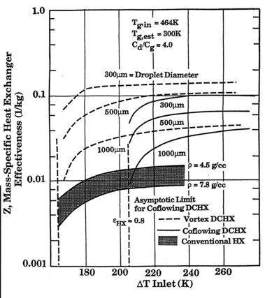
Figure 6. Mass specific heat exchanger effectiveness.
The droplet liquid is initially injected as a columnar jet at each orifice. At a distance of 1-10 orifice diameters downstream the liquid jet breaks up into droplets as a result of fundamental aerodynamic instability. This instability is controlled by oscillating momentum in the liquid jet itself such that a single droplet size results. The velocity of the droplets is the velocity of the liquid jet accelerated or decelerated by the drag of the surrounding gas. The total mass flow for heat transfer thus results from a combination of the droplet velocity, the droplet size, and the total number of orifices. The droplet loading, or mass per unit volume, is determined by the droplet size, the droplet velocity, and the number of orifices per unit area.
Many of these parameters have inherent limitations. If the droplets are too large and the velocity difference between them and the gas is sufficient, the droplets themselves become aerodynamically unstable, breaking up into smaller droplets. As the droplet size decreases, droplet acceleration increases and the droplet/gas velocity decreases, decreasing heat convection and heat transfer. If the droplets are too small they are swept into the flow and cannot be inertially separated from the flow and recirculated. Smaller droplets have greater heat transfer because for the same mass flow their total surface area is larger. A very small droplet field is difficult to create because large numbers of very small orifices (half the diameter of the droplets) are expensive to make. The number of orifices is limited by the need for supporting structure
between them (packing density) and the practical difficulty of making a very large number of high quality holes. Automated machining techniques have eased this latter difficulty greatly. An additional note about the droplet field is that whereas the field is injected as an ordered array, the position of the droplets is quickly randomized as a result of vortex wake forces of a preceding drop on a following drop. This randomization does not lead to collisions and agglomeration or breakup because aerodynamic forces of the overall flow field tend to keep the droplets separated.
The variability in the design of the droplet field occurs in changing the surface area to mass ratio, the total mass flow, the velocity relative to the gas stream, the number of droplets per unit area, and the initial temperature of the droplets.
For this program, the gas characteristics are fixed, as well as some of the liquid characteristics, so that the DHX design becomes an effort to match the droplet field to the gas field to optimize heat transfer to a gas that has very limited heat transfer capacity relative to the demands for heat rejection by the engine. The altitude and the flight speed of the aircraft specify all of the parameters of the gas flow, which determine the mass flow per unit area of gas. The flight velocity is set by the overall aircraft design and the need for subsonic gas sampling. It might also be noted that high altitude UAV's must be very light with relatively weak structures, which means that accelerations on the craft must be small compared with gravity - an ideal situation for a DHX. The heat exchange capacity is determined by the temperature of the air and the temperature of the coolant fluid - the droplet liquid. At high altitude the air temperature varies from - 50°C to -20°C depending on the altitude. The temperature of the coolant varies from boiling water temperature (around 100°C) to much higher temperatures for the supercharger oil.
The flight speed, altitude, and engine characteristics determine the mass flow of gas, the heat power needed to transfer, and the temperature difference between the two heat transfer media. For optimum heat transfer efficiency the mass flow of droplets is designed to roughly match the gas mass flow, and the droplet size and speed are set to assure that heat is efficiently transferred to the gas as the gas velocity drops and the droplet speed increases in response to aerodynamic forces between the interleaved media. The length of the duct enclosing the DHX then determines the final temperature between the gas and liquid, and thus the heat transfer rate per unit area. It should be noted that the droplet/gas interaction can be designed so that it primarily limits heat transfer rather than the overall length of the DHX. If, for instance (in an important case for this application), the droplet mass flow is considerably greater than the gas mass flow, and the droplets small enough to cause rapid heat transfer, the gas temperature will quickly reach the liquid temperature no matter how long the duct is. Heat transfer efficiency is lower, but most of the heat transfer capacity of the gas is used. This capability will be critical for high altitude UAV's, where the gas heat transfer capacity is extremely limited as a result of its low density. Tube and fin heat exchangers cannot achieve this goal practically. Finally, given the heat flow per unit area, the duct area is sized to be able to reject the necessary engine heat load - and if the design is successful this area requires no lateral extensions of the fuselage or large external radiators as are currently planned.
An extensive MathCAD calculational program was written to explore the multidimensional parameter space of DHX's and to help in the specification of a DHX for this application. The program examined the parameter space of: 1) the thermal and fluid properties of high altitude air, 2) the parameters of droplets (mass, volume, frontal area) as a function of droplet diameter, 3) the injected mass flow rate as a function of droplet diameter, number of orifices, and injected jet velocity, 4) the requirements for droplet losses from the droplet field for a given total mass loss, 5) the evaporation loss as a function of temperature for different high vacuum fluids, 6) the Reynolds, Nusselt, and Weber numbers associated with the droplet and gas flows, 7) the temperature gradients in the droplet field and the gas, 8) overall droplet field heat transfer, and 9) the effects of drag on the droplets as a function of diameter.
A DHX Design for a High Altitude UAV: The prototype design for a high altitude UAV DHX is shown in Fig. 7. This is a novel design specifically adapted for a UAV; details of the design arose from extensive work and a number of design iterations during work on the program. The figure also shows all of the standard features of a DHX. The droplets are formed from liquid jets injected at a speed defined by the injection pressure into a volume through which a cooling air flow is directed. For the UAV application the air is guided into and out of the droplet stream by ducting. The droplets themselves are designed to have a diameter large enough so that they are not carried with the flow by aerodynamic drag forces. DHX droplets are typically on the order of 1 mm in diameter, whereas entrained droplets have a diameter on the order of a few microns.
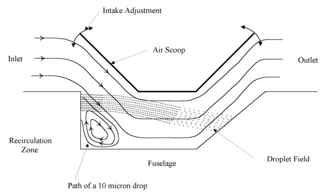
Figure 7. Schematic of the flow and frame geometry of the proposed high altitude UAV DHX.
The first generic facet of the design is a co-flowing geometry with inlet and exhaust on the top of the UAV fuselage. This basic geometry was chosen to as conservative as possible about fluid loss. A DHX places the heat transfer fluid directly in the external flow, with the possibility that some of the fluid can be lost to the external environment. Although for an aircraft flight the fluid can be replenished before each flight, the requirement for minimum mass implies that the fluid lost must be a small fraction of the total fluid reservoir. For the DHX shown in Fig. 7 gravity will prevent fluid from flowing out, except under the influence of aerodynamic forces, which have been designed to capture small droplets at the inlet, as discussed in detail below. Although counter- and cross-flow designs are more space efficient, the length of the UAV DHX is less important than the width, since the UAV fuselage is long for stability, but its width is limited. Counter- and cross-flow designs in turbulent gas flows also tend to drive 3-D instabilities that can lead to fluid loss, whereas the co-flowing design tends to damp perturbations into the downstream flow direction where the droplets will collide with the collection wall.
Co-flowing DHX's also allow the droplet/airstream temperature to become small for sufficient flow length. This is a tremendous advantage for the case of high altitude heat exchange. DHX's are usually designed to match the gas and liquid thermal capacities for most efficient heat transfer; the gas and liquid temperatures approach half the total temperature difference at the end of the DHX. In the present case, if there is much greater heat capacity in the liquid spray than there is in the gas flow, then most of the temperature change will be in the gas, which means that most of the heat capacity of the gas stream can be used. This is crucial for a high altitude UAV where the low gas density limits heat exchange. With this design a DHX can exhaust much more heat per area than a conventional tube and fin heat exchanger, which have flow heat exchange lengths limited by the drag of small passages.
The shape and location of the droplet field are directly derived from detailed FLUENT calculations. Initial designs began with a spray that filled the bottom of the DHX, moving parallel to its bottom. FLUENT indicated that the droplet field would be bent by the incoming cross flow, moving at an angle down into the DHX duct. This effect led immediately to the realization that during the initial merging of the flow and droplet field the gas flows through and across the droplet field. Thus with the design shown in Fig. 7 the spray could be compressed into the top of the DHX and the advantages of the co- and cross-flow designs can be combined. A large part of the cooling takes place where the temperature differences are the greatest, so a major part of the DHX heat exchange takes place in the initial cross-flow zone. Although this initially cools the top layer of droplets the most, the process reverses at the far end of the DHX, so that air/spray heat transfer is fairly uniform. The spray can then be concentrated at the top of the inlet plate and still have the entire airstream pass through the entire spray field. Shrinking the spray injector allows much smaller injector plate mass, as well as a smaller fluid manifold. Manufacturing is also much easier. Another crucial advantage of the design is that the intake flow recirculation zone captures small droplets (see a detailed discussion below).
There are other advantages of the modified design. Collection of the liquid is easier, because the liquid is spread out over a much smaller area and is concentrated near the gravity drain. Heat transfer is more easily adapted for operation at lower altitude as well. Originally three vertically separated spray injectors were to be used, where only the bottom injector would function at low altitude with the top of the DHX retracted so that flow was principally along the bottom of the DHX. With the modified design, as the intake flap end is lowered the flow penetrates the DHX volume less, but the decreased spray/flow intersection area is more than made up for by the increased air density. This simplifies the operation and construction considerably.
It has been a long-term problem of co- and counter-flowing DHX's to develop a means of efficiently joining the droplet and gas flows. Figure 2 shows the typical complexity required; a wide variety of spray injector heads have been designed to insert both the injector heads and the spray into the gas flow. Cross-flow designs (spray at right angles to the gas flow) avoid this problem, but have the problem that the upstream droplets absorb most of the heat, and without having a very long spray (and injector region) the droplet temperature cannot approach the airstream temperature. The proposed design combines the simplicity of a cross-flow DHX with the advantages of a co-flowing DHX.
The quantitative design of the DHX began with an extensive MathCAD symbolic calculation program that used to explore the design space of a DHX for the case of a high altitude UAV. Atmospheric properties as a function of density were entered from 16 to 38 km to explore the properties of the inlet air at different altitudes. The duct area was defined as 1 m wide by 0.5 m high. This area is consistent both with the heat transfer capacity of the low density air passing through the DHX and the heat transfer capacity of the droplet field. It is also compatible with the typical size of current UAV fuselages so that the DHX can fit in an existing aircraft without major redesign. A goal of 100 kW was defined, given the ERAST UAV baseline, and heat transfer as a function of liquid mass loading was calculated as droplet diameter is varied.
Parameters for the droplet field were then entered, including the space between holes, s, the number of holes, nh, the length of the DHX (1.5 m), the initial droplet velocity, vdi, the DHX height and width (1 m), and the liquid density (1000 kg/m3). A droplet diameter was then entered, varying from 0.2 mm to 2.4 mm. From these parameters the droplet frontal area, surface area, volume, and mass were calculated for all diameters. The droplet mass flow and droplet volume fraction, β , were then calculated. The mass flow was found to vary from 0.36 to 51 kg/s as the droplet diameter changed, and β varied from 0.007% to 1%. These parameters were used as a first cut at the final DHX design, and a result of iteration through the program to obtain a heat transfer power of 100 kw. The mass in the droplet field at any instant varied from 0.031 kg for 0.2 mm sized droplets, to 4.4 kg for the 2.4 mm diameter droplets.
The temperature gradients in the gas and droplet field were also based on global heat transfer approximations. The droplet size and mass loading controls these gradients. Most efficient heat transfer occurs when these gradients are matched, but maximal utilization of the enthalpy capacity of the gas results from overloading the liquid heat transfer capacity relative to the gas. The maximum gas Δ T design would be chosen for the 38 km altitude case, but has not been necessary for the 24 km case emphasized in the current work. From these calculations a rough overall heat transfer rate was calculated, resulting in an iteration on droplet size, initial velocity, and a DHX size that gave a heat transfer rate of about 100 kW.
An initial droplet size was defined to be 0.5 mm for heat transfer and droplet trajectory calculations. Generic droplet sizes for DHX's can vary from a few mm to a few tenths of a mm. This size range results from the fundamental fluid mechanical processes of a DHX. If the droplet is too large it will undergo uncontrollable break up into smaller sized droplets as a result of aerodynamic forces. If the droplet is too small it will be carried with the flow and not be captured in the collector for recirculation.
Within the acceptable size range of droplets a number of factors are important for the choice of droplet size. Overall heat transfer is dominated by the mass flux in the DHX (proportional to number x r3 x velocity), but the heat transfer rate is controlled by the total droplet area (r2), and the velocity difference between the flow and the droplets. Although smaller droplets transfer heat faster, they also speed up to the flow velocity faster, reducing heat transfer somewhat. Another dominating constraint is the need for having a practical number of orifices for droplet injection. Heat transfer rate needs drive the design droplet size down while the need for fewer orifices drives the droplet size up.
The droplet speed was defined to be about 10 m/s. The droplet speed must be small compared with the flow speed to obtain the maximum velocity difference and thus heat transfer. It must also be large enough to achieve the desired mass flow through the orifices so that adequate fluid is supplied to satisfy the heat transfer rate requirements of the overall heat exchanger. A speed of 10 m/s is believed to be a good tradeoff between mass flow rate and aerodynamic effects for a flow speed (vehicle speed) of 60 m/s for a typical UAV. Another important factor in the particular case of the UAV DHX is that the mass of droplets in the DHX droplet field at any specific instant should be significantly less than 1 kg. Higher droplet velocity and smaller droplet size reduces the mass needed in the field for a given heat transfer rate.
Preliminary parameters were then given to STI for an initial attempt at a detailed computational calculation of DHX performance. A coflowing droplet/gas (of differing velocities) field was assumed with the conditions given for the prototype except for a factor of 2 larger density and 70 m/s rather than 60 m/s. The field dimensions were assumed to be 0.3 m wide, 0.15 m high, and 1 m long. Droplet temperature was found to decrease from 100°C to 85°C while the gas temperature increased from - 50°C to 5°C. The heat power transferred was found to be 28 kW for a mass flow of 1.4 kg/s, and 7 kw for a mass flow of 0.2 kg/s. These calculations were extrapolated to a heat power of 100 kW, which implied a mass flow approximately 7 kg/s. Detailed FLUENT calculations showed that this mass flow rate resulted in a heat exchanger power of at least 100 kW at 25 km altitude for the size of the DHX described below and other parameters, extracting the maximum heat out of the airstream. Temperature differences of 10°C in the liquid and 130°C in the air are achieved, which is excellent use of the heat capacity of the airstream.
Low Mass Design. In the present case the overall constraint on low mass can enter into the droplet size design in a number of ways. There is a limit on the total mass of the injection apparatus, the mass of fluid in the system, and the mass of the recirculation and pumping system. Some of the tradeoffs are as follows: 1) The mass of fluid in the DHX for a given mass flow rate needed for heat transfer can be reduced by increasing the injection velocity; injection velocity is limited by the need for a large velocity difference between the droplets and the flow to achieve good heat transfer. 2) For the same mass flow rate, heat transfer is improved by using a larger number of smaller droplets; more and smaller orifices are required, increasing the manufacturing difficulties. 3) Heat transfer rate is proportional to fluid mass flow; high mass flow implies large pumping requirements and increased pump mass.
The above DHX design was very attractive. It used parameters appropriate to DHX design, it efficiently used the gas enthalpy, and the flow characteristics were good. Work then proceeded to the detailed estimation of the mass of the DHX components. The injector mass was reasonable, but then the system pump was sized and it was realized that 7 kg/s is a large flow rate requiring a large pump - too big to put on a UAV, although the UAV engine itself is one big pump.
As a result the DHX parameters were reexamined to reduce the mass flow rate, keeping the heat transfer rate the same. To reduce the mass flow while increasing the heat transfer per unit mass flow meant that a smaller droplet size should be used. A 1 kg/s mass flow was then specified, with a smaller droplet size (200 µ m vs. 500 µ m), such that FLUENT calculations gave a heat transfer rate of 65 kW. This was both an acceptable flow rate and droplet size. For the prototype design goal of 100 kW the flow rate was increased to 1.5 kg.
Heat Exchanger Comparison: Examining the heat exchanger parameters for the demonstrator UAV, given in Table 1, allows a direct comparison of the DHX with current best state of the art tube and fin heat exchangers. Total power required is about 140 kW. Total inlet area is 24.4 ft2, or 2.3 m2. Without entering into the details of coolant temperature, this means that for 7 kg/s, 500 µ m case the DHX can transfer the same heat power using about 1/3 of the frontal area (design transfers about 100 kW in 0.5 m2, although this pumping rate is probably impractically high for a UAV. For the lower fluid flow rate of 1 kg/s, 200 µ m diameter droplet case the DHX can transfer the same heat power using about 1/2 of the frontal area. These improvements result from the DHX achieving a much higher temperature difference in the airstream (100°C; air intake at 220 K, spray at 373 K) in spite of the lower heat capacity of vacuum oil relative to water. It should be recalled that the DHX was originally considered to be attractive because of mass savings, not heat transfer superiority. Furthermore the heat transferred in the above design is low quality heat, which is much more difficult to reject than the high quality heat that must be rejected from the compressed air used for engine combustion.
FLUENT Calculations: The two design conditions discussed above were simulated in FLUENT code runs at STI Optronics for the DHX geometry shown in Fig. 7. FLUENT accurately models the details of the droplet-gas two-phase flow, without the addition of turbulence. The code calculated the complete gas and liquid flowfields, the temperature gradients in each fluid, and the overall heat transfer rate. The input parameters for the initial, high droplet mass flow case were as follows:
Gas Properties: (US Standard Mean Atmosphere [CRC] at 24 km (80,000 ft))
Fluid: Air
Temperature: Tg = 220 K (-53°C)
Density: ρ g = 0.047 kg/m3
Velocity: vg = 60 m/s (135 mph)
Specific Heat: cpg = 1004 J/kg-K
Thermal Conductivity: kg = 2.0 w/m-K
Viscosity µ g = 1.61 x 10⁻⁵ kg/m-s
Droplet/Liquid Properties
Droplet Fluid: Dow Corning 705 Diffusion Pump Oil
Liquid Density: ρ g = 1070 kg/m3
Liquid Specific Heat cpd = 2000 J/kg-K
Initial Droplet Temperature: Tdi = 373 K (100°C - boiling water)
Initial Droplet Velocity: 5 m/s
Droplet Diameter: 0.5 mm
Total Droplet Mass Flow: 7 kg/s
Figure 8 shows the streamlines of the gas flow as it passes through the DHX. Figure 9 shows the velocity of the gas flow across the duct. The flow enters the DHX at 60 m/s and accelerates as it turns into and out
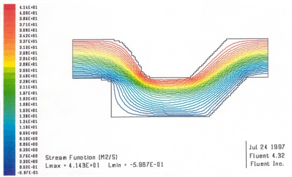
Figure 8. Streamlines for flow within the prototype DHX.
of the droplet field, as well as at the bottom of the duct, with higher accelerations at the top corners. The flow at the exit of the DHX has accelerated as a result of the heating of the flow, with one region as high as 125 m/s. The drag of this DHX configuration is thus significantly negative.
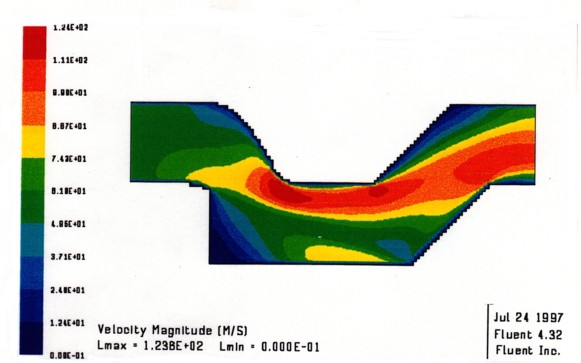
Figure 9. Contour plot of the gas velocity within the prototype DHX.
Figure 10 shows the droplet trajectories where the color indicates local droplet temperature that results from cooling by the gas flowing past the droplets. The droplets undergo most of their cooling in the initial cross-
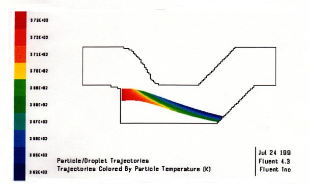
Figure 10. Droplet trajectories in the prototype DHX, colored by temperature for an injected temperature of 100°C.
flow region, but continue to cool as they flow with the gas toward the collection location. Note that there is a significant portion of the flow near the top of the DHX that does not interact with the droplet field. This can be reduced by aiming the droplets upward.
Figure 13 shows the heat transfer rate per unit volume within the droplet field. The most heat is seen to be transferred in the initial portion of the cross flow region as indicated from the droplet temperature distribution.
The concentration within the initial region is more clearly shown in this representation, however. The peak heat transfer rate is 1.83 x 10⁶ W/m3, decreasing to 7 x 10⁵ W/m3 outside of the initial interaction region, and falling to 1 x 10⁵ W/m3 over the second half of the droplet trajectory. Figure 11 shows the gas temperature distribution; most of the heating has occurred for the gas at the bottom of the DHX. The total heat transferred in the DHX is computed by averaging over particle trajectories. Multiple independent checks at both Thoughtventions and STI confirm the conclusions and the accuracy of the input parameters.
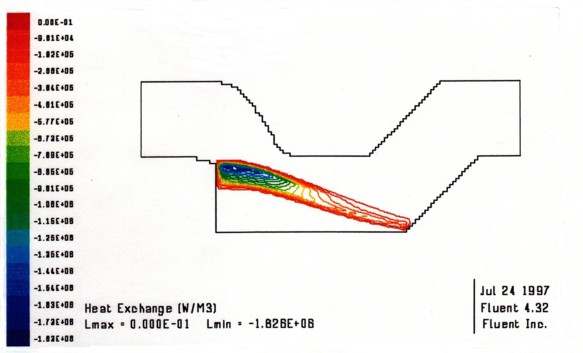
Figure 11. Heat exchange rate per unit volume within the droplet field.
Figure 12. Temperature distribution in the gas.
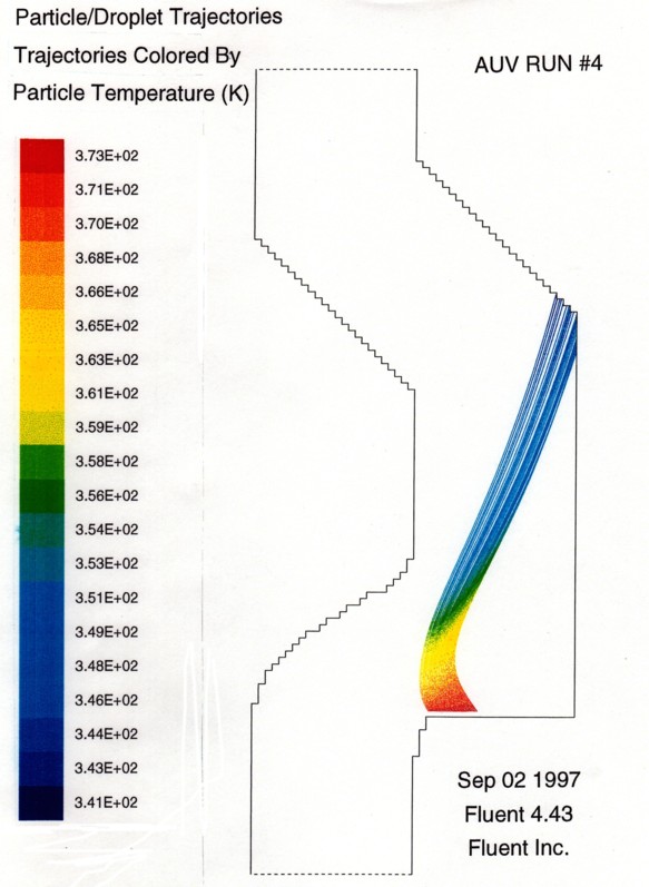
Figure 13. Droplet trajectories in the prototype DHX, colored by tempearture for an injected temperature of 100°C.
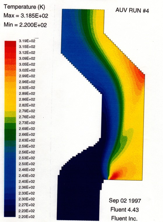
Figure 14. Temperature distribution in the gas for the 1 kg/s, 200µm diameter droplets.
SPRAY AND COLLECTOR DESIGN
The goal of the DHX spray design is to create a stable, uniform droplet field of the dimensions prescribed by the heat exchange design. There is a great deal of literature and research that has been done in this area; this work relies on extensive work done at STI to develop uniform droplet injectors for use in DHX's and other related uniform droplet devices.
The important physical processes that control the seeding and collection of the cooling droplets arise from the interaction of the liquid with its surrounding gas. First, the surface instability of a liquid column moving through a gas results in the formation of droplets. The droplets then move in response to a combination of their own inertia and aerodynamic drag forces. The droplet field in turn modifies the flow, and the turbulence inherent in the incoming flow as well as the unstable droplet wakes introduce a chaotic nature to the process. The droplets are large enough, however, that the turbulence as well as the steady flow does not change the overall dimensions of the droplet field.
Typical average flow streamlines and the droplet field through the heat exchanger are also shown in Fig. 7. The gas and droplet fields are merged by a turning duct in the gas flow, and then separated after the heat exchange has taken place by another turn in the duct. Droplet inertia forces are so much larger than drag forces that the droplets continue in a straight line and impact on the collector surface, where the cooled liquid forms a film and pool, and can be pumped away and recirculated. The droplet size, volume loading, and initial velocity together with the gas flow determine the path of the droplet field. The droplet parameters are determined by the fluid injection system, which, in this case, is a place with circular orifices spread over its face. The diameter of the fluid injection orifices, their three dimensional shape, and the pressure behind them determine the droplet size and velocity. Specification of the pressure, diameter, and orifice shape has been the subject of a great deal of research, as has the means for producing uniform droplets.
Uniform Droplet Generation. The processes of liquid jet breakup and spray formation have been widely studied [e.g. 10 and 11] are summarized in Fig. 15 as a function of the dimensionless Reynolds and Weber numbers. [5] The Reynolds number is the ratio of inertial to viscous forces, whereas the Weber number is the ratio of inertia to surface tension forces. The Weber number, We, is
We = ρ luj2dj/σ l3.2
where uj is the jet velocity, dj is the jet diameter, and σ l is the liquid surface tension. Various jet breakup regimes are shown in the figure, depending on whether the jet behaves in a viscid or inviscid manner, and whether the jet is sinuous (varying center location) or varicose (varying diameter but fixed center) as it moves away from the orifice. Some typical liquids are included on the figure for a range of liquid velocities from 1-3 m/sec and 500 micron diameter droplets.
Generally, droplets will break up into smaller droplets as a result of aerodynamic forces if their Weber number is greater than approximately 10. The surface tension of pure water in air at 1 atm is 72 dynes/cm2. Thus, for water there is a maximum stable drop diameter of 5 mm at a flow speed of 10 m/sec, and a maximum diameter of 50 microns at 100 m/sec. This is the size range appropriate for the UAV application. Drop size would be somewhat smaller for oils, since they have a surface tension of approximately a factor of two lower than water. These drop sizes can easily be aerodynamically separated from the flow at the appropriate flow speed - smaller drops can be separated at higher speeds. Average droplet sizes that are small enough to follow a 100 m/sec turning flow are on the order of a few microns or less. Some small droplets, known as satellite droplets, may be formed during jet breakup but their mass is proportional to 1/d3, so the mass loss as a result of their production and capture by the airstream is usually negligible - but not in the case of a UAV, as will be discussed below.
For jet Weber numbers above approximately 50-100, the character of the breakup process changes from varicose to sinuous. Varicose breakup usually describes relatively closely spaced drops with distinct, short, tapered filaments formed between the main drops during the final breakup stage. Sinuous breakup describes drop formation in which very long, almost constant diameter filaments form between the main drops during the final stage of breakup. One would expect that satellites would be more likely to form during a sinuous breakup than during varicose breakup and, thus, that jet Weber numbers less than 100 would be required for uniform drop formation. This expectation was verified by droplet injection experiments.
Figure 15. Liquid jet breakup parameters.
The practical limits of these parameters are imposed by consideration of the liquid injection orifice spacing, i.e., s > 0.5 mm and s/d > 2 (these limits are reached when the droplet size is small, the injection velocity is slow, and/or the droplet injection area is limited for high gas velocity); the liquid pumping pressure, i.e., Δ pd < 200 psi (i.e., violated when droplet size is small and/or the injection velocity is high); droplet breakup due to aerodynamic forces, i.e., Weber number, Wed,aero < 10; uniform droplet formation, i.e., 10 < Wej < 200, and splashing, ie., Wed,imp < 1000. For a vortex droplet DCHX, there are additional limitations such as droplet flow reversal, which become critical when the droplet's initial momentum is low relative to the counterflow gas velocity. The limiting criteria described above are by no means complete, but they do provide a realistic set of ground rules for studying DCHX concepts.
Given the range of droplet diameters that are aerodynamically stable and appropriate for heat transfer, and a total mass flow of droplets required for a total level of heat transfer, one must design a set of orifices and a means to drive the liquid through the orifices to create the droplets. Furthermore the liquid passing through the orifices must emerge as jets in such a way that only droplet of a specifice size are created without smaller satellite droplets.
The liquid flow rate through an orifice depends on the steady differential pressure across the injection orifice, on the fluid properties, and on the orifice geometry. In general, a discharge coefficient, C, is used to relate the mass flow rate, w, to the pressure differential, Δ p, through the expression for liquids
w = CAo [2ρ lΔ p/(1-β 4)]1/2
where Ao is the orifice area, and β is a geometry factor for the orifice. For geometries of interest for DHX injectors, β is small and β 4 is essentially zero. For Reynolds numbers above 30,000, the discharge coefficient is constant and well characterized. [12] A number of different regimes exist for Reynolds numbers below 30,000 [13] for which the discharge coefficient is not constant and can depend strongly on geometry and Reynolds number. Where the Reynolds numbers less than 50, the regime of interest for the DHX's appropriate in this program, the discharge coefficient for laminar flow is proportional to the square root of the Reynolds number, i.e., C= kRe1/2. Using this relation and mass conservation, one can show that
uo = [2k2do/µ] Δ p
Once the value of k has been experimentally determined for an orifice type and Reynolds number range, it is possible to predict the flow for other fluids through geometrically similar orifices in the same Reynolds number range.
Injector Design. There is much past injector design work [e.g. 14 and 15] that will be taken advantage of within the context of the viscosity and surface tension of the liquid that will be considered for use in the heat exchanger. A wide variety of nozzle designs and droplet generation techniques are available. Droplet mass loading in the airstream is set by the number of orifices and the injection pressure that results in the liquid jet velocity.
The simplest form of injector appears practical for this application - a pressurized reservoir behind a simple small hole. Hole sizes of 200 microns in diameters are easily made, a size that will lead to droplet a size of approximately 400 microns with some dispersion, which is acceptable in this application. The injection velocity (and spray penetration for cross-flow injection) is determined by the driving pressure. Low pressures (150 kPa) would be appropriate for 10 m/s injection speeds, whereas high pressure systems would be necessary for 100 m/s speeds. Air-assisted injectors will not be appropriate, since they generate micron-sized drops that are suitable for evaporation but not aerodynamic capture of the droplets. It must be emphasized that the droplet field injectors are simple and are difficult to fabricate only because of the large number of holes and the need to impose oscillations on the jets to create uniform droplets.
This program is taking as a starting point extensive work that has been done in the last five years at STI to create a droplet field to create an excited oxygen fluid dynamic laser. [2] This droplet injector consists of 12,000 holes, has a significantly higher droplet velocity and smaller droplet diameter (both experimentally more difficult to obtain) than the design proposed here. Very uniform droplet size distributions have been obtained by a proprietary system that transversely excites the orifice plate. The orifice plate, in turn, has been developed such that machining techniques provide the necessary high quality and properly shaped orifices for achievement of uniform droplets. The initial design requires about 4 of these now standard injector systems, with many fewer holes in each injector segment.
Insight into the tradeoff between droplet diameter and the number of orifices required for a given heat transfer is shown in Fig. 16 for the high and low temperature radial DHX shown in Fig. 4. Large droplets require few orifices, while small droplets can require a prohibitive number of orifices. This particular DHX implies a minimum practical droplet diameter of 150 µ m for a low temperature DHX and 75 µ m for a high temperature DHX. The prototype UAV DHX in the co-flowing case is designed for a 200 µ m diameter droplet size, and has a quite reasonable number of orifices.
The primary goal of injector design for this program is to design a low-mass system that still meets the heat transfer requirements. The generic design is well defined: 1) a droplet field generator consisting of perhaps four orifice plates with fluid pressure or transverse plate oscillations that induce perturbations in the flow to give uniform droplets, and 2) a collection system consisting of a grooved surface draining by gravity into a pumped pool at the bottom of the DHX.
The design and droplet production of a single orifice in the DHX is shown in Fig. 19. The fluid passes from a low velocity manifold out of the excited orifices, forming a perturbed jet that breaks up into uniform droplets. If shaped with a bellmouth type inlet section, the holes can be made with an L/D of approximately 2,
Figure 16. Chamber diameter and number of droplet injector orifices as functions of droplet diameter in high and low temperature DHX's of type shown in Fig. 4. Line with cross hatching denotes central manifold diameter. [3]
which means that the injection plate can potentially be very thin. The injection plates in the STI droplet injectors are machined from metal. A lightweight design would probably use molded plastic holes. A sowing machine type device using a hot needle might be used to make the holes, and then the surface would be joined to a honeycomb backing. The passages in the honeycomb would be flow passages, and they would be oriented parallel to the oscillation direction to maximize stiffness along that axis. The primary question would be one of stiffness and avoidance of unwanted vibration. All of this seems practical.
Fluid Loss. A DHX is necessarily an open system, mixing liquid droplets at one temperature with a gas field at another temperature. The liquid is recirculated and the gas that has heat transferred to it is ejected from the DHX. The heat source and atmosphere define the temperature difference between the media. The amount of heat that must be transferred determines the mass flow rate, whatever the size of the DHX. The mass flow rate determines how rapidly the droplet field is recirculating. The recirculation period, together with the total operating time of the DHX determines what fraction of each droplet field can be lost from the DHX. There are a number of mechanisms by which liquid can be lost to the gas stream; direct droplet loss, splash droplet loss, and evaporation, are major possibilities. In the UAV application, not only can no fluid be added, but no major fluid reservoir can be carried on the UAV as a result of the need to minimize its total mass.
Droplets can be lost directly out the exhaust either by being directed there or by being carried out by the flow. The injectors are constructed so that 100% of the design trajectories remain in the DHX. Furthermore, normal turbulent fluctuations are not sufficient to move nominally sized droplets out the exhaust. Extensive work has been done on uniform droplet generation, including a great deal of experimental work. Theory and experiments show that practical devices make 100 % uniform droplets without satellites. Non-ideal processes cannot be ruled out, however, so the remaining mechanism for droplet loss is that smaller droplets that would be carried out of the DHX by the flow might be generated at some location in the DHX. Discussions with STI have indicated that work there has not concentrated on the non-idealities of the droplet field to the extent that will be necessary for this program to prevent fluid loss in the DHX proposed in this program. Open systems have not been operated with the newly developed spray designs.
Fluid loss can clearly be important based on the number of droplet fields that would pass through the DHX during the flight period. For a typical 10 hr flight and a 10 m/s droplet speed accelerating to 30 m/s in the flow, a droplet will pass through the DHX about 6 x 10⁵ times. If a loss of 1 kg mass of fluid is allowed over the flight and perhaps 0.5 kg is in the droplet field, then only 0.001 % of the droplet mass can be lost during each pass. In terms of number of droplets, about 400 of the 0.2 mm droplets can be lost during each pass, whereas only 2 drops out of a 1 mm diameter droplet field could be lost. For an ideal DHX with a perfect uniform droplet generator, no drops at all are lost, but evaporation, as well as non-ideal processes must be considered.
There are a number of non-ideal spray processes that might contribute to fluid losses. These can be categorized as 1) Satellite droplet production, 2) Droplet collision effects, and 3) Non-ideal orifice shape effects.
The most easily controlled process is the production of large droplets with enough transverse velocity that they pass out of the DHX without hitting the collector wall. Current machining techniques are accurate enough so that improper hole angles that arise from aberrant holes can simply be identified and sealed off. The length to diameter ratio of the holes is such that transverse velocity fluctuations arising from the injection process are small compared with that needed for droplet escape. Droplet collisions are minimized by fluid mechanics that tends to separate droplets when they approach each other; a decreased distance increases flow resistance between the drops, decreasing flow speed and increasing flow pressure, driving the droplets apart. Since the droplets are all at similar speeds, any collisions that do occur, tend to be coalescences. Splash from droplet impact on the collector surfaces should be unimportant because of the low mass of the droplets. To reach the exhaust, splash droplets must also penetrate the boundary layer next to the plate, otherwise the droplets will be captured by the lip at the exhaust section. This should be a small factor, but the phenomenon will be investigated further. It is concluded that mass loss of the fluid will not be significant, but this must be verified experimentally.
The primary question for fluid loss is the generation of satellite droplets; droplets smaller than the nominal size can be generated by a variety of processes. The number and size of these satellite droplets in a real DHX would determine the total fluid loss. Production of satellite droplets is common in unexcited spray creation. As the liquid jet column becomes unstable and surface tension forces neck the column down, all of the fluid is not able to be drawn into the nominally sized droplet and forms independent, smaller sized satellite droplets between the larger droplets. The satellite droplets are of a size that follow the flow much more than the nominally sized droplets, so that they are much more likely to be lost from the DHX when the gas flow exits. These satellite droplets contain much less mass than the nominally sized droplets. A satellite droplet with a diameter 1/4 of the nominal size will only have 1/64 of the mass of a standard droplet, but as has been described above, only very small mass losses are tolerated in this application. The primary detrimental effect of droplet collision will also be in the production of satellite droplets.
Based on extensive work at STI on the generation of uniform droplet fields, it can be stated that using their technology, satellite formation almost undetectable; in the range of very small fractions of a percent. Using a photodiode to measure droplet sizes being generated by an orifice, data showed that silicone drops could be made essentially free of satellites or nonuniform drops by applying a sufficiently large vibration signal. The vibration amplitude required to eliminate nonuniformity (» 990 pa or 0.24 psi) was much larger than that which caused transition from random to regular breakup (» 60 Pa or 9 x 10⁻³ psi at this test condition) for the silicone fluid. A reduction in vibration amplitude by approximately 20 percent generally resulted in more than 5 percent of the drops having satellites or nonuniform diameter. Further reduction in vibration amplitude would result in increasing numbers of satellites and nonuniform drops, but the main drops formed very regularly at the excitation frequency. This characteristic of the lower viscosity (silicone oil) tests was markedly different from the variation in jet breakup with vibration amplitude observed with the high viscosity fluid (glycerine water). Further proof of an ability to generate a droplet field without satellite droplets has been demonstrated by droplet field imaging at STI that show consistent examples of a uniform droplet field with many droplets, but no satellite droplets.
A major advantage of the prototype DHX design shown in Fig. 7 is its effect on satellite droplets. The flow field enters the DHX at an angle, initially passing across the droplet field before it turns at the bottom of the duct. As is indicated in Fig. 7, there is a recirculation zone at the bottom upstream corner of the DHX. As the initial cross flow passes through the droplets, any small satellite droplets are preferentially carried down into this recirculation zone and captured. The FLUENT calculations give this type of path for all small droplets emerging from any location on the injector; the path is inherent in the nature of the smaller droplets to more closely follow the flow, so they get preferentially swept into the recirculation zone.
Another possibility for fluid loss is evaporation, but this type of fluid loss is avoided by using a low vapor pressure fluid and relying on droplet cooling to further lower evaporation. For evaporation, low mass loss means that only a small fraction of the mass can be allowed to evaporate over a 10 hr flight time. Vapor pressure calculations show that high vacuum oil is an acceptable only candidate fluid. Although at 120°C the mass of vapor in a 0.5 m3 droplet field using Dow Corning 705 silicone vacuum oil would be 2.7 kg, the critical temperature is the final temperature of the droplets. At the exit of the heat exchanger the droplet temperature has dropped to at most 80°C, at which temperature the mass of vapor lost is only 0.055 kg, an insignificant value. The droplet exit temperature is the important temperature, because the droplets are in such intimate contact with the air that any vapor is in equilibrium with the droplets, and vapor boiled off initially in the DHX recondenses on the droplets. STI has confirmed these results experimentally. The heat of vaporization is small compared with the overall heat transfer, and is thus not a factor in the heat exchange process. Thus, mass lost through liquid evaporation is not a problem in this application. However, the possibility of fluid evaporation does constrain the fluid to be high vacuum silicone oil. Evaporation also constrains the overall DHX configuration to the coflowing geometry. In the counter and cross flowing geometries, the hot droplets would be exposed to gas that immediately exits the DHX and would carry out too much fluid mass.
Droplet Drag. Droplet drag was calculated to determine how quickly the droplet is accelerated up to the gas speed in the DHX at atmospheric conditions, and to determine the effects of turbulence and recirculation flows on the droplet size chosen. Droplet acceleration plays a significant role in reducing the overall mass of fluid in the DHX, because this acceleration increases the spacing between droplets and lowers the mass density once the droplets fully penetrate the gas flow.
Collector Design The entire DHX design is centered on fluid collection as a result of the need to retain all of the total fluid in the UAV and the need for a minimum mass DHX. The DHX (Fig. 7) has been designed as a container with an enclosed bottom with flow inlet and exhaust at the top. It uses gravity flow of droplets colliding with a slanted wall for collection through a single or limited number of drain holes. Gravity has a minor effect on droplet paths, but collection at the bottom allows any other liquid in the DHX to eventually reach the drain and be recirculated. The simple drain hole also removes the need for complex porous plate suction designs with their attendant complexity and mass. The collection design is basically simple, but a concern is fluid hold-up in the DHX. This is difficult to calculate, and will be a function of the slope of the sides, the thickness of the film, and the viscosity of the liquid. The question is how fast will the fluid drain down into the collection holes. To minimize most of the hold-up, the location of the droplet impact should be a steeply sloped trough, which should
not affect the fluid mechanical properties of the overall DHX. However, the concentrated droplet field should hit a relatively small area for collection, as shown in Fig. 7. Additional design notes include grooving the end wall to minimize splash, and to install a sharp lip on the top to prevent loss of film or marginal droplets. It must also be noted that the DHX need not be a totally open system. There can be fluid catcher screens at the gas exit of the device, as long as these do not add too much to the overall mass or drag of the DHX. It is not believed that this will be necessary in the present case.
Droplet Heat Exchanger Engineering Design
This part of the work has been to investigate the engineering details of the proposed DHX design. The goals were:
1) To establish what all of the specific components of an operating DHX are.
2) To clearly demonstrate that the specific devices that make up the DHX components for a UAV can be built is a practical system.
3) To define these components to the extent that their mass could be estimated.
4) To define detailed component designs for a prototype DHX.
In some sense this work should be the final goal of the program, since for a radically different system the reduction from theory to practice is usually the downfall of a proposed system. However, the assessment of the applicability and appropriateness of a droplet heat exchanger to a UAV is the final measure of feasibility for this program and has been addressed. The results of the feasibility analysis were then used to assess the engineering feasibility.
The details of the droplet heat exchanger design discussed above determine both whether fabrication is practical and whether the proper amount of heat can be exchanged within the physical constraints of a UAV environment. The further requirement of design for low mass requires major changes in the overall design. For the entire DHX to have a low mass requires not only that all of the DHX components separately must be low mass, but that together they must be less than the mass of a comparable tube and fin heat exchanger system. The mass comparison is not only with the tube and fin heat exchanger itself, but with the entire system associated with the tube and fin heat exchanger. This includes the water pump, plumbing, the heat exchanger, the support structure and the ducting required for mounting in the UAV. These two systems are very different, so components of each may weigh more or less compared with its counterpart.
The engineering details of the prototype thus consist first of the details of the generic system and its components, and second of the details of a minimum mass design for these components. An example of the way minimum mass design can affect the overall design is the change of the total droplet mass flow during program work from 7 kg/s of 500 µ m diameter droplets to a 1.5 kg/s of 200 µ m droplets. The higher mass flow rate is more efficient in terms of the utilization of the heat capacity of the air at high altitude, but although the system fluid mass can be kept small in both cases, the pumping requirements of the high mass flow case make the overall mass of the system prohibitive because the volume of fluid that must be pumped is so large.
The droplet material will be Dow Corning 705 diffusion pump oil. This is one of the few fluids with low enough vapor pressure such that mass loss from evaporation is insignificant during the flight time. This is an expensive fluid, however (5 gal. => $5,500 in 1992), so DHX performance must be analyzed to determine if DC 704 fluid will also be acceptable. If the vapor pressure of DC 704 is low enough at the DHX exit temperature, then the lower cost and lower viscosity of this fluid can be taken advantage of. DC 704 and perhaps even cheaper fluids can be used in the initial debugging stages of a prototype fabrication program.
The following describes the low mass design of the components of the DHX system, and compares the mass of each component with its tube and fin heat exchanger equivalent to the extent possible. DHX's have not previously been designed for low mass, so much of the design will be novel for a DHX, but the design will not involve totally new technology. Major component development programs will be avoided by using established technology from other technology areas. Such technology has not been used because it is either more complex or more expensive.
DHX system components consist of: 1) the droplet injector, 2) the DHX box, and 3) the fluid recirculation system. At the end of the design discussion, an overall estimate of mass reduction for the DHX compared with the ERAST demonstrator tube and fin heat exchanger will be made.
Droplet Injector - Although fundamentally different from existing radiator technology, droplet heat exchangers can make use of well developed existing technology from many unrelated sources [4]. Developers of ink jet printers have extensively investigated principles of droplet generation and collection. These printers use pressure forces the working fluid through thousands and sometimes millions of extremely small orifices. The fluid emerges from each orifice as an unbroken jet that liquid jet instability breaks into spherical droplets. A critical factor in the fabrication of droplet generators is to make highly parallel orifices. The best letter-quality ink jet printers have a 2.0 mrad trajectory accuracy with up to 220 orifices 25 microns in diameter in one print module. These specifications are similar to those for a droplet heat exchanger except that the holes in the heat exchanger are larger and more widely dispersed.
The technology presently exists to inexpensively fabricate the spray injector systems needed for a droplet heat exchanger. The numbers of holes (up to 106) and total piece dimensions (totaling 0.5 m x 0.5 m) have already been demonstrated for other applications.
The basic DHX injector will consist of one or more flat plates that extend over the base width of the DHX as shown in Fig. 16. Given the heat exchanger design described above, the specifications for the injector plates are:
Orifice diameter: 100 µ m (droplet size 200 µ m)
Injector Size: 0.5 x 1.0 m (0.036 m2)
Number of orifices: 14,000 total
Orifice spacing: 3.2 mm (square)
Jet Velocity: 12 m/s
Total mass flow: 1.5 kg/s
A design of a droplet injector based on STI's currently well developed technology is shown in Fig. 17. This design is a conservative approach that uses tested STI injectors. The injectors are sized to optimize vibrational stability for the largest orifice area. There are two pairs of injectors, each pair vibrated by a single piezo electric driver assembly to minimize driver mass. The injector plate sizes are 0.24 x 0.15 m (0.036 m2), there are 3500 orifices in each plate, and the transverse driving frequency is about 24 kHz. The driver frequency is determined to give uniform droplets. The details of this calculation are proprietary to STI.
The orifice spacing in this design is fairly spread out, since the orifice separation is 30 times the hole diameter. This is somewhat inefficient and may be reduced by decreasing the vertical height of the injectors more. Further work will be required for this optimization. Narrower injectors require less extensive manifolding and the piezo drivers have less mass to vibrate. However the denser droplet field may interact more with the flow so that the droplet field is pushed more toward the bottom of the DHX such that it intersects less of the flow. This issue can be resolved by more FLUENT runs.
Acoustic pressure driving is another option for forcing the oscillations in the jets that result in uniform droplet formation. The power and frequency required are similar (about 500 W) but acoustic driving has the advantage of being able to use a single driver for the entire injector assembly. A single driver system might have considerably less mass.
The choice between acoustic and transverse driving will also be controlled by the frequency response of the injector plate structure. A honeycomb structure should be more stable than the simple plate currently used in either case. The 25 kHz frequencies required should be well above any kind of fluid mass oscillation. However the used of pressure oscillations will affect the entire injector structure whereas the transverse oscillation technique need only be applied to the injector plate itself. The decision about which technique to choose will depend on the status of each technology when the prototype is fabricated.
Low Mass Design There are three parts of the injector that can be designed for minimum mass: the injector plate, the injector driver(s), and the fluid manifold supplying the injector plate. The injector structure support the forces associated with supporting the weight of the assembly, the forces developed by fluid pressure needed to generate the 12 m/s fluid jets, and the vibration forces needed to drive uniform droplet formation. The
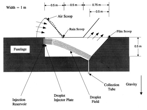
Figure 17. Cross section of prototype DHX showing droplet field geometry and fluid capture features.
structure must provide the material from which the orifices are formed, and it must provide a liquid reservoir behind the injection orifices to supply them with adequate fluid. The orifices must have solid walls that form a smooth converging entrance region and straight channel. The injector plate must also fabricated in a way that allows large numbers of orifices to be added to it. The orifice structure must be made such that resonant modes at other frequencies are not excited by the system that forces uniform droplets to be made.
Low Mass Injector Plates Injector plates are currently made out of steel, which is much too heavy for this application. Aluminum is an obvious candidate metal, since it is easy to machine and a light metal. Plastic is the most attractive candidate, however, since it is much lighter than aluminum (specific gravity of 1 vs. 2.7). An obvious possibility is to use the front face of a plastic honeycomb material. This also has the advantage that the channels of the honeycomb can form the manifold for the fluid flow. The injector plate must also be thick enough to provide the orifices needed for uniform droplets. For the present design case this is not an issue. For an L/D of 2 hole with 100 < µ m diameter orifices the plate only need to be 0.02 mm thick. It will be considerably thicker than this, so making the L/D larger is a natural option. An L/D of 5 would remove the necessity for a rounded intake and allow the holes to be drilled by laser from the outlet side. This avoids having to drill the injector plate and then attach honeycomb to it, and laser drilling is much cheaper than the EDM technique that is currently used (and wouldn't work for plastic).
Taking as an example plastic honeycomb material with a 0.5 mm thick orifice sheet on one side would have a mass of about 1.5 kg/m2 (see box material discussion below). The injector plate would then have a mass of (1.5 kg/m2)(0.15 m2), or about 0.22 kg. To this would be added the mass for the fluid manifold structure and the mass of the fluid itself. The injector plate must also have adequate stiffness to maintain the pointing of the orifices, but the sample obtained during the project are stiff enough.
Low Mass Drivers The power supplies currently used to drive the injector plates are standard power 500 W power supplies, and thus fairly massive. The piezo drivers require high energy capacitors, which are heavy if standard capacitors are used. A 500 W power supply can be designed to be low mass, however, using resonant SCR drivers, for instance. The heavy part of these units is primarily the transformers and to a secondary extent the capacitors. Neither frequency nor voltage precision is required, and frequency stability is not critical as long as the
Figure 18. Schematic of STI transversely excited droplet injector design.
frequency is pure, which is easily achieved using resonant circuitry. A supply with a mass of less than 0.5 kg should be easy to build, especially since in the last few years high power high voltage SCR's have become commercially available. The details of the power supply will depend on the type of power available in the UAV. There will be some additional mass from increasing the instrumentation power requirement by 500 W.
The mass of the piezo drivers themselves can also be estimated. For a 100 µ m diameter orifice, and a 50 µ m radius, an oscillator amplitude of approximately 5 µ m should be adequate to generate uniform droplets. Piezo electric strain is typically 1.6 x 10⁻⁴, and assuming that driving this at resonance gives a factor of 3 greater displacement implies that a 1 cm stack can drive the displacement needed. A 10 mm x 6 mm plate at each end of the injector plate as shown in the figure would drive the honeycomb injector plate, which would mean 4 total of these sets. This would imply a total piezo volume of (4)(0.6) cm3, with a specific gravity of about 8, or a total mass of 20 grams. Thus the power supply itself will be the mass limiting part of the driver supply.
One interesting note concerning the driver is that given the flow configuration that captures small droplets, the requirement for uniform droplets without satellites may be able to be relaxed significantly. For instance, if approximately the same number of droplets were generated with a 50% size range variation, the heat transfer would be very similar, and it might not be necessary to drive the orifices at all. A difficulty with this approach, however, is that if a significant number of droplet are deposited elsewhere in the DHX than in the collector, the mass holdup in the device will begin to become a significant mass over the 10 hr flight duration and may be unacceptable. The possibility of undriven injection will be investigated in the future.
Low Mass Manifold The fluid manifold must provide a large scale inlet for the fluid, and flow passages to the many droplet orifices such that the pressure drop in the manifold is relatively small. A large pressure drop relative to the pump pressure would result in lower velocity droplets. To minimize the pressure drop implies that the total cross sectional area of the supply passages should be 2 to 5 times as large as the total cross sectional area of the orifices they supply. Assuming four feed lines to the 1 m wide, 15 cm high injection sections, a flow rate of 1.5 kg/s 10 m/s through the orifices implies a total orifice area of 1.5 cm2, so that a 1.5 cm diameter feed line for each of the four sections should be adequate. Each feed line then supplies an area 15 cm by 25 cm. If the average thickness of the liquid film feeding the orifices is 2 mm, then based on a calculation of the fluid volume in the manifold, the mass of fluid in all four manifolds is (0.2)(100)(15) g, or 0.3 kg, an acceptable figure. If the manifold transition between the 1 cm diameter feed line is a bellmouth near the manifold the fluid velocity can be reduced there to acceptable levels; between 1 and 2 cm diameter the manifold thickness should be 3 mm. This all seems reasonable. Furthermore the manifold can be made out of the honeycomb that functions as the DHX walls; the honeycomb channels can be the manifold. This also has the advantage that the pressurized fluid stiffens the honeycomb and aids its support of the injection forces. This specifies that the honeycomb thickness be about 2 mm. The sample discussed below has a thickness of 4 mm, so this size should be easily done.
Droplet Field Mass The mass of droplets in the droplet field can readily be calculated. For a 1.5 kg/s mass flow, a 20 m/s average droplet velocity (droplets accelerated by the flow), and a DHX length of 1 m, the droplet field mass at any instant is approximately 0.1 kg.
The total mass of the injector system including droplet field is thus estimated to be approximately 1 kg. This compares with the tube and fin radiator mass of 7.5 kg. The walls of the DHX box are not included in this comparison because they are competing with the duct walls and supports for bring the air to the tube and fin radiator.
DHX Box Simple calculations show that if a metal shell is designed for the DHX the entire DHX is fairly massive. A self-supporting metal should be about 1.5 mm thick. A box 1 x 1 x 2 m made of aluminum would have an area of 10 m2 and a mass of 40 kg. Two critical realizations are appropriate for a mass comparison with a tube and fin radiator system. The first is that the tube and fin radiator requires ducting to bring the air to it if it is internal to the UAV, or massive supports if it is external to the UAV. In either case this supporting mass is large, and it is this mass with which the DHX should be compared, rather than the tube and fin radiator itself. Furthermore, the constraints on the DHX box walls are much simpler than are similar constraints on the tube and fin radiator ducting. The DHX walls are straight and flat, rather than possessing complex curves. The basic requirement is only that the walls support themselves and the small aerodynamic pressures generated by the flow through the DHX. There is no need to use metal. Porous, high strength, low density materials can be used in stead. High strength foams or honeycomb can be used with thin plastic sealing coatings for the internal walls, as well as for the piping and pumping systems of the DHX.
Shell Mass: The proposed DHX box is 0.5 x 1 x 1.5 m, not including the top, which is a part of the fuselage, implying about a 4 m2 wall area. Assessing first the wall mass, contact was made with Bellcomb Technologies (Minneapolis, MN), specialists in lightweight commercial honeycomb material. The material options begin with dirt cheap (under 2 $/ft2) laminate backer honeycomb that has a mass of 3.6 kg/m2, and continue with materials that decrease in mass per unit area while they increase in cost per unit area. Four standard 10 cm2 samples were received: 1) Aluminum (Al) face both sides with fiberglass filler with a mass of 6.2 kg/m2, 2) Al face both sides with styrofoam filler with a mass of 6.9 kg/m2, 3) Melamine plastic both faces with paper honeycomb core with a mass of 3.1 kg/m2, and 4) ABS face one side plastic honeycomb on back with a mass of 1.9 kg/m2. The lightest of these standard materials would give a total of 7.6 kg for the DHX box. All of these samples are more than stiff enough to be self supporting over a 50 cm length. Eliminating the 1 mm thick ABS plastic face from the lightest sample implies a 0.7 kg/m2, should provide adequate strength and stiffness, to result in a total mass of 2.8 kg for the box. The joints at the corners will add some mass, but presumably a small fraction of the total mass. It is possible that this figure can be further reduced, but there seems no question that this mass is well below the comparable mass of the tube and fin radiator ducting. The ducting in a UAV tube and fin radiator system is requires the radiators are large and internal to the fuselage, using an air scoop to capture the requisite amount of air for radiator cooling, and an exhaust hood to pass the air back into the atmosphere. There is a large amount of duct work with complex shaping. The mass of this ducting and supports should be considerably greater than that for the DHX.
Rain Scoop One of the ancillary questions about a DHX operating in a real environment is how it would avoid contamination by rain, snow, or dust. These conditions are only a factor at low altitude, and assume that the UAV would fly in rough weather. This is probably not likely considering the fragility necessary for a light aircraft with a very large wingspan. However a rain collector can be added using a water collector at the bottom of the open intake flap. This design takes advantage of the same aerodynamic droplet properties that the DHX uses. If the droplets are large enough not to be carried with the flow they will hit the intake flap, form a film, and can be carried out a bottom duct. If the droplets are small enough to be carried with the flow they will pass directly through the DHX.
Collector - The FLUENT calculations show that the droplet field will impact on a fairly small area at the bottom end of the DHX box. The droplets will impact the wall, form a liquid film, and the liquid film will flow by gravity into a reservoir. The reservoir fluid can be then be pumped by the recirculation system. The reservoir will be sloped in both dimensions to promote rapid flow.
Neither the collection or rain scoop systems should contribute significant mass to the overall system.
Fluid Recirculation system The pumping power required to circulate the liquid through a typical droplet heat exchanger is modest, such that parasitic power losses will be a small fraction of the total heat transferred. Similarly the mass of the pumps and pump motors will be proportionally small compared to the shell mass of the heat exchanger. [6]
Pump and Piping Mass: This mass must be estimated relative to tube and fin radiators, which would also require a pump and piping. The pump associated with the ERAST demonstrator water cooling system moves 4-16 gallons per minute (GPM), or 60 liters/min (L/m), or 1 l/s. The proposed system needs to move 1.5 kg/s of specific gravity 1 fluid, or 1.5 l/s, which is a 50% larger volume of fluid. The pump size can be estimated based on standard engineering formulas. The pump power required = (1/efficiency) * Volume flow * Pressure drop. For 1.5 kg/s flow at 10 x water viscosity through 100 micron orifices, and an efficiency ~ 0.6, the pump power is estimated as about 0.75 kW or ~ 0.75 hp. The pressure drop is about ~ 50 psi or ~ 100 ft of head. This is a fairly small pump, perhaps 7" x 5" x 11" ; $1500 and 15 lb, or 7 kg. This is standard technology, and not a lightweight pump. The pump mass does not scale directly with mass flow rate. A 50% higher mass flow rate would only be perhaps a 25% higher mass pump, which implies perhaps 2 kg extra mass. This is a minor increase compared with the estimated 10 kg of mass saved by the injector and DHX box.
The fluid in the piping system should be comparable, since similar volumes of fluid must be moved similar distances.
A high altitude UAV is an unusual application as far as heat transfer is concerned, because by definition the DHX is necessarily mounted behind a very large pump - the aircraft engine. The possibility of increasing the engine size significantly to provide pumping power so that more heat can be transferred to the airstream is an intriguing one. At any rate it probably makes the added mass for added pumping an even smaller number, since the added pump power is such a small fraction of the aircraft engine power.
This may be also route to very high altitude heat exchange. It has been discussed that achieving much higher droplet mass flow rates allows much improved heat exchange using a DHX. If much greater pumping power were added to the engine the heat exchange capabilities could be greatly increased. The added requirement for intake air, which must be highly compressed may be a problem, however.
DHX Oil/water Heat Exchanger An associated question for the overall design is thus how to perform the heat exchange between the engine cooling fluid and the high vacuum silicone oil of the DHX. Ideally the vacuum oil would be used directly as an engine coolant, and this may be possible in the supercharger. However, a totally new engine would have to be designed to use only high vacuum oil because current designs have cooling passages in the head and block that would not permit sufficient flow for the higher viscosity vacuum oil. The coolant pump would not be appropriate either. The redesign would not be that difficult, but different engine cooling passages would be required with a different block and head casting.
UAV SYSTEM FEASIBILITY
The demonstration of feasibility of applying a DHX to a UAV consists of showing that a DHX can perform heat exchange comparable to the state of the art tube and fin heat exchanger technology for a UAV, but with a DHX device that has a significantly reduced mass. During the program work that pursued this goal it was realized that a DHX can also function as a significantly superior heat exchanger at high altitude compared with a tube and fin design. This superiority results from the ability to use more of the heat capacity of the air at high altitude; this will be critical for a UAV to be able to achieve very high altitude flight (up to 30 km).
The first step in the feasibility demonstration was the establishment of a baseline case for a state of the art tube and fin heat exchanger for a UAV that could be used for comparison.
The design altitude is about 25 km, flight speed is about 60 m/s (135 mph), flight time is about 10 hr, and the aircraft will be powered by a supercharged (3 stage) nominally 80 hp Rotax piston engine. The engine supercharger provides 1 atm air to the engine and requires very substantial heat exchangers itself. The overall vehicle has a fuselage diameter on the order of 1 m and a large wing span and wing area to achieve this high an altitude. Total vehicle weight is about 900 kg (2000 lbs). Heat rejection is done by air-metal convection cooling using lightweight tube and fin radiators. Design of this type of device is described in such texts as Compact Heat Exchangers by Kays & London [8].
The flight, engine, and cooling parameters for the demonstrator UAV are as follows:
Rotax 912 engine: Heat Power
..............................................................................(BTU/s).................(kW)
80 hp engine cooling:............1. radiator.............85.4..............90.0
................................................2. oil cooler...........17.2..............18.5
3 stage supercharger
cooling:...................................3. intercooler (28)........4.9...........5.2
...............................................4. 2nd stage...............12.4..........13.1
...............................................5. aftercooler.............12.5 .........13.2
Tube and Fin Radiator Parameters:
Size:............Air Mass Flow...................Radiator Mass (with fluid)
(Square - ft x ft)...........(lbs/s).......kg/s..........(lb).............(kg)
............1. 3 1/2 ...............4.9............2.23............15.4..............7.0
............2. 1.7..................0.8............0.36............7.3 .............3.3
............3. 1.5..................0.13...........0.06............7.6..............3.5
............4. 1.75.................0.35...........0.16............8.25.............3.8
............5. 1.98.................0.18...........0.08............7.6..............3.5
Engine radiator coolant: 200°F saturation temperature, 15-18 psi, 4-16 GPM
The radiator requires the largest heat and mass flow, but the other coolers together require only 55% less. The air mass flow numbers are consistent with the radiator frontal areas, assuming 0.05 kg/m3 air density, and a flow speed of 60 m/s. This means that the radiators must capture a total frontal area of 24.4 ft2, or 2.27 m2, which is a very large area - a circle of diameter 1.7 m. The average temperature change of the airstream can also be calculated. For the radiator, assuming 90 kW of power and an air mass flow of 2.2 kg/s implies a temperature change of about 40°C. The radiators are large and internal to the fuselage, using an air scoop to capture the requisite amount of air for radiator cooling, and an exhaust hood to pass the air back into the atmosphere. There is a large amount of duct work with complex shaping.
A significant amount of research was also done to explore the characteristics of current commercial versions of high altitude UAV's supported by the NASA ERAST program. Contact was made with all of the Alliance Category B Partners. A variety of details were obtained about these aircraft, allowing a good impression to be gained about this type of aircraft. Aerovironment's, Pathfinder, a solar powered vehicle with a small payload, was found to be not relevant to the DHX program. Little information could be obtained about General Atomics Aeronautical Systems' Altus aircraft. Aurora Flight Sciences sent overall specifications on their Perseus A, B aircraft. Scaled Composites was the most helpful, sending extensive information on Raptor 2 and its heat exchanger design and providing a contact for engine heat exchanger design. Manufacturer information was also obtained about the Rotax 912 engine used in some of these vehicles.
DHX Design. A DHX was designed for the operating parameters of the baseline water radiator design given above; a heat transfer power of about 100 kW. As discussed above, this level of heat exchange can be achieved for a DHX and an atmosphere with the following parameters.
Gas Properties: US Standard Mean Atmosphere [CRC] at 24 km (80,000 ft).
Fluid: Air
Temperature: Tg = 220 K (-53°C)
Density: ρ g = 0.047 kg/m3
Velocity: vg = 60 m/s (135 mph)
Specific Heat: cpg = 1004 J/kg-K
Thermal Conductivity: kg = 2.0 w/m-K
Viscosity µ g = 1.61 x 10⁻⁵ kg/m-s
Droplet/Liquid Properties
Droplet Fluid: Dow Corning 705 Diffusion Pump Oil
Liquid Density: ρ g = 1070 kg/m3
Liquid Specific Heat cpd = 2000 J/kg-K
Initial Droplet Temperature: Tdi = 373 K (100°C - boiling water)
Initial Droplet Velocity: 10 m/s
Droplet Diameter: 0.2 mm
Total Droplet Mass Flow: 1.5 kg/s
DHX Geometric Parameters
Duct Width: 1 m
Duct: Height: 0.5 m
Duct Length: 1.5 m (ave.)
Droplet Field Width: 0.95 m
Droplet Field Height: 0.15 m
Calculations based on DHX parameter scaling and detailed fluid mechanical computations described above indicate that these parameters result in approximately 100 kW of heat exchanger power. These parameters are not intended to be a final detailed design, but an approximate optimum design appropriate to a high altitude UAV. The size of the DHX is appropriate to use in the fuselage of a high altitude UAV, and its operating conditions are consistent with UAV operation. Furthermore DHX's of similar capacity have already been built and extensively tested. It is clear that a DHX appropriate for heat exchange in a high altitude UAV can be built and operated practically. The next question is whether DHX operation is compatible with UAV flight conditions.
Compatibility with Adverse Atmospheric Conditions. A major question with respect to the function of a droplet heat exchanger is whether it can tolerate the rain, sleet, snow and dust (not to mention the occasional bird) that are an integral part of the environment of an aircraft. Separation of this condensed matter at the intake will be considered first, and then the effect of the remaining particles on the operation of a droplet heat exchanger will be considered in terms of the contamination of the heat transfer fluid and the change in heat transfer, if any.
The particles in the atmosphere, whether they are solid or liquid, can be treated in the same manner as the heat transfer droplets themselves in terms of their inertial separation from the flow. A turning in the intake flow at the beginning of the heat exchanger duct could be used to separate out all large particles from the heat exchanger flow in the same way that the droplets themselves are collected. A better way would be to simply allow them to hit the back of the intake duct and drain the water away from the bottom of the intake duct flap. The flow along the top of the duct would keep the water from falling down into the cooling droplet field and drive it down the drain. Only particles that follow the flow (a few microns in diameter at STP) will remain, and these will only affect the heat exchanger operation by increasing the effective density of the airflow, avoiding the droplets because they follow the flow. The system must be designed for a worst case scenario, but this will be less severe for a high-altitude UAV, since rain, snow, etc. are relatively low altitude effects and will only be encountered during ascent and descent. A screen would have to be put over the intake to prevent birds from fowling the DHX.
Secondary flow phenomena such as water splash, particle/droplet collisions during local turbulent flow, and the importance of static electricity effects for small particles may lead to some contamination of the heat exchanger fluid. Filtration and liquid separation in the collection and recirculation systems will remove fluid contamination. Particle filters, density separation, and mechanisms as simple as a drip hole can be used to clean the fluid. Clogging of the system will occur in the droplet injectors or in the cleaning filters; a problem similar to that experienced in automotive fuel injectors and solved in a similar manner. The primary penalty paid by the system will be in the pressure drop across the filters, which will be small compared with the pressure drop across the injectors. In this case a UAV application is much easier than a consumer application, since simple cleaning and filter replacement procedures after each flight are easy to incorporate into UAV operation whereas consumer use demands essentially no maintenance for extended periods. Extensive oil cleaning research has been done for the oil of internal combustion engines, and this can be used to advantage.
Tolerance of Vehicle Motion Changes. The particles in the heat exchanger by definition are not carried along with the flow, which means they will continue with their initial direction and velocity after injection, even if the aircraft accelerates or changes angle of attack. High altitude UAVs by their very nature must change speed and attitude very slowly. These are aircraft with light, large wings that cannot tolerate sharp maneuvers; typically a 15° turn angle is a limiting value. Acceleration and deceleration along the line of flight will not change the performance of the DHX except in changing the time history of the droplet deposition. Only vertical acceleration and angle of attack changes will change the deposition, and these accelerations must be a small fraction of a g. Calculation of the trajectories of design droplet sizes indicate that 1g effects are small, so aircraft acceleration effects will be negligible.
FEASIBILITY ASSESSMENT
Comparing DHX with Baseline HX. At the start of the program the goal for DHX design was to achieve a significant mass savings relative to the metal and fluid of a state of the art tube and fin radiator of the same heat exchanger power. As the details of the DHX components were designed it was realized that the proper comparison was one of systems rather than the heat exchanging media. Whereas the droplet injector and DHX box may have the same mass as the tube and fin radiator, the radiator requires air ducting and support structure for this ducting that are more massive than the DHX box and injector. The following assessment of relative component mass represents generic conclusions, but is also based on detailed mass calculations.
Component Mass Comparison:
Tube and Fin Radiator Droplet Heat Exchanger
1) Radiator Mass (with fluid) Droplet Injector and Manifold; Droplet Field
Droplet field has low mass because of high droplet velocities. Droplet injector can be made out of lightweight materials (plastic composites rather than metals) because heat transfer is not necessary. Manifold mass similar to radiator but structure minimized by using honeycomb of wall support structure. Greatly reduced mass.
2) Centrifugal Pump Centrifugal Pump
Pump larger by 30%; need higher pressures (5 atm vs. 2 atm) and higher flow rates (50%). Somewhat larger mass.
3) Air ducting/radiator support Rectangular Box structure
DHX simpler - no need for complex internal air passages - less surface area and simpler geometry (lighter walls) implies significantly less mass. Simpler geometry also implies less support mass. Lower overall volume and frontal area. Much lower mass.
4) Recirculating system mass Similar
Small added oil/water HX for the DHX system? Slightly higher mass. About the same fluid mass. Certainly not significantly more for DHX; small mass in droplet field, some mass in collector.
It is concluded that comparing component masses indicates an overall estimated mass savings of a significant fraction of the 10 - 20 kg total mass of the tube and fin heat exchanger system with a similar heat rejection capacity.
Mass savings such as these result in major improvements in UAV performance gains. The initial program goal was to save more than 0.5 kg, which has certainly been far exceeded. Calculations of aircraft performance gains have been done for related programs at NASA [e.g. [16]]. In general, savings in weight translate into improved vehicle capability in terms of both ultimate altitude and flight duration, whereas a reduction in drag affects primarily the flight duration. A given wing design (wing area, coefficient of lift) results in a given lift generated by the vehicle; the maximum altitude achievable in steady flight is that where the air density has decreased to the point where the vehicle lift just balances its weight. If the weight decreases the maximum altitude increases. For operation at very high altitudes, this is only partially true. At altitudes above 30 km the atmospheric density drops off so rapidly that even 10% weight savings will lead to little increase in maximum altitude. Weight savings will give a significant increase in altitude below 30 km, however. Another major impact of a weight saving will be in extending flight duration by decreasing the fuel needed to climb to altitude.
Final Feasibility Assessment. It is believed that the overall feasibility of using a DHX as the heat exchanger for a high altitude UAV has been demonstrated through the following program advances:
A specific DHX geometry was defined, consisting of a compact uniform droplet generator spraying relatively small droplets and a coflowing design.
Detailed spray and collection systems have been designed for the DHX; a uniform droplet field generator has been designed using related technology already demonstrated at STI.
The droplet field parameters of the prototype DHX are not close to the limits of a typical DHX operating envelope.
Fluid loss was identified as a potentially serious problem; a redesigned DHX was shown to avoid this problem by capturing small satellite droplets. Other fluid loss mechanisms were shown to be minor.
A UAV DHX design has been defined that will exchange 100 kW of heat under the constraints and parameters of a high altitude UAV. This is the needed heat rejection power for a high altitude UAV.
DHX's of similar power levels to that proposed have been built and extensively tested previously, as well as being extensively explored theoretically.
The design specifications for achieving the necessary heat transfer at altitude were examined extensively and confirmed both by global parameter scaling and detailed fluid mechanical computations. Results were independently confirmed at both Thoughtventions and STI.
The requirement for minimum mass led to redesign of various system components to achieve further mass savings in a fundamentally low-mass system.
Investigation of the engineering details of the DHX approach showed that substituting a DHX for a standard tube and fin radiator will reduce radiator mass by a significant fraction of the current design mass for equivalent heat transfer. Savings of much more than 1 kg seem assured.
A high altitude UAV seems to be an almost ideal application of DHX because direct heat transfer from the fluid to the air allows more of the limited heat capacity of the air to be used (larger Δ T's). This is a crucial advantage of very high altitude DHX's compared with tube and fin design.
A DHX should have significantly lower overall drag than a tube and fin heat exchanger. Computer calculations show it to be significantly negative.
A detailed design and operating characteristics for a DHX prototype have been developed.
A detailed plan has been developed to complete the design, build, and test a full-scale prototype DHX appropriate for use in a high altitude UAV.
A facility has been designed that will permit extensive testing of the prototype UAV at conditions directly relevant to high altitude UAV flight conditions. The facility is a low-cost, simple wind tunnel based on Reynolds number similarity.
CONCLUSIONS
The overall feasibility of a low-mass droplet heat exchanger (DHX) for a UAV has been demonstrated. The proper amount of heat (100 kW) can be transferred at high altitude, the device is technically feasible as an engineering device, and the mass of the DHX is much less than that of a comparable state of the art tube and fin heat exchanger. The performance increase achieved for the UAV is worth the investment to develop this new application for droplet heat exchangers. A prototype DHX has been defined and designed in detail; the droplet material, size, speed, mass loading, duct area, and duct length for the heat exchanger was defined to obtain the appropriate heat exchange. A droplet spray and collector system to generate and capture the droplet field was defined. The practical details of the engineering systems that provide these capabilities were defined to assure detailed technological feasibility; similar devices have already been built and their theory explored. The ramifications and benefits of using a droplet heat exchanger in a UAV were defined. A description of how the droplet heat exchanger performance can tolerate the UAV flight envelope was provided, including speed and attitude changes and adverse atmospheric conditions. A simple testing facility based on flow similarity was designed to be able to demonstrate the performance of a full scale DHX at high altitude. All of this work together was used to demonstrate the overall feasibility of a using droplet heat exchanger in a high altitude UAV and associated major performance benefits. A plan was defined to build and test a full scale prototype DHX.
Acknowledgement. Thoughtventions thanks the Nasa Dryden Flight Research Center for funding this project under Contract No. NAS4-97018.
REFERENCES
1. A. P. Bruckner and A. T. Mattick, "High Effectiveness Liquid Droplet/Gas Heat Exchanger for Space Power Applications," NASA Contractor Rpt 172235 (1983).
2. A. P. Bruckner and A. Hertzberg, "Direct Contact Droplet Heat Exchangers for Thermal Management in Space," Proceedings of the 17th IECEC 107 (1982).
3. A. P. Bruckner and A. Shariatmadar, "Heat Transfer and Flow Studies of the Liquid Droplet Heat Exchanger ," in Space Nuclear Power Systems 1985, M. S. El-Genk and M. D. Hoover, Eds., Orbit Book Co., Malabar, FL 119 (1986).
4. A. White, "Big Savings from Small Holes," Aerospace America 32 (1989).
5. W. J. Thayer, K. M. Sekins, and A. P. Bruckner, "Development of High Effectiveness Droplet Heat Exchangers," U.S. Dept of Energy, Report DOE/ER/10918-1 (1985).
6. W. J. Taussig, W. J. Thayer, V.C.H. Lo, K.M. Sekins, and A. P. Bruckner, "Direct Contact Heat Exchangers for Space," AIAA Paper AIAA-85-1077.
7. S. J. Zaloga, "Unmanned Aerial Vehicles," Av. Wk. Space Tech (1996).
8. W. M. Kays and A. L. London, "Compact Heat Exchangers, National Press, Palo Alto, CA (1955).
9. Compact Heat Exchangers, R. K. Shah, A. D. Kraus, and D. Metzger, (Eds.), Hemisphere Publishing Corp. (1990).
10. G. M. Faeth, "Spray Atomization and Combustion," AIAA Paper No. 86-0136, (1986).
11. M. J. McCarthy and N. A. Molloy, "Review of Stability of Liquid Jets and the Influence of Nozzle Design," The Chemical Engineers Journal, Vol. 7, 1-20 (1974).
12. R. P. Benedict, "Fundamentals of Temperature, Pressure, and Flow Measurement," (John Wiley and Sons, New York, 1977) P. 413-450
13. R. H. Perry and C. H. Chilton, "Chemical Engineers' Handbook," 5th Edition (McGraw-Hill, New York, 1973) P. 5-13
14. R. H. Perry, D. W. Green, and J. O. Maloney, Eds., Perry's Chemical Engineering Handbook," Sixth Ed., McGraw-Hill Book Co., New York, 18-48 to 18-57 (1984).
15. N. Maehara, S. Ueha, and E. Mori, "Influence of the Vibrating System of a Multipinhole-plate Ultrasonic Neubilizer on its performance," Rev. Sci. Instrum., 57(11), November (1996), 2870-2876.
16. A. J. Colozza, "Effect of Power System Technology and Mission Requirements on High Altitude Long Endurance Aircraft," NASA CR 194455 (1993).