ENERGY REJECTION SYSTEMS FOR VERY HIGH ALTITUDE AIRCRAFT DROPLET HEAT EXCHANGERS
Stephen C. Bates
40 Nutmeg Lane
Glastonbury, CT 06033
860-657-9014 thought@Thoughtventions.com
DISCLAIMER
"The views and conclusions contained in this document are those of the authors and should not be interpreted as representing the official policies, either express or implied, of the Defense Advanced Research Projects Agency or the U.S. Government."
1.0 SUMMARY
The Phase 1 SBIR work described in this report examines the feasibility of a using a droplet heat exchanger (DHX) to reject heat generated from the operation of a high altitude aircraft. It has been found that the target amount of heat (50 kW) can be transferred at high altitude (65kft). A previous Phase 1 SBIR program for NASA showed that a high altitude DHX was conceptually practical and that it had major advantages over a standard heat exchanger. The Phase 1 project described here has been performed to detail the engineering design, to uncover and solve any practical problems in this DHX application, and to experimentally explore critical feasibility issues such as fluid loss and droplet formation. The overall DHX design has being reviewed and metrics of mass and drag as a function of system heat power rejection capability have been defined. A Phase 2 plan to develop a prototype high altitude DHX device will be defined in a Phase 2 proposal to follow.
2.0 INTRODUCTION
High altitude aircraft currently use traditional circulating liquid tube and fin metal heat exchangers to transfer the aircraft system excess heat to the surrounding air. At very high altitudes, however, the potential for heat transfer is greatly reduced due to the low air density and consequent low gas volumetric heat capacity. The standard radiator that transfers waste heat from the aircraft to the surrounding air relies on forcing air through a closely spaced mesh of cooling fins that are heated by the circulating cooling liquid. A finned metal heat exchanger must be large and relatively massive to achieve the required cooling. Furthermore, the forced air flow through long and narrow restrictions induces a significant overall drag on the aircraft. The added mass and drag together reduces range, flying time, or payload of the aircraft.
The innovation investigated here is to use a Droplet Heat Exchanger (DHX) to exchange aircraft heat with the surrounding low density air. The DHX uses a circulating low vapor pressure liquid that is sprayed into a ducted airstream to create a dense, single droplet size (0.1 - 1 volume %) droplet field that directly transfers engine heat from the cooling liquid to the air. An oscillating injection driving pressure forces the spray to form extremely uniform droplets, thereby minimizing fluid losses during operation. A DHX is a low-mass system with an extremely large direct thermal contact area, extremely low pressure drop, and large heat exchange dynamic range for providing highly efficient heat transfer, especially at high altitude where the low air density makes heat transfer difficult. Flow velocities in the tens of m/sec that are typical of high altitude aircraft speeds are compatible with standard DHX designs and extensive previous experimental work that use inertial capture of droplets over 100 microns in diameter. A DHX in this type of vehicle will tolerate particles in the atmosphere as well as vehicle speed and attitude changes.
The advantages of the concept are:
- Large heat transfer capability
- Large thermal contact area
- Very low pressure drop/Drag
- Low mass
- Large dynamic range
The overall conceptual feasibility of a droplet heat exchanger for a high altitude has been demonstrated by the author of this report in a previous NASA SBIR Phase 1 program [1]. The goal of the current project is to extend the previous work by demonstrating critical feasibility aspects experimentally, to define the practicality of the system, and to define critical feasibility metrics as requested in the DARPA Phase 1 solicitation.
3.0 PHASE I WORK SUMMARY
3.1 High Altitude Droplet Heat Exchanger (DHX)
3.1.1 DHX Description
A Droplet Heat Exchanger (DHX) for an aircraft transfers heat from the cooling liquid to the surrounding air by spraying warm droplets of this liquid into a ducted air stream, then recapturing the cooled droplets from the warmed air. The basic components of a High Altitude DHX system, shown schematically in Figure 1, are 1) A pressurized liquid reservoir, 2) An oscillating pressure driver that forces uniform droplet generation, 3) An orifice plate that can generate a repeatable, directed liquid jet/droplet array, 4) A droplet liquid collection system, and 5) Enclosing ductwork. The liquid pumping and liquid heat exchange system that absorbs heat from the hot components of the aircraft is considered an independent system, although this system must generate additional pressure to the pressurized liquid reservoir for the DHX.
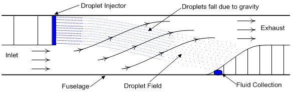
Figure 1. Schematic of a High Altitude Droplet Heat Exchanger System.
3.1.2 Performance/DHX Metrics Summary
Target heat transfer: 50 kW @ 65kft, 50°C supply liquid, air heat capacity of 5.4 kJ/m3, and aircraft speed 80 knots, implying an air heat rejection power capability of 3.67 kW per m2 degree C temperature change.
Basic DHX Design: DHX area of 0.25 m2 (square dimension of 0.5 m), droplet size 0.5mm, droplet field length 2 m, DHX liquid flow rate 0.65 kg/s, ΔT of 55°C in DHX, giving a heat rejection power of 50 kW.
Metrics of a DHX System: (See Section 4.3 for detailed discussion)
1) DHX Mass Metric; kW Heat Rejected per kg mass
Estimated mass of the components of a DHX system: 1) A pressurized fluid reservoir manifold - 1 kg, 2) An oscillating pressure driver that forces uniform droplet generation - 0.5 kg, 3) Droplet field - 0 kg (free falling) 4) A fluid collection and recirculation system - same as standard HX, and 5) Enclosing ductwork - 0.5 kg.
- The DHX Mass per kW rejected metric is estimated to be 0.04 kg/kW
- DHX mass scales linearly with heat rejection power.
2) DHX Drag Metric: For current baseline design, flow force on a droplet = 7.6 x 10⁻⁶ newtons (N); total number of droplets = 8.2 x 10⁵, implying a total drag of the droplets in the DHX = 7.3 N. The duct drag is estimated to be 12 N, and the DHX thrust is estimated to be 14.5 N. The Total Drag is estimated to be about 5 N; extremely low.
- The DHX Drag per kW rejected is estimated to be 0.1 N/kW.
- DHX drag scales linearly with heat rejection power.
Practicality of the DHX system. The cost and ease of fabrication for the system are clearly driven by the need for a low mass design. For the DHX design considered here the cost and fabrication of all components appears practical and for reasonable cost. Critical Issues addressed in a Phase 2 prototype will be low mass design and fabrication, uniform droplet generation and fluid mass loss. Current assessment: not easy, but no major problems.
DHX Fluid Loss. Acceptable. Loss mechanism assessment: 1) Non-ideal orifice shape effects - unimportant with current fabrication techniques, 2) Droplet collision effects - negligible; flow separates droplets, 3) Evaporation - negligible for a 10 hr flight; lower vapor pressure oils can be used for longer duration flights. 4) Satellite droplet losses - negligible for demonstrated uniform droplet generation.
3.1.3 Phase 1 Achievements and Advances
Phase 1 work has resulted in the following achievements:
- Completed an overall DHX design.
- Completed a low mass DHX design.
- Developed a quantitative measure of DHX mass per kW heat rejected.
- Calculated DHX drag.
- Demonstrated that DHX liquid loss will be insignificant for a 90 hr or longer flight.
- Redesigned DHX ducting to minimize drag and be more consistent with aircraft fabrication.
- Developed and demonstrated a low mass, inexpensive means for generating the oscillating pressure required for uniform droplet production.
- Fabricated and demonstrated a DHX liquid jet and droplet generation apparatus.
- Fabricated and demonstrated droplet imaging
- Developed, tested, and used a novel droplet uniformity diagnostic.
- Generated extensive jet and droplet test data
- Wrote numerous MathCAD programs analyzing data.
- Further developed the DHX design MathCAD program.
- Demonstrated that jet/droplet experimental results were totally consistent with work performed elsewhere.
- Physics of jet and droplet experiments fully explained and understood.
- Formed and extensively interacted with a Grumman systems designer concentrating on heat exchangers for the same DARPA program.
- Demonstrated overall feasibility.
The program goal was to demonstrate experimental and design practicality. This has been accomplished. A low mass design has been defined, and an important device component - the oscillating pressure driver - has been developed. Previously this oscillating pressure driver was very expensive and used a significant amount power. A much more practical and novel pressure oscillation driver was conceived, fabricated, and demonstrated, through a concept that can readily be developed in Phase . The overall design has also been greatly refined and verified.
Conclusions: Current work indicates that the concept is even more promising than 1997 study - less stringent altitude requirements, better understanding of design and feasibility issues, and major advances in making a practical, inexpensive, low mass DHX a low mass system. The lower mass and much lower drag of a DHX in the absence of know development problems justifies its further development.
3.1.4 DHX Specification. The baseline specification of the design DHX is as follows:
| DHX area: | 0.25 m2 (square dimension of 0.5 m) |
| DHX length: | 2 m |
| Droplet size: | 0.5mm |
| Liquid flow rate: | 0.65 kg/s |
| DHX ΔT: | 50°C in DHX |
| Heat rejection power: | 50 kW |
| Injector plate: | 1100 precision holes (33 x 33) on the order of 0.5 mm in diameter |
3.1.5 Program Background. The current SBIR Phase 1 program is formed on the foundation of significant previous work. Aside from extensive DHX academic work, the primary relevant background, referenced often, is a major DOE project performed by STI Optronics [5]. This work led to the initial Thoughtventions SBIR project to assess the feasibility of using a DHX for a high altitude aircraft in 1997 [1]. Throughout the work on this program this past work has been reviewed and improvements made on past conceptual design work. No additional problems found. Some feasibility issues have been eased due to a lower baseline altitude, and practical problems appear less severe than previously believed.
4.0 PHASE 1 TASK WORK DETAILS
4.1. Phase 1 Proposal Objectives
The Phase 1 proposal contained the following objectives:
Task 1 - Spray Design & Fabrication
Objectives: Define and describe a conceptual droplet spray and collector system that will generate and capture the droplet field defined in Task 1. Determine the constraints that the spray and collector system place on the choice of fluid. Determine the variability that can be achieved in overall flow parameters to adapt to different heat loads. Determine injection pattern and droplet size and optimize the configuration and parameters for the spray of a UAV droplet heat exchanger operation.
Task 2 - DHX Chamber Design & Fabrication.
Objectives: Design a low pressure chamber that can be used to simulate high altitude heat transfer by a representative DHX spray and fabricate this chamber.
Task 3 - DHX Experiments.
Objectives: Perform DHX experiments to demonstrate heat exchange appropriate to a high altitude aircraft.
Task 4 - High Altitude Aircraft DHX Feasibility/Phase 2 Plan
Objectives: Assess the feasibility of using a DHX in a high altitude aircraft based on experimental work in this project and the modeling and engineering work of the previous project. Define a Phase 2 plan to develop and test a prototype heat exchanger system.
4.2 DHX Design and Design Advances
It is comparatively easy for a DHX to reject 50 kW of heat to the air at 65,000 feet. The MathCAD program written during the previous Phase 1 program has been extensively updated and modified for the current project. At this altitude the temperature of the atmosphere is approximately -56°C (217 K). The DARPA target low quality heat rejection temperature is approximately 320 K, so a ΔT of about 50 C is reasonable for an increase in air temperature after passing through the DHX. The air density at altitude and the specific heat of air implies an air heat capacity of 5.4 kJ/m3. Assuming an aircraft speed of 80 knots, the gas flow speed through the DHX is 41 m/s, which implies an air heat rejection power capability of 220 kW/m2, and thus a required DHX area of about 0.25 m2 (square dimension of 0.5 m) would provide a heat rejection power of approximately 55 kW, which is the target power rejection capability.
For this design, the air mass flow rate through a 0.25 m2 aperture is 0.9 kg/s. An approximate DHX design condition is that the thermal mass flow rate (specific heat x mass flow rate) of the air matches that of the droplets. This implies a significantly lower droplet mass flow rate, since the specific heat, cp, of air is 0.24 cal/g-K, whereas the specific heat of the low vapor pressure oil used as the DHX fluid is 0.33 cal/g-K, so the required liquid flow rate of droplet fluid is 0.65 kg/s.
DHX Design. There are upper and lower limits on the droplet size for any DHX. Droplets that are too large break up as a result of gas shear, whereas very small droplets (microns) are carried away by the air stream and lost from the heat exchanger. There is also a practical fabrication limit to achieving a small droplet size; the heat ultimate exchange capacity is determined by the total droplet mass, so for very small droplets, the number of injection orifices becomes too large to be practically fabricated. In the case of a high altitude DHX there is a significant range of stable droplet sizes that can be used - at least an order of magnitude - diameters from 0.1 mm to 1.0 mm.
Design of the droplet field is the dominant aspect of a DHX design. The droplet field of a DHX is defined by the droplet size, the droplet velocity, the three dimensional spacing between droplets, the cross sectional area of the field in the direction of the flow, and the length of the droplet field.
For the purposes of DHX fabrication design, these are all dependent parameters. The droplet size is determined primarily by the DHX injector hole size. The droplet velocity is determined by a combination of the hole size, the pressure driving the jet through the orifice, and the properties of the fluid. The three dimensional spacing of the droplets is determined, in the direction of motion, by the hole size (the axial spacing is determined by the droplet size), and, normal to this axis, by the spacing between the holes. The cross sectional area of the DHX is determined by the rejected heat power required that determines the necessary air mass flow rate, given an air temperature rise. The length of the droplet field is determined by practical length constraints and the length required for adequate heat exchange between the air and the droplets.
One can readily conclude that optimizing the DHX design for a specific application is very complex. A design schematic is shown in Figure 2. Arrows indicate the design flow, and Pr, the rejected heat power, is the goal of the design. To transfer the maximum amount of heat to the air, the DHX mass flow would be much larger than the air mass flow, but this would not lead to a low mass system, so to first order the liquid and gas mass flow rates are set equal.
It is instructive for the purposes of understanding DHX design (and for understanding its difficulty) to approach the problem of DHX design from a number of directions.
The gas/droplet heat transfer is described in terms of the local Nusselt number, Nu = hd/kg, where h is the local coefficient of convective heat transfer, d is the droplet diameter, and kg is the gas coefficient of thermal conductivity. The convective heat transfer in a cloud of droplets results from the thermal energy interaction between the droplets and the flow field around the droplets, which is in turn affected by the global and local droplet field. For this reason an empirical relationship for Nuave is used that accounts for both the flow regime (determined by the Reynolds Number, Re, and the volumetric concentration, β, of evenly spaced droplets. For the ranges of 0.00035 < β < 0.0025 and 180 < Re < 1800 that are typical of DHX operation [2],
Nuave = 0.0036 β4.8Re0.77
The droplet volumetric concentration is
β = (Nd)(πd3/6)
where Nd is the number of droplets per unit volume, which is in turn determined by the number of droplet injection holes per unit area and the droplet spacing.
Although the density of droplets in the DHX controls the instantaneous local heat transfer rate, the overall power rejection capability for a DHX depends on the frontal area of the droplet field and the mass flow of droplets. It depends on the length of the DHX to a lesser extent, since the length controls the completeness of the heat transfer, and for normal DHXs L/Ds of 4 are typical, and longer DHXs are not justified due to the diminishing heat transfer returns for added length.
The heat rejection power, P, of the DHX assuming a droplet field area, volume fraction, speed and temperature loss by the liquid is P = cplΔTl(dml/dt) where ΔTl is the temperature difference of the liquid, cpl is the specific heat of the liquid, and the liquid mass flow, dml/dt, is dml/dt = AβρlUl where A is the area of the droplet field, ρl is the liquid density, and Ul is the liquid velocity. Note the direct dependence of heat transfer power on mass flow, which is determined by the number of droplet orifices, their diameter, and the fluid injection speed. The heat power rejection capability is then
P = cplΔTAβρlUl.
The mass flow of droplets is also determined by the total area of the droplet field, its mass fraction, and the density and velocity of the liquid drops. The other parameter determining the heat transferred between the liquid and gas is the temperature difference that is achieved between the inlet and exit of the DHX. The droplets cool as they pass through the airstream before they are collected and recirculated, while the gas is heated and flows back into the atmosphere. The temperature gradient for the liquid is [3]
dTl/dx = - (6Nudkg/ρlUlcpldl2)(Tl - Tg)
and the corresponding gradient in the gas
dTg/dx = - (6Nudkgβ/ρgUgcpgd2)(Tl - Tg)
where T is the temperature of the liquid (l) and gas (g), Nud is the Nusselt # of the droplet, and kg is the thermal conductivity of the gas. The droplet Nusselt number in turn, is given by
Nud = 2 + 0.74Pr1/3Red1/2
where Pr is the Prandtl number (0.7 for air), and Red is the droplet Reynolds number, ρgUldl/µg, and µg is the gas viscosity.
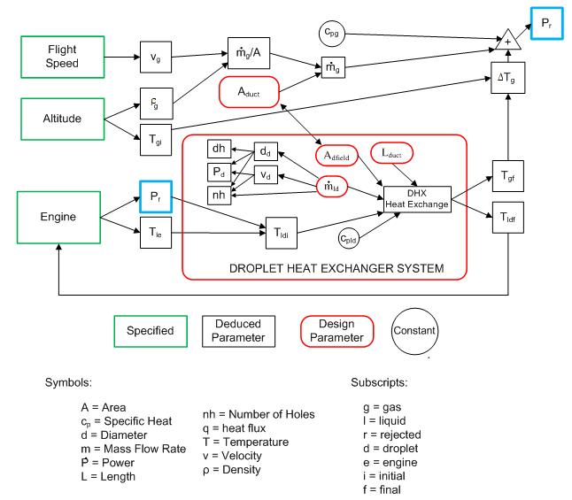
Figure 2. DHX design process schematic.
From yet another perspective, the heat exchanger effectiveness (ratio of actual to ideal heat exchange) increases as droplet size decreases, for a specific DHX length. However, for a fixed total heat transfer rate, if the droplet diameter, d, is decreased, the number of required droplet streams increases proportional to 1/d2. The mass for each droplet mass is proportion to d3, while drag force is proportional to d1/2 and Ur1/2. Thus, one could decrease the droplet size to increase the effectiveness of the DHX, but at the fabrication expense of a significantly larger number of injection orifices. Increasing droplet diameter decreases the DHX effectiveness, but lessens the overall drag of the DHX as a result of much fewer droplets.
Previous work has indicated that a DHX adapted for high altitude heat exchange would use a droplet size of about 0.5 mm, which is the design droplet size studied in this program.
4.3 DHX Drag and Mass Metrics
System design for DHX minimum mass/drag. Much of the design of a low mass DHX is concerned with the design of low mass structures rather than minimizing mass per cooling frontal area as in standard heat exchangers. There are two basic types of low mass volume containment structures - self supporting walls and boundary supported films. In the case of a DHX, the structures must support either air (the DHX airflow duct) or liquid pressure differences across the walls (the DHX spray manifold and plumbing). Air pressure differences in the DHX duct can be small, leading to the possibility of very low mass structures that provide a duct area boundary. Liquid containment requires stronger materials, but the liquid boundaries are those that can allow much better load distribution over the surface - cylindrical pipes can be very thin walled. Progress in the area of light weight structural materials has, as usual, not been uniform. The basic concept of a honeycomb structure has remained the same, while the mass specific strength of materials has been steadily increasing, thanks to advances in composites and nanomaterials.
Developing these metrics in detail is beyond the scope of the Phase 1 effort because of the complexity of the structural designs, the variety of available materials, and the fact that all previous work on DHXs has not even considered either low mass fabrication or overall drag. This section of the Report details and justifies the results presented in Section 3.1.2.
4.3.1. DHX Mass Metric. A DHX system (Figure 1) consists of the following fundamental components:
- The droplet injection system consisting of:
1a) A liquid injection manifold
1b) The liquid contained in the manifold.
1c) An oscillating pressure driver to make uniform droplets - The droplet field
- The ductwork containing the DHX flow
- The liquid collection system
- The liquid recirculation system
5a) plumbing
5b) liquid pump - 6) Fluid reserves
The DHX differs from a standard plate and fin heat exchanger in requiring an injection system. It is assumed that the liquid of the DHX is the primary cooling liquid of the aircraft. The DHX and standard heat exchangers have air ductwork in common, as well as a liquid recirculation system, although the liquid recirculation system of a DHX involves longer pipes. In the analysis below it must be kept in mind that a DHX system has never before been built with the goal of low mass.
1) Low Mass DHX Manifold Design. The design droplet field injection base area of the DHX for a 50 kW heat transfer capability is approximately 0.5 m x 0.5 m. This is the area over which droplets must be injected, and thus this is the size of injector plate containing many holes with a fluid reservoir behind all of the holes. The injector plate must be flat to keep the droplet flow parallel.
The constraints on the manifold design are that it withstand an internal pressure on the order of 1 atm, and that the flow passages to the many droplet orifices have a pressure drop that is small compared with the driving pressure. These constraints also satisfy the requirement that the manifold be robust enough for handling, installation, and that it be consistent with the fact that it is a part of the aircraft.
The minimum mass design goal of the manifold and its supply is to optimize the balance between greater liquid thickness (more liquid mass) and the number of supply points (tubes) (supply plumbing mass and liquid mass in the supply tubing) to the area. A typical distribution system is shown in Figure 3. The volume flow rate is about 650 cm3/s over the entire injector plate area. The flow average per unit area (0.25 m2) is 2.6 cm3/s per cm2 of injector area. Assuming a maximum permissible local fluid velocity of 1 m/s, a flared 10 cm single central feed of liquid, and uniform thickness of the manifold, then the 31.4 cm diameter, x thick cylinder must feed the rest of the plate. The required liquid thickness would be (100 cm/s)(31 cm)(x cm) = 650 cm3/s, so x would be 0.2 cm.
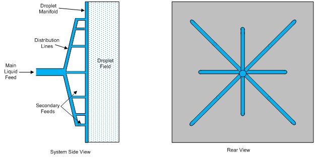
Figure 3. Droplet manifold and supply system schematic.
This indicates that the manifold liquid supply can be very thin, and that the dominant mass of the manifold is not the liquid, but the mechanical structure. Probably 8 feeds spaced from the injector center as shown in Fig. 3 would be optimal. For a liquid density of 1 g/cm3, a 0.2 cm thick liquid layer in a 0.5 m x 0.5 m manifold would have a mass of (1)(50)(50)(0.2) g = 0.5 kg.
An important mass advantage of a DHX over a standard HX is that there is no need for metal - much lighter materials can be used. Injector plates have been made out of steel in the past, which is much too heavy for this application. Plastic or composites are the most attractive candidates, with specific gravity close to 1. An obvious possibility is to use the front face of some type of plastic honeycomb material. The honeycomb material would have distributed small column supports rather than closed cells. Internet searches have shown that such a material is not in common use, but there seems to be no problem in making this material. The injector plate face must be thick enough to provide the orifices needed for uniform droplets. For the present design case this is not an issue. For an L/D of 2 hole with 100 µm diameter orifices, the plate only need to be 0.02 mm thick. It will be considerably thicker than this, so making the L/D larger is a natural option. An L/D of 5 would remove the necessity for a rounded intake and allow easier fabrication of the plate.
Taking as an example plastic honeycomb material with a 0.5 mm thick orifice sheet on one side would have a mass of about 1.5 kg/m2 (see the shell material mass discussion below). The injector plate would then have a mass of (1.5 kg/m2)(0.25 m2), or about 0.37 kg. To this would be added the mass for the fluid manifold structure and the mass of the fluid itself, totaling something on the order of 1 kg. The injector plate must also have adequate stiffness to maintain the pointing of the orifices, but the sample obtained during the previous project were stiff enough.
1c) Oscillating Pressure Driver. to make uniform droplets. Program research has shown that a high speed, low power electric motor can be used to generate the oscillating pressure. Such an apparatus will weigh at most 0.5 kg.
2) Droplet Field Mass For this design, the air mass flow rate through a 0.25 m2 aperture is 0.9 kg/s. An approximate DHX design condition is that the thermal mass flow rate (specific heat x mass flow rate) of the air matches that of the droplets. This implies a significantly lower droplet mass flow rate, since the specific heat, cp, of air is 0.24 cal/g-K, whereas the specific heat of low vapor pressure oil is 0.33 cal/g-K, so the required liquid flow rate of droplet fluid is 0.65 kg/s. For a 0.65 kg/s mass flow, a 20 m/s average droplet velocity (droplets accelerated by the flow), and a DHX length of 2 m, the droplet residence time is 0.1 s, and the droplet field mass in the DHX at any instant is approximately 0.065 kg. Furthermore this mass is free falling and thus adds zero mass to the aircraft during flight.
3) DHX Shell Mass. The proposed DHX box is 0.5 x 0.5 x 2 m long, with a surface area of approximately 5 m2, not including shaped inlet and exhausts, which are common to both types of heat exchangers.
The key to fabricating a low mass DHX box is the realization that the sides need not be rigid. In this case one can design the walls to be made of strong, thin film material. This type of material is commonly used to make high altitude balloons, and is a tri-laminate [4] plastic. The mass of this material varies between 25 and 40 g/m2, so to cover the 5 m2 area requires a mass of only about 150 g. Additional mass will be required to establish the duct corners and reinforce the appropriate sides, but this mass is not as area dependent. A conservative estimate on overall box mass would be approximately 0.5 kg.
4) Collector. The FLUENT calculations show that the droplet field will impact on a fairly small area at the bottom end of the DHX box. The droplets will impact the wall, form a liquid film, and the liquid film will flow by gravity into a reservoir. The reservoir fluid can be then be pumped by the recirculation system. The reservoir will be sloped in both dimensions to promote rapid flow and minimum volume.
5) Fluid Recirculation system. The fluid recirculation system of the aircraft consists of the pump(s?) and piping required to move the cooling liquid throughout the cooling system. The DHX is the part of the system that rejects system heat to the surrounding air. The cooled fluid gathered from the collection port at the end of the droplet section of the duct must be transported to the heat sources and then back to the injection manifold where the cooling droplet field is collected.
The question addressed in this subtopic is the amount of mass added to the system due to the DHX. The proposed system needs to move 0.65 kg/s of specific gravity 1, modest viscosity fluid. This is a volume flow rate of about 40 liters/minute, a normal flow rate for a cooling system. Since the DHX has no pool that would require extra mass except in injection manifold and supply one would not expect significant extra liquid mass in the recirculation system. The DHX will probably require extra pumping power, but the extra mass of the additional motor power required should be small.
It should be noted that using advanced pump motors can provide significant system mass savings. Advanced motor designs (although not designed for minimum mass) provide an energy density of 2 hp/lb. Thus a 1/2 hp motor would have a mass of about 0.1 kg.
Overall Mass per kW Rejected Metric. Summing the above component masses gives a total DHX mass of less than 2 kg, significantly less than a comparable plate and fin HX. The heat power rejected for this mass DHX is 50kW, so the DHX Mass per kW rejected metric would be 0.04 kg/kW. The mass of the DHX should scale linearly with rejected power.
6) Fluid Loss from the DHX for Long Duration Flight. Associated with the question of DHX system mass is the question of how much mass is added to the system by the requirement of carrying additional DHX liquid as a reserve to replace fluid loss during a flight. A DHX is necessarily an open system. Warm liquid droplets are injected into a colder air stream. The droplets move downstream relative to the aircraft but much more slowly than the air flowing through the duct. After passing through the co-flowing volume, the liquid is collected and recirculated while the gas, heated by the droplets, passes out of the DHX. The heat source, the DHX design, and properties of the gas define the temperature difference between the media.
For the current project, long duration heat exchange is a requirement for the heat exchanger. The duration may be a day or many days. It is thus critical that the operation of the heat exchanger not degrade significantly over this period. In the specific case of a DHX, droplet fluid lost to the airstream is a potential problem, either in terms of duration limitation or reserve liquid mass requirements. Estimation of fluid loss has thus been an important task for Phase 1 work.
There are a number of non-ideal spray processes that might contribute to fluid losses. These can be categorized (not in order of importance) as 1) Non-ideal orifice shape effects, 2) Droplet collision effects, 3) Evaporation, and 4) Satellite droplet production. The injectors are designed so that 100% of the droplet trajectories remain in the DHX. Furthermore, normal turbulent fluctuations are not sufficient to move droplets of design size out the exhaust.
Non-ideal orifice shape effects. The most easily controlled aspect of the droplet spray process is the amount of transverse velocity that the droplets possess after they emerge from the spray orifices. The transverse velocity must be small enough so that no droplet can pass out of the DHX without hitting the collector wall. Current fabrication techniques are accurate enough so that improper hole angles that arise from aberrant holes can simply be identified and sealed off. The length to diameter ratio of the holes is such that transverse velocity fluctuations arising from the injection process are small compared with that needed for droplet escape.
Droplet Collision Effects. Droplet collisions are minimized by the fact that the flow around the droplets tends to separate them when they approach each other; a decreased distance increases flow resistance between the drops, decreasing flow speed and increasing flow pressure, driving the droplets apart. Since the droplets are all at similar speeds, any collisions that do occur tend to be coalescences. Splash from droplet impact on the collector surfaces should be unimportant because of the low mass of the droplets. To reach the exhaust, splash droplets must also penetrate the boundary layer next to the plate; otherwise the droplets will be captured by the lip at the exhaust section.
Evaporation. Evaporation fluid loss is minimized by using a low vapor pressure fluid and relying on droplet cooling to further lower evaporation. Since evaporation rate is a strong function of temperature, only the initially warm fluid undergoes significant evaporation. Assuming the design value of 0.5 mm diameter droplets, the volume of each drop is 6.5 x 10⁻¹¹ m3, the mass of each drop is 7 x 10⁻⁸ kg, and the surface area of a drop 7.5 x 10⁻⁷ m2. Thus there are 5.7 x 10⁵ drops in the field with a total surface area of 0.43 m2. Note the large surface area, although this is small compared with the surface area of a plate and fin radiator. One constraint for insignificant fluid mass loss through evaporation is that the evaporation mass flow over a 10 hour period be insignificant compared with the fluid mass in the system.
The rate of oil evaporation, R, has been calculated based on experimentally established kinetic theory. The evaporation rate from silicone oil with a molecular weight, Mso, with a vapor pressure pmm (in millimeters Hg) at a surface at temperature Tso (Kelvins) is [6]:
mR = 10-4.23(Mo)(103)(pmm)(Tso)-0.5 g/cm2-s
For Dow Corning 704 silicone vacuum oil, Mso = 484, and at Tso = 323 K (50°C manifold oil temperature), Pmm = 6 x 10⁻⁷ torr. Thus R = 4.35 x 10⁻⁸ g/cm2-s. About a fifth of the droplet field would be near 50, since the droplets cool rapidly and the vapor pressure decreases rapidly with liquid temperature. For a period of 10 hours (3.6 x 10⁴ s) and a surface area of 4.3 x 103 cm2, the mass loss would then be calculated to be approximately 2 g. This is an insignificant amount, and it means that a higher vapor pressure (and lower viscosity, which is a much easier liquid to use) can be used as the DHX liquid. Silicone oils are commercially fabricated (Clearco, PA) to have an arbitrary molecular weight and vapor pressure at temperature, although they are not fabricated with this in mind. The specific oil used for the DHX would depend on the flight duration and the acceptable mass of the liquid reserve tank. The above calculation was verified using known evaporation data and confirmed by independent estimation methods.
Satellite droplet production. Another major possible fluid loss mechanism is the generation of small satellite droplets that can be carried out of the DHX by the airstream. Droplets smaller than the nominal size can be generated by a variety of processes. The number and size of these satellite droplets in a real DHX would determine the total fluid loss due to this cause. Production of satellite droplets is common in unexcited spray creation. As the liquid jet column becomes unstable and surface tension forces neck the column down, all of the fluid is not able to be drawn into the nominally sized droplet and forms independent, smaller sized satellite droplets between the larger droplets. The satellite droplets are of a size that follows the flow much more than the nominally sized droplets, so that they are much more likely to be lost from the DHX when the gas flow exits. These satellite droplets contain much less mass than the nominally sized droplets. A satellite droplet with a diameter 1/4 of the nominal size will only have 1/64 of the mass of a standard droplet, but as has been described above, only very small mass losses are tolerated in this application. The primary detrimental effect of droplet collisions with surfaces will also be in the production of small droplets.
Extensive work has been done on uniform droplet generation, including a great deal of experimental work. Theory and experiments show that practical devices make 100 % uniform droplets without satellites. Non-ideal processes cannot be ruled out, however, so the remaining mechanism for droplet loss is that smaller droplets that would be carried out of the DHX by the flow might be generated at some location in the DHX.
Based on work at STI on the generation of uniform droplet fields, it can be stated that using their technology, satellite formation almost undetectable; in the range of very small fractions of a percent. Using a photodiode to measure droplet sizes being generated by an orifice, data showed that silicone drops could be made essentially free of satellites or nonuniform drops by applying a sufficiently large vibration signal. The vibration amplitude required to eliminate nonuniformity (≈ 990 pa or 0.24 psi) was much larger than that which caused transition from random to regular breakup (≈60 Pa or 9 x 10⁻³ psi at this test condition) for the silicone fluid. A reduction in vibration amplitude by approximately 20 percent generally resulted in more than 5 percent of the drops having satellites or nonuniform diameter. Further reduction in vibration amplitude would result in increasing numbers of satellites and nonuniform drops, but the main drops formed very regularly at the excitation frequency. This characteristic of the lower viscosity (silicone oil) tests was markedly different from the variation in jet breakup with vibration amplitude observed with the high viscosity fluid (glycerin water).
The flow field of the DHX tends to trap smaller droplets, due to the is a recirculation zone at the upstream end of the DHX next to the injector plate. FLUENT calculations indicate that all small droplets emerging from any location on the injector get get preferentially swept into the recirculation zone.
Another significant aspect of the current application is the low air density - 10% of surface density. This means that only droplets a factor of 10 smaller than usually considered will be carried out of the DHX. At altitude only much smaller and much, much smaller mass droplets might be carried out of the DHX. The lower air density also implies a much lower probability of formation. This implies that the satellite droplet loss problem will be greatly reduced for this application.
It is concluded that mass loss of the fluid will not be significant except possibly for very long term operation.
Liquid/Liquid Heat Exchanger. At the beginning of the program it was assumed that the DHX would be an add-on or a retrofit to the high altitude aircraft. Later, in response to mass concerns of the added mass of this component, Andrew Carl of Grumman commented that the engine for the proposed DARPA had not yet been designed, which meant that the engine could be designed with somewhat larger liquid passages consistent with the required DHX liquid.
Before that it was assumed that the DHX would employ a liquid/liquid heat exchanger to exchange heat between the engine water/antifreeze liquid and the DHX silicone oil. Thus in order to determine the overall mass of the DHX system, the mass of the liquid/liquid heat exchanger would have to be estimated, which necessitated the design of an appropriate plate and fin liquid heat exchanger. Initial calculations showed this to be a difficult task for a 50 kW heat exchanger.
A MathCAD program, DHX Liquid-Liquid Heat Exchanger.xmcd was written to simulate the effectiveness and calculate the mass of a 50 kW multi-plate water-oil heat exchanger. The outputs include temperature profiles of all liquid flows, total heat exchanged, fluid pressure drops and heat exchanger mass. The design began with a single pass double sandwich plate heat exchanger, where there were 3 plates (one was the injector plate) with water flow between the rear plates, and oil between the front plates. Calculations showed that the heat transfer was not enough in this design. To increase the heat transfer, cross plates were added (Figure 4) to transfer heat to the injector plate. This was still not enough. We finally had to postulate a sandwich of 2 water passages and 3 oil passages as indicated in Figure 5.
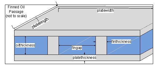
Figure 4. Schematic of a single layer of the liquid/liquid heat exchanger.
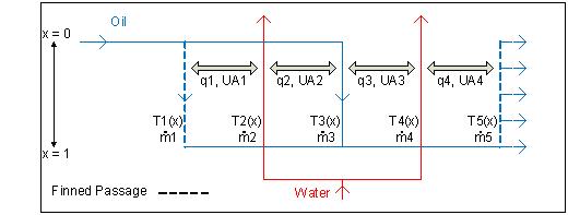
Figure 5. Schematic of the heat exchange in a triple layer liquid/liquid heat exchanger.
| platewidth = 0.5 meters | Width of Central (Dividing) Plates |
| platewidth = 0.5 meters | Length of Central (Dividing) Plates |
| platethickness = 0.001 meters | Thickness of Central (Dividing) Plates |
| finthickness = 0.002 meters | Thickness of the fins connecting plates on either side of the oil channel (used only when one of the two plates would not normally be involved in heat exchange, i.e. the ends of the heat exchanger) |
| oilthickness = 0.0015 meters | Separation between the plates for the oil passages |
| waterthickness = 0.001 meters | Separation between the plates for the water passages |
| fingap = 0.02 - finthickness meters | Distance between the edges of the fins in the oil passages (when used); equal by definition to the channel width of oil flowing through |
| finwidth = platelength meters | The fins span the length of the plate |
| finlength = oilthickness meters | The fins connect the plates on either side of the oil passage |
| kplate = 200 W/m-K | Plate Thermal Conductivity |
| oil = 55 x 10-6 m2/s | Oil Kinematic Viscosity |
| oil = 103 kg/m3 | Oil Density |
| koil = 0.169 W/m-K | Oil Thermal Conductivity |
| cpoil = 2 x 10³ J/kg-K | Oil Specific Heat Capacity |
| cool = 1 x 10⁻⁶ m2 | Coolant Kinematic Viscosity |
| cool = 103 kg/m3 | Coolant Density |
| kcool = 0.6 W/m-K | Coolant Thermal Conductivity |
| cpcool = 4 x 10³ J/kg-K | Coolant Specific Heat Capacity |
| Tinoil = -30°C | Oil Inlet Temperature |
| mflowoil = 0.5 kg/s | Total Oil Flowrate |
| Tincool = 50°C | Coolant Inlet Temperature |
| mflowcool = 0.5 kg/s | Total Coolant Flowrate |
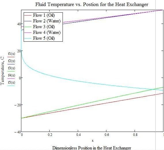
Figure 6. Temperature profiles in the liquid/liquid heat exchanger design.
The temperature gradients found in the heat exchanger are shown in Figure 6. The mass of this heat exchanger was then calculated, including the liquid between the plates. This mass was calculated to be 5.7 kg, which would mostly negate the mass advantage of the DHX.
Since this is an oil/water heat exchanger, one can design a much lower mass direct contact heat exchanger since water and oil are immiscible. Probably some dopant would be added to the oil to increase its density so that it could be mixed with the water and then centrifuged out. However, this is a development project in itself.
4.3.2 DHX Drag Metric. The drag coefficient for a single spherical droplet is [5]:
cD = (24/Red)[1 + 0.15Red0.687] + (0.42)/(1 + 4.25 x 10⁴Red-1.15)
for Red < 3 x 10⁵. For the present design of a 0.5 mm diameter droplet in high altitude air with a relative velocity of about 20 m/s, Red is on the order of 100, and the drag coefficient is about 1. The force on the droplet is then on the order of 10-5 newtons (N). MathCAD calculations give a droplet Reynolds number = 92, a droplet drag coefficient, CD = 1.1, and a drag force on each droplet = 8.8 x 10⁻⁶. For the designed DHX there are approximately 8.3 x 10⁵ droplets in the flow, resulting in a total drag = 7.3 N.
The overall drag of the DHX would be the total of the droplet drag, the duct drag, and the thrust of the DHX (the exiting gas is heated and therefore has a higher exhaust than inlet velocity). Using MathCAD calculations again, the Reynolds number based on the duct diameter is 1.2 x 10⁵. The pressure difference due to flow down the duct is:
Δp = (f)(4)(Leff)(ρg)(vg2)/2(Dduct)
where f is the friction factor; f = 0.01, Leff is the effective length of the duct (Leff = 10 m), vg is the gas velocity (vg = 41 m/s), and Dduct is the duct diameter (Dduct = 0.5 m). The Δp = 60 N/m2, and the drag on the 0.25 m2 area duct = 12 N.
The thrust of the DHX is assumed to be equal to the air mass flow rate, 0.72 kg/s times the air Δvg. For a gas temperature change of 55°C, the exhaust velocity is calculated to be 100 m/s, and thus the thrust is calculated to be about 14.5 N.
The metric of drag per kW would then be approximately 0.1 N/kW.
The final question to be answered is how the DHX drag scales with heat rejection power. For the same droplet diameter the heat rejection power scales like the mass flow - the thermal heat capacity rate of the liquid. The drag is proportional to the number of droplets in the flow - roughly the total liquid mass. Thus one would expect the drag of the DHX to scale linearly with the heat rejection power.
4.4 DHX Laboratory Experiments
Experimental work is discussed primarily in the sequence in which it was performed. The goal of Phase 1 experimental work was to demonstrate appropriate uniform droplet generation in a manner suitable for use in a high altitude aircraft and derive a practical, cost effective initial engineering design of a DHX from this work.
4.4.1. Initial Apparatus Design. Phase 1 work began with the design of a Spray Test Apparatus. The objective of this apparatus was to provide a liquid jet or jets that would break up into uniform droplets in response to an oscillating driving pressure. The jet and the droplets formed from it would then be measured for uniformity.
Spray Apparatus Design. The spray apparatus design is conceptually simple - a pressurized reservoir of liquid feeds an orifice out of which emerges a liquid jet that breaks up into droplets downstream. Design and fabrication complications arise from the requirement for low pressure oscillations superimposed on the average reservoir pressure. These pressure oscillations force the jet to break up into uniform droplets without significant size dispersion. Creation of the proper liquid jet requires significant care.
It is necessary to use precision orifices to create the liquid jet, so that the droplet size is reproducible from design parameters and provides essentially identical droplet streams when using the multiple holes of a DHX. For the Phase 1 project high precision orifices were purchased and installed in the bottom plate of the chamber. A Bird Precision (Waltham, MA) Orifice # 22098 was used for initial experiments. This is a precision sapphire orifice that is 0.38 mm (0.015") in diameter and 0.66 mm (0.026"), long built into a 6-32 screw for easy incorporating into the apparatus. Other orifice sizes were obtained as well, to explore orifice diameter change effects. The orifice shape and diameter is highly accurate, with tolerances that are small compared with the diameter. Phase 1 work began with a single orifice, with the option of inserting more or different orifices.
Initial Droplet Test Apparatus. The initial droplet test apparatus consisted of a spray generation chamber, together with its ancillary equipment (pressure supplies and sensors, vacuum pumping and sensors, oil feed, plumbing, mounting apparatus, etc.) and the droplet imaging system.
The reservoir chamber was made out of a Thoughtventions Unlimited surplus vacuum chamber. Using a vacuum chamber has many advantages - standard flanges, a clean environment, and multiple access ports to the internal volume. The side ports were used for optical access and feedthrus for gas, oil feed, and electrical connections. The top of the chamber was used to mount a pressure oscillation driver motor, and the orifice was mounted in the bottom plate. A downward vertical jet orientation was chosen to avoid changes in jet direction caused by gravity.
The pressure oscillations needed for uniform droplet generation consists of a small amplitude sine wave superimposed on an average jet driving pressure, so the reservoir chamber operating at the average pressure had to enclose the device used to provide the superimposed pressure oscillations. Previous work at STI Optronics used piezoelectric drivers for this purpose. These, however, are expensive, require quite a bit of power, and require complex electronics, and use high voltages. From a previous project, Thoughtventions had a resonant electrodynamic driver (Model: 1S102D QDrive, Troy, NY) that is designed and used to generate high intensity sound waves. This driver simply requires a sine wave electrical input and can be driven at 60 Hz from voltages supplied by a variac. It was rated to operate at variable frequency up to frequencies higher than that required for uniform droplet formation. It was initially not clear what exact frequency and pressure amplitude would be required, but it was clear that both of these parameters should be minimized for the most practical DHX aircraft device. It would also be most convenient electronically if the driving frequency could be a 60 Hz multiple. The electrodynamic driver could provide the variability in both pressure oscillation amplitude and frequency - both parameters that needed to be tested later in the program. Since the driver is designed to force a sealed diaphragm to oscillate, the resulting pressure oscillation amplitude could be changed both by changing the voltage to the driver and by changing the air volume in the chamber.
The chamber was sized both to be able to hold a sizable quantity of oil, and to provide an appropriate diameter for mounting and operating the pressure oscillation driver; the chamber diameter was an optimization for the existing driver. Too large a diameter would require a diaphragm that was either too massive or not rigid enough to be driven at frequencies of 240 Hz. The driver amplitude was fixed, so too small a diameter would not provide sufficient oscillating pressure amplitude because the oscillating volume change would be too small. Modeling calculations indicated that a 15 cm diameter would provide large enough pressure oscillations. Whether the designed and fabricated diaphragm was rigid enough with low enough mass had to be determined by experiments - the required driving frequency for uniform droplet formation had to be low enough to be consistent with the mass and stiffness of the diaphragm that was used. The driver assembly is shown in Figure 7. Note the vibration isolation at the bottom of the driver mounting rods. The assembly is show upside down; the top plate of the chamber is on the bottom of the image. The motor is mounted on a plate supported by 4 rods and drives the diaphragm at the top of the image that is sealed with a black O-ring.
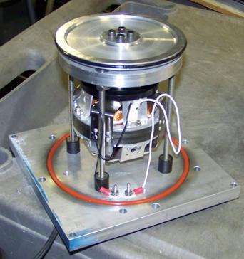
Figure 7. Image of electrodynamic driver and pressure oscillation sealing diaphragm.
One of the drawbacks of using a vacuum chamber as the pressure reservoir in this application is that the chamber wall is rolled and welded. This means that it is not round enough for good circular O-ring sealing, and that there is a weld seam that also prevents a good moving seal. For this reason a sealing ring for the diaphragm was mounted in the chamber as shown in Figure 8.
After fabricating the mount and sealing ring for the oscillator motor and diaphragm, a number of iterations on the diaphragm design were necessary, guided by experiments to determine whether the fabricated diaphragm was adequate. The diaphragm had to be light enough to be able to be driven by the motor, yet it had to seal against the internal ring to be able to generate the oscillating pressure in the lower chamber that was necessary to drive the formation of uniform droplets. This turned out to be a very unusual seal design, where the O-ring was barely touching the sealing ring. Fortunately, thanks to the use of oil as the droplet liquid, lubricating the O-ring was not a problem. Tests showed that the motor could drive the diaphragm full amplitude at 60 Hz. It was expected that further development work would be necessary to make the system work at the higher frequencies necessary to obtain uniform droplets.
The final aspect of chamber design was pressure instrumentation. The average driving pressure was monitored by a pressure gauge. The oscillating pressure was measured by an IC differential pressure sensor (Motorola MPXV5004C), mounted on the sealing ring with its connecting wires penetrating the gas side port. The atmosphere port on the chip was sealed to the sealing ring with a small O-ring, with a hole under this seal that penetrated the ring to the volume behind the diaphragm, allowing the chip to measure only the real time differential pressure (the oscillating pressure) between the two chambers (separated by the moving diaphragm), which is the critical parameter for a uniform droplet generator. The frequency response of this sensor is good enough for this application. More common acoustic pressure sensors are extremely expensive and impractical for purchase for a Phase 1 project.
Figure 9 shows a schematic of the completed initial Phase 1 experimental system. The system centered on the pressurized chamber driving the single jet into a study volume, and contained the electromagnetic driver above the sealed diaphragm plate. A gas line containing a needle valve provided average pressure equalization between the top and bottom sections of the chamber while not transmitting the oscillating pressure. The chamber is supplied with separate, valved lines for evacuation, pressurization, and an oil feed into the chamber. The chamber is o-ring sealed and vacuum leak tight. Oil is quickly drawn into the chamber from an external reservoir when the chamber is under vacuum. Once the chamber is sealed, it is pressurized and the jet orifice is unblocked, resulting in a well formed jet of oil descending vertically from the orifice in the bottom plate of the chamber.
Figure 10 gives an annotated image of the system as it was initially operated. The chamber was mounted to be able to adjust its location vertically and horizontally. The imaging system (described below) consisted of a mirror-enclosed flash lamp and the microscope that could also be moved vertically so that a wide variation in downstream L/D of the jet could be examined.
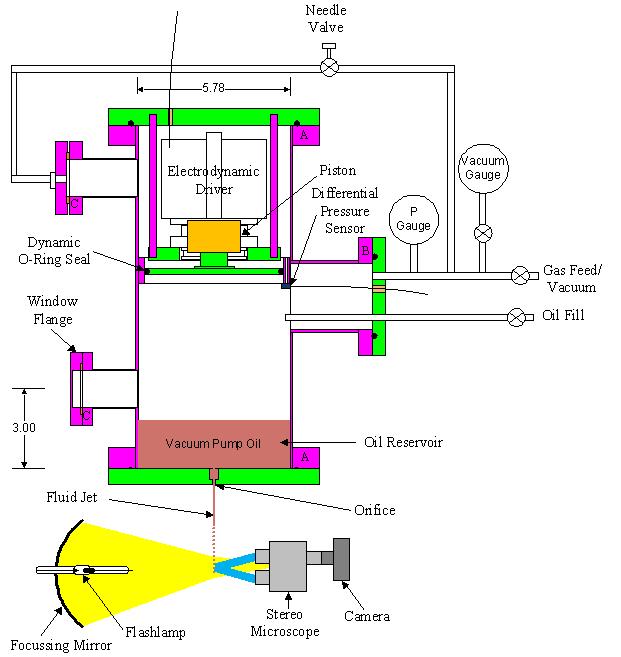
Figure 9. Schematic of the Phase 1 droplet generator and imaging system.
Droplet Imaging System. The droplet imaging system consisted of an illumination system and an imaging system. The illumination system consists of a compact arc flashlamp (as opposed to the more standard linear flash lamp) mounted at the center of an elliptical mirror, together with the flashlamp's supporting electrical apparatus. The imaging system consists of a stereo microscope coupled to a digital camera. This apparatus was adapted from equipment used by Thoughtventions on previous projects.
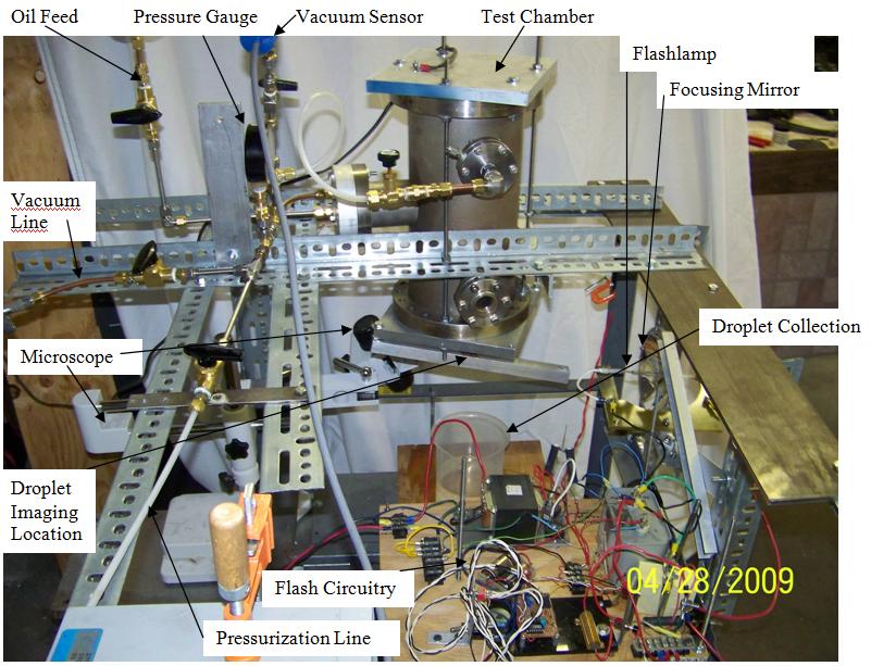
Figure 10. Image of the initial Phase 1 droplet generator system.
The illumination system is designed to be able to focus the maximum amount of short pulselength light onto the field of view of the microscope. A compact arc flashlamp is far superior to a linear flash lamp because the much shorter arc length (5 mm vs 75 mm) allows a much greater fraction of the flash light energy to be focused into a relatively small area. This lowers the flash energy requirement for instantaneous images and makes the electrical supply much more practical. An elliptical mirror (Optiforms, Temecula, CA) allows a large light solid angle to be captured and focused, further enhancing the energy efficiency of the apparatus.
Accurately adjustable mounting of the optics is very expensive. The optical parameters of the mirror are fixed, so it must be mounted with its aperture plane normal to the axis between the target center and the mirror center. That mirror orientation must be maintained when the mirror and flashlamp are moved together to inspect different vertical locations of the jet. The flashlamp mount must have a full 6 degrees of freedom (3 axes, 3 angles) but can have a limited range in most of these parameters if the location of the lamp in its mount is initially centered. Ideally the lamp and mount would be mounted on adjustable stages, but to save time and money a frame and angle mount was built and used. Experiments have shown that the mount that was fabricated and shown in Fig. 11 was adequate.
The electrical system of the flashlamp is quite complex and very sensitive to component details in some respects. It must supply a high voltage breakdown pulse (using what is known as a trigger transformer) in combination with a high energy pulse (from suitable high energy capacitors) that is released after the arc gap breaks down. The capacitors must supply enough energy that the lighted object is bright enough to be detected by the imaging system. The pulselength is determined by the capacitance - smaller capacitances result in shorter flashes for the same flash energy. Flash energy is proportional to CV2, where C is the capacitance, and V is the voltage; flash energy can be maintained in spite of the decrease in capacitor size needed for shorter pulses by increasing the charging voltage. The high voltages and momentarily high currents require special components and a design for personal safety. The primary problem with the flashlamp circuitry is the difficulty of diagnosing problems. When there is a failure in the electrical system there is simply no flash, and the high voltage and short pulses make it difficult to isolate and repair problems. A successful system was built and maintained for the project.
To illuminate the jet, the 5 mm long arc of the lamp is focused by the elliptical mirror to a spot that illuminates a section of the droplet jet; the focused spot size is the same size as the viewing area of the microscope. This illuminated section is imaged at right angles to the light projection axis by a stereo microscope, through which an image of the jet/droplets was recorded by a digital camera. The stereo microscope has the advantage that it can easily image many or a few droplets, depending on the adjusted magnification (7x to 40x). Unlike a standard microscope, it also has a relatively far focus (50 mm) that allows separation of the optics from the spray. It also allows imaging through a disperse droplet field. Images are recorded by draping the volume with black cloth to reduce external lighting, then setting the camera for a long exposure, during which the flash is fired, and an instantaneous droplet image recorded (Fig. 15).
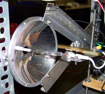
Figure 11. Image of the flashlamp, mirror, and mounting/focusing apparatus.
Initial Jet and Droplet Experiments. Once the pressurized chamber had been completed and pressure tested, a series of jet/droplet experiments were conducted to verify that the jet behaved as predicted and to verify the accuracy of the analysis of jet and droplet behavior. A MathCAD master program, P1ExptCalcs.xmcd, was written to analyze the data.
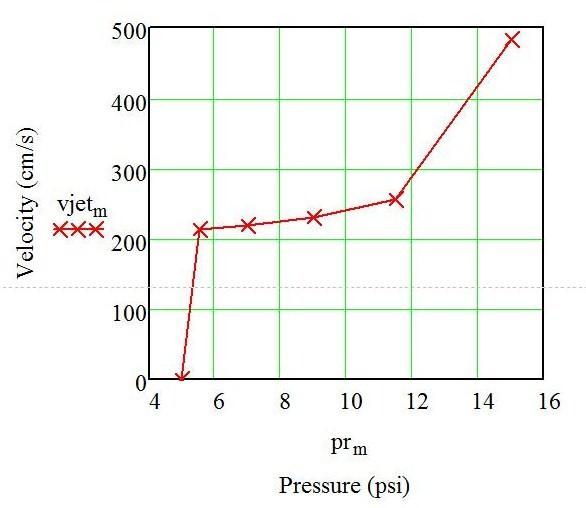
Figure 12. Oil jet velocity dependence on driving pressure.
The first experiment was designed to determine the jet velocity. The chamber was pressurized to varying pressures and the jet liquid was captured in a beaker to measure the liquid volume vs. time. This, combined with an accurate measurement of the jet diameter through microscopic imaging (Figure 14) allowed calculation of jet velocity, shown in Figure 12. This velocity, about 2.5 m/s is consistent with the STI Optronics work [5]. The jet diameter was found to be 0.43 mm, compared with the 0.0015 in (0.38 mm) diameter orifice.
Water jet experiments were also performed, where the jet velocity was found to be approximately 12 m/s. The jet velocity increases with decreasing liquid viscosity. The oil used, standard mechanical vacuum pump oil, is relatively viscous - 55 cst at 40°C.
Droplet parameters were estimated based on a droplet diameter of 1.0 mm. The room temperature properties of the vacuum pump oil (Invoil 19) are not well known, but assuming a 100 cP viscosity and a surface tension of 35 dynes/cm, the Weber number, Wed, is calculated to be 5.7, and the Reynolds number, Red is calculated to be 20.
To learn about the distance at which droplets are formed downstream, measurements were made using the motion of a light cantilever that was impacted by the jet. DHX - analyzes droplet formation distance downstream as a function of driving pressure. The data is hard to take, since identifying the exact transitions are imprecise, a MathCAD program, Jet Integrity.xmcd, analyzed and plotted (Fig. 13) showing droplet formation as a function of the number of orifice diameters downstream. This data is consistent with previous work.
Figure 13. Dependence of jet breakup distance on driving pressure.
Initial Droplet Imaging Experiment Development. The apparatus was first pressure and vacuum tested. The chamber was then filled with oil to a depth of about 5 cm by evacuating the vessel and drawing the oil in. The liquid tested was standard mechanical vacuum pump oil, an oil typical of a low vapor pressure fluid believed to be necessary for the operation of an open-air DHX. The chamber was then pressurized, at which point a rapidly flowing jet emerged.
Figure 14. Image of the jet.
After the liquid jet supply system and the imaging system had been debugged, imaging experiments were performed to investigate the behavior of the jet and the droplets formed from the jet. Droplet jet experiments began with evacuation, pressurization, and oil feed experiments, followed by single stream jet experiments. Simultaneously the flash electrical system was being used and developed to provide instantaneous imaging of droplets of the jet.
The jet resulting from pressurized flow through the orifice as imaged by the microscope using a long exposure in room light is shown in Figure 14. Note that the slight jet curvature is an artifact of the microscope magnification.
Length calibration of the image indicates that the jet diameter is close to 0.5 mm (0.43 mm ave). The image location was such that the jet was not far enough away from the orifice to have broken into droplets. There was no question that the jet did eventually form droplets, because they could be heard impacting the liquid reservoir with a steady frequency.
The imaging apparatus was then moved farther away from the orifice to detect the droplets and to attempt to obtain instantaneous images of the droplets. Figure 15 shows one of the droplet images obtained. This image illustrates the difficulties of flash and microscope setup debugging. The light pulse for this image was measured with a fast photodetector and found to be approximately 100 microseconds long. At a speed of 10 m/s, a droplet will move 1 mm during the exposure, or 0.1 mm for a 1 m/s droplet. It is not clear from the image whether this is a double droplet that has not moved very much during the exposure, or a higher speed droplet that has been motion blurred. The former seems more likely due to the distinct double light spots rather than a streak. This ambiguity is eliminated by decreasing the flash pulselength while maintaining the flash energy, which was in progress at the end of the reporting period.
Simultaneous with the droplet experiments, the flash apparatus was being debugged. The flash electrical system was a crude initial setup left over from a previous project. It had to be repaired and modified to provide an energetic flash, followed by flash pulse duration tests to guide the modification of the electrical the components to be able to obtain a short enough flash. Focusing experiments were performed to position the flashlamp arc at the proper location at the focal point of an elliptical mirror originally used in yet another project. The goal of focusing was to create a light spot size centered on the jet and the focal area of the microscope and somewhat larger than that focal spot.
Figure 15. Blurred droplet image.
The sequence of the significant work performed during flash apparatus development was: 1) First flash - demonstrating that the flash electrical drive system was functioning, 2) First high energy flash - demonstrating that there was adequate flash energy needed for imaging, 3) Flash lamp mount complete - creating the optics needed to focus the flash on the jet, 4) Flash focusing demonstrated - spot and spot brightness on a screen at the jet location showed that appropriate flash energy would be concentrated on the jet, 5) First jet imaging - showed that the location and light intensity were sufficient for obtaining useful droplet images, 6) Flash pulse length measured - allowed comparison with the pulse length needed to form an instantaneous droplet image based on known droplet velocity, 7) First recognizable, blurred droplet images - First demonstration of droplet imaging, 8) Capacitance and voltage modified to obtain a much shorter pulse length - showed that the system could be used to provide instantaneous droplet images, 9) Instantaneous droplet images obtained.
Pressure Oscillation Generation Work. Aside from overall DHX design work, a major task of the entire Phase 1 project has turned out to be an effort to generate the oscillating pressure (amplitude and frequency) needed to create uniform droplets. The experimentally established method (by STI Optronics) was to use piezoelectric drivers. This solution is more applicable to a laboratory environment than to a practical application because 1) Significant power is required (order 1 kW), 2) the apparatus is expensive, 3) the driving electronics is complex, and 4) high voltages are required. Since the goal of this Phase 1 project was to define a practical realization of a DHX, considerable time was devoted to develop an alternate means of generating the pressure oscillations. The history of this effort is given below in a manner designed to explain the investigation, rather than to follow the exact trail of investigation.
Pressure Oscillation Research. Background research was conducted into the STI Optronics literature obtained during the previous Phase 1 project in 1997 [5]. The goal of this research was to determine, in detail, the minimum frequency and minimum amplitude of the pressure oscillation that could be used to generate uniform droplets.
The parameters that characterize liquid jet instability and droplet formation are the jet Reynolds number, Rej = ρluodo/µl, and the jet Weber number, Wej = ρluo2do/σl, where ρl is the liquid density, uo is liquid jet velocity at the orifice throat, do is the orifice effective throat diameter, µl is the liquid viscosity, and σl is the liquid surface tension.
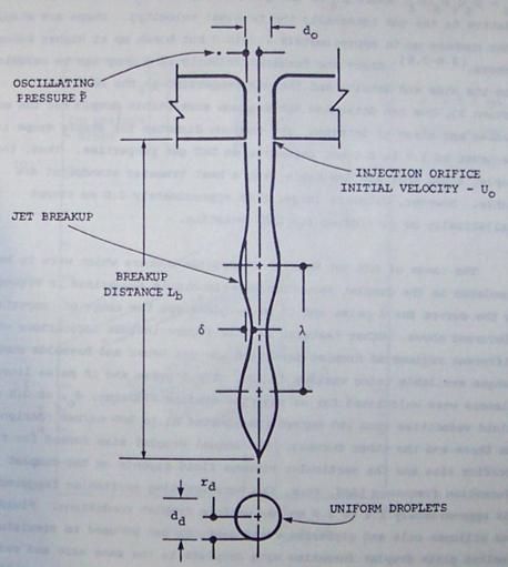
Figure 16. Droplet formation process schematic
Figure 16 illustrates the generic droplet formation process. The columnar liquid jet becomes unstable at a certain number of orifice diameters downstream, at which point it breaks up into (without interference) different sized droplets as a result of a balance between fluid dynamic and surface tension forces (Weber Number).
STI's work was directed at high temperature heat transfer, a regime that is some aspects is very similar and in others very different from that of a high altitude aircraft DHX. Figure 17 illustrates the Re/We regime that they were operating in. They used low vapor pressure liquids, as required for this project, but their requirements on liquids were much more severe, since they were operating at high temperatures, whereas the current program calls for low operating temperature.
For the current experiments, the Weber number, Wed, is calculated to be 5.7, and the Reynolds number, Red is calculated to be 20, which is consistent with the data presented in Figure 17, although placing the experiment in the inviscid regime.
Their results for the oscillating pressure amplitude needed for obtaining uniform droplets is shown in Fig. 18. This indicates that a pressure of approximately 2 kPa is appropriate.
Continuing experiments discussed below showed the wisdom of understanding what this pressure and frequency meant in terms of sound - which is what a broadcast oscillating pressure is detected as by our own senses. Figure 19 gives the relation between sound pressure in Pa with common sound sources, as well as their measurement in (logarithmic) sound units, dB. A 2 kPa pressure amplitude is small in terms of pressures (only 2% of atmospheric pressure), but a very loud sound - about 155 dB. This is consistent with the sound levels designed to be generated by the electrodynamic driver and measured in previous Thoughtventions experiments (over 160 dB measured).
In the present application, the sound itself is not dangerous, since it is only at this level inside the chamber, and is many orders of magnitude decreased as an external sound.
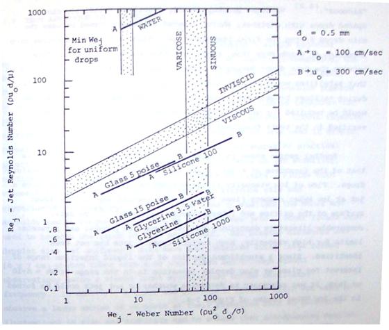
Figure 17. Reynolds Number vs. Weber Number regimes.
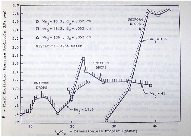
Figure 18. Oscillating pressure amplitude needed for uniform droplet formation.
The final parameter needed is the driving frequency. STI found this to be between 100 and 250 Hz.
Electrodynamic Driver Experiments. The first oscillating pressure experiments used the apparatus shown/described in Figs. 7-10. The electrodynamic driver was used at 60 Hz because of the ease of driving it at this frequency - only a variac was required. It was easy to tell when the driver was operating, due to the vibration in the entire apparatus, in spite of the dampers.
After diaphragm sealing problems were solved, the differential pressure transducer output waveform was inspected on a digital oscilloscope. The frequency of the waveform was measured as 60 Hz and the amplitude varied as expected with variac output. Given the pressure sensor calibration of 1 V/kPa, a pressure oscillation amplitude of 2 kPa was demonstrated.
The next task was to increase the frequency of the oscillation to about 240 Hz. It was originally thought that this was just a matter of driving the motor at a higher frequency, since the motor was advertised to operate at higher frequency. Research into the specific motor discovered that it was typical - designed for resonant operation at 60 Hz. This meant that the motor was attached to springs designed such that the system oscillated at 60 Hz. In other words 240 Hz was far off resonance. As a result QDrive was consulted on how they achieved higher frequency operation. Their response was that it was difficult, but they were able to do it using diaphragms using air springs to change the resonant frequency.
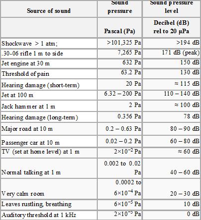
Figure 19. Sound pressure amplitude related to human experience.
As a result, a MathCAD program, Gas Springs.xmcd, was written to calculate what air springs would be appropriate for our application. The purpose of this program was to find the resonant frequency of a piston in a cylinder with gas springs on each side of it. The program finds the oscillation frequency assuming the system is linear, and uses a solver to find the frequency of the nonlinear system. This program verified that for any reasonably sized piston (e.g. 0.5 kg) the gas spring height must be on the order of at most a few millimeters to achieve a 250 Hz oscillation. Discussions with QDrive disclosed that the air springs allowing 300 Hz operation were high pressure, mm stroke air springs that would simply not be able to be used with the diaphragm movement distances that we required to generate oscillating pressures. After significant more work and further discussions with QDrive, it was found necessary to abandon the electrodynamic driver approach, as attractive as it had initially seemed. The motor was just too massive to oscillate and the required frequencies and amplitudes. Mechanical springs are not strong enough to support oscillations at this frequency.
Helmholtz Oscillator Research. The next task was to create a practical experimental technique for creating a 2 kPa amplitude, 240 Hz sound wave/pressure oscillation inside the chamber. At this point in the research it was clear that being able to use an acoustically resonant system would be a great advantage to creating the oscillation. The walls and volume of the chamber would be the resonant condition. Either the volume could be used in some kind of air sloshing mode, or the length could be used as a resonant sound wave.
A 240 Hz sound wave in air at room temperature has a wavelength (330 m/sec)/(240 Hz), or 1.37 m. A resonant chamber with fixed walls would be able to use half wave resonance, or a length of 68 cm, or an open tube could use a quarter wave tube of 34 cm length. Since this is a closed system, other gases could be used to change the resonant length by a factor of the square root of the relative molecular weight. Compared with air, hydrogen would give a factor of 3.8 increase in resonant length, while Xenon would give a factor of 2.1 decrease in resonant wavelength.
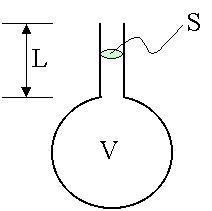
Figure 20. Diagram of a Helmholtz Oscillator.
Dr. Bates' aeronautical and acoustic background indicated that a Helmholtz oscillator was such a resonant system that seemed to be applicable to this problem. A Helmholtz resonator is an acoustic filter element. It is effectively a mass on a spring, a single degree of freedom resonant system. The large volume is the spring and the volume of air in the neck is the mass.
The acoustic length of the neck is longer than its physical length. An additional length must be added at each end to determine the resonant length factors. This added length is related to whether the end of the duct is flanged or unflanged and the radius, a of the duct. In the drawing the end that terminates within the volume is termed flanged (extra length 0.85a) and the end that opens into the atmosphere would be termed unflanged (extra length 0.6a).
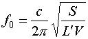
For the case shown the effective length, L' is:
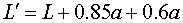
and the resonant frequency, ƒ0 is:
Literature searches on Helmholtz oscillators implied that loud sounds could be generated at musical instrument frequencies - 256 Hz is middle C on the musical scale. A tuning fork for middle C was purchased to be able to easily identify this frequency or those close to it.
Figure 21. Helmholtz oscillator apparatus.
To determine if this concept could be used, the chamber apparatus was modified as shown in Figure 20 to create what was thought to be a Helmholtz oscillator driven by the electrodynamic driver at 60 Hz. According to modeling, the dimensions of the volume and tube were appropriate to create a Helmholtz oscillator with a frequency below 60 Hz that could be tuned through resonance by adding oil to the volume. No resonance was obtained. Further research indicated that side volumes such as those on the chamber would kill the effect. The experiment was repeated using a straight cylinder, again with null results. It was concluded that that phenomenon was more subtle than it seemed. The following rules were given for creating a successful Helmholtz oscillator:
1) General Guidelines
- The neck must be located in the center of the top surface of the main volume for resonance to occur.
- The volume must be sealed for resonance to occur (i.e, no open holes, side ports).
- The volume and neck dimensions must be kept within certain ratios for oscillations of large enough amplitude to occur.
- The air must be able to flow smoothly inside the volume, between the neck and volume, inside the neck and out the neck for resonance to occur.
2. Notes for exciting a resonator by blowing jet of air across the top
- The air jet must be blown uniformly over the top; that is, it should be blown over the top with a square nozzle of similar diameter to the neck opening to observe resonance.
- The strength of the resonance will depend on jet velocity.
- There must be no air leaks around the neck.
The literature, most of it non-scientific, indicated that many Helmholtz oscillators were driven by jets of air blowing across the open mouth of the tube. A series of simple volumes and tubes were assembled. Driving the resonance was attempted using a drum effect and various jets. Successful resonance was obtained only by using a relatively high velocity, thin flat jet across the opening. This confirmed an understanding of the phenomenon, but was not useful for creating a DHX pressure oscillation.
Further research and modeling showed that there were limited ranges of geometries where the oscillation could be maintained, and, further, that the maximum sound amplitude that could be generated with a Helmholtz Oscillator was far below the needed 2 kPa. The reason for this is that the flows necessary for this magnitude of pressure are so large that the losses in the neck cannot be overcome by the driver. For this reason the Helmholtz oscillator approach was abandoned, but it was clear that use of a resonant volume or length would be important for minimizing the apparatus and power needed to generate the required pressure oscillation.
Fast Valve Research. The option of using a fast valve to obtain a 240 Hz pressure oscillation was explored next. In this design one or two fast valves would open and close to supply the oscillating pressure. A frequency of 240 Hz implied an opening time of 2 ms. It is difficult to make valves that operate on this time scale, and even more difficult to make them cheaply. However, a fast pneumatic automation valve was found and purchased. Unfortunately the fast speed necessitated a small solenoid valve, which could not supply enough flow to generate the desired pressure oscillation. This option was then abandoned.
Motor Driven Orifice Work. The focus of the research then shifted to finding a means of mechanically achieving a 240 Hz frequency. The resonant electrodynamic driver was just a mechanically efficient way of generating low frequency sound. The problem is that for mechanical systems 240 Hz is very fast. For instance a rotating system operating at 240 Hz is operating at 14,400 rpm; only race car engines and jet turbines rotate that fast. Some inexpensive, small, motors do operate this fast, so it was decided to try to design a system that could use such a motor to drive an oscillating pressure.
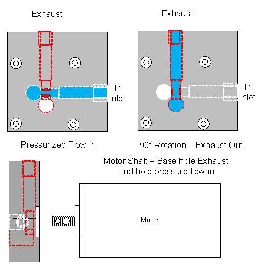
Figure 22. Schematic of the oscillating pressure generation block design. The top figures show the flow (blue) when each holes in the motor shaft is aligned with the appropriate flow passage. Below is shown the motor and block side view, with the flow exiting to a volume to the left.
The concept was to use the motor shaft to gate pressure into and out of the system at the target frequency. By providing an alternating gas feed in and exhaust port out, the average pressure would be maintained, but an oscillating pressure could be established. Furthermore the oscillating feed/exhaust concept could be applied to an average pressure, such as that required for uniform droplet generation.
The concept is shown graphically in Figure 15. Two parallel holes have been put into the motor shaft. The holes are sized to give appropriate flows - the exhaust hole is larger as a result of the lower pressure in the chamber. The flow passages are at different heights in the block and 90° apart, so that flow occurs through each path when the hole in the motor shaft is aligned with the flow passage. The alignment and flow sequence occurs twice per motor revolution, so the motor only must rotate at 7,200 rpm to generate a 240 Hz pressure oscillation.
One of the significant advantages of this design approach is that the flow apertures open and close steadily and in a naturally sinusoidal pattern. This allowed the production of a clean sinusoidal pressure oscillation.
A MathCAD program, Oscillating Pressure Generation.xmcd, was created to estimate the shaft hole diameters appropriate to obtain pressure oscillations on the order of 1 kPa with the motor rotating. The pressure differences between chambers are assumed to be large enough to ensure choked flow. The program showed that the chamber was too large to obtain the needed pressure oscillation, so an internal tube 1.25" ID was added, sealed to the top and bottom plates. An experiment was conducted to test the choked flow analysis in the program, experimental results were analyzed at the end of the program, and demonstrated the accuracy of the program.
Figure 23. Oscillating pressure measurement.
Figure 23 shows the oscillating pressure as measured by the pressure sensor attached to an aperture on the bottom plate of the chamber. The shape of the oscillation was found to be maintained almost up to the maximum motor speed. Pressure oscillation magnitudes of over 2 kPa were achieved.
Figure 24 shows the apparatus used for these experiments. The motor is seen at the top. The motor shaft is connected to the aperture shaft with a flexible alignment coupling so that a precision mount was not required. The pressure oscillation block is shown attached to the top of the top plate of the chamber with the pressurized gas feed on the right and the exhaust port on the front of the block. The block was originally made of all aluminum, but it was found necessary to make a Teflon insert (white) to minimize friction forces on the high speed shaft.
Having demonstrated that it was possible to generate the magnitude and frequency of pressure oscillations needed generate uniform droplets, the apparatus of Fig. 24 had to be converted to be able to generate the oscillations superimposed on the jet driving average pressure. In order to do this, the pressure oscillation block was mounted on the bottom of the chamber top plate, and the internal smaller tube was modified to end above the bottom plate. The pressure feed to the block was plumbed to the side flange. Initial experiments found that leaving the exhaust on the inside of the chamber overpressurized it, so that port, too, was plumbed to the side port as well. The final configuration is shown schematically in Figure 25.

Figure 24. Apparatus used for initial rotating motor-driven oscillating pressure experiments, showing motor mounted on orifice block on oil chamber.
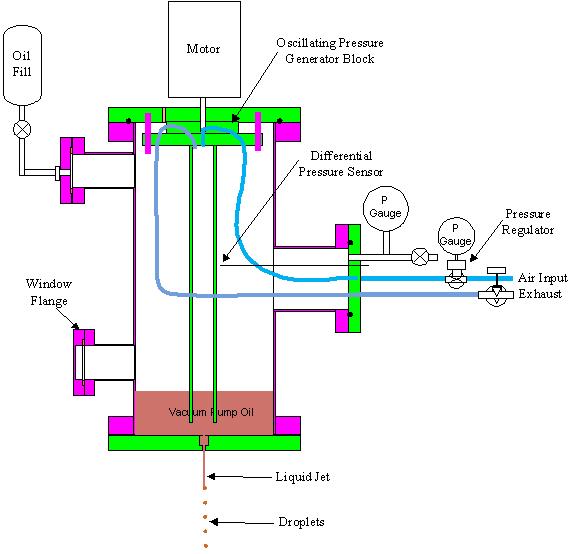
Figure 25. Jet driving apparatus for uniform droplet generation.
The idea was to pressurize the chamber to the pressure appropriate to driving the jet, then turn on the oscillating pressure feed to superimpose the oscillating pressure needed to form uniform droplets. The oscillating pressure would be too fast to blow out the vacuum pump oil surrounding the inner pipe, just transmitting the pressure to the oil reservoir.
The modified oscillating pressure apparatus (before addition of the exhaust line) is shown in Figure 26. Having completed the mechanical apparatus, the gas supply apparatus shown in Fig. 25 was completed, and the differential pressure sensor was mounted on a hole in the inner tube (wires protruding from it are shown in Fig. 26.
Droplet Impact Sensor. The STI Optronics program relied on optical techniques to measure droplet uniformity. Extreme uniformity was demonstrated, but the means used are not that accurate for the determination of droplet mass. Light beam measurements have difficulty determining the start and end of the droplet, and imaging techniques have difficulty measuring the edges of the clear droplets. Beyond this, optical techniques measure droplet diameter, and to a lesser degree, area. Droplet mass is proportional to d3, so that a 10% error in diameter can lead to a 33% error in droplet mass.
For this reason, a better experimental technique was sought for measuring droplet mass uniformity. Since the goal is to measure the mass of relatively high speed droplets, an impact sensor was considered. The force of a droplet impacting a surface was calculated, together with an approximate impact duration. The question was whether an inexpensive pressure sensor was available to measure this impact. Given the area of a typical pressure transducer based on a 3 mm diameter, the inferred pressure was calculated and pressure sensors were researched. It was concluded that a PCB Piezotronics General Purpose ICP Pressure Sensor Model # 111A21 was purchased. This is a capacitive high frequency AC pressure transducer with a maximum resolution of 0.002 psi, or 14 Pa, which was believed to be of adequate sensitivity based on impact calculations. Indeed, this was found to be an excellent technique for measuring droplet time response and mass uniformity as described below.
The mounted pressure transducer being impacted by the jet/droplets from a long exposure, room light image is shown in Figure 27a. The figure shows what is seen by the eye - above the impact sensor (pressure transducer), one can see what is apparently a single stream. Using the standard camera flash, however the individual droplets can be seen in Figures 27b-f. In Figures 27e and f one can see the jet changing into droplets just past the dark stain on the background. It is clear that without excitation, the droplets can be rather equally spaced or very unevenly spaced. It is hard to distinguish size.
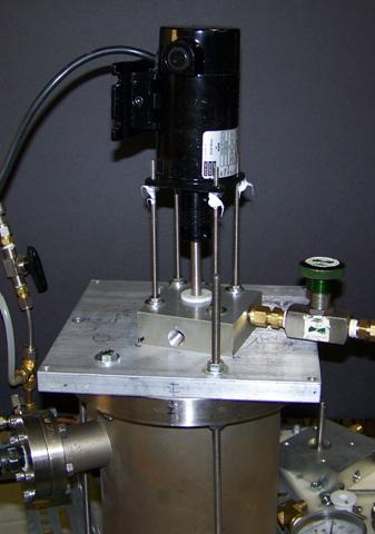
Figure 26. Final oscillating pressure apparatus.
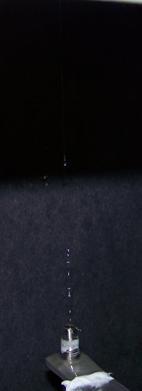
Figure 27a, Figure 27b, Figure 27c, Figure 27d, Figure 27e, Figure 27f
Figure 27. Droplet impact pressure sensor and jet/droplet images. a) No flash, long time exposure, b)-f) flash images.
Uniform Droplet Experiments. The equipment and sensors was tested and experiments begun at low motor speeds. Immediately it became obvious that it would be difficult to equalize the average pressure inside and outside the inner tube. Initial pressure measurements showed a random pressure waveform. This was found to be caused by an overpressurization of the inner volume and bubbling through the oil. It was realized that this process could be used to establish an equal average pressure inside and outside the inner tube simply by allowing the gas to bubble through the oil at constant motor speed until a equilibrium was reached. It was later recognized that the average pressurization due to the oscillating pressure was also motor speed dependent.
The immediate goal was to try to demonstrate that the oscillating gas pressure could drive uniform droplets. A frequency of approximately 250 Hz and a amplitude of approximately 1 kPa was believed to be needed based on STI's research (Fig. 18). After initial tests showed that a jet and an oscillating pressure could be formed simultaneously, although not for long periods, the motor speed was increased and significant pressure oscillations were demonstrated. The motor speed was gradually increased until a period of about 5 ms was measured, and significant, but varying, pressure amplitude was obtained. The pressure and impact sensor signals were fed into a digital oscilloscope, and the traces were recorded at semi-random times during the process. Figure 28 shows a combined trace of impacts and pressure oscillation that clearly demonstrates that droplets have been formed at uniform intervals by the pressure oscillation. This was a key success.
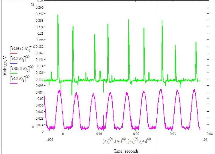
Only the positive half of the pressure oscillation is detected because the pressure sensor cannot detect negative differential pressures. The amplitude of the pressure oscillation is calibrated at 1 V/kPa, so the p-p amplitude (with a 0.5 scaling factor) of the oscillation is estimated to be 0.32 kPa. This probably accounts for uniform spacing, but not uniform droplet mass - which varies by a bit less than a factor of 2 in this trace. This does, however, imply a droplet diameter variation of only about 25%. No satellites are recorded. This behavior is consistent with STI's results; they found that uniform spacing but not uniform size would be established if the oscillating drive pressure was not quite large enough.
At this point, the apparatus was operated at the same jet driving pressure (15psi) without pressure oscillations. A typical resulting impact trace is shown in Figure 29. The time scale is approximately the same. The droplets are spaced and sized fairly randomly, confirming that the impact sensor gives a measure of droplet mass that would be expected.
Next an attempt was made to increase the oscillating pressure. This was found to be possible, but only on a non-equilibrium basis. The exhaust from the pressure oscillation block was closed and then opened, and in the process of equilibration the oscillating pressure reaches significantly higher values than that measured in Fig. 28. Figure 30 shows the impact (above) and oscillating pressure traces (below) resulting from this trial. The scaling factor is 0.2 in stead of 0.5, so the estimated amplitude is 0.8 kPa.
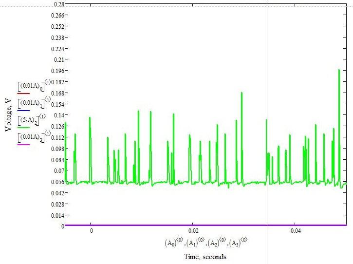
Figure 28. Demonstration that droplet formation interval has been controlled by a driven pressure oscillation.
It was expected that this amplitude would lead to uniform droplets, but the impact sensor still showed a significant variation in amplitude. At this point it was noticed that the higher peaks were narrower, while the lower peaks were broader. It was then realized that the impact sensed was not an impulse but a distributed signal. Two droplets of equal mass but not totally spherical shape would give different heights, but the same area. The data was then examined in greater time resolution to determine if this was the case.
Figure 31 shows four droplets from the data of Figure 30. This data supports the conclusion that the droplets masses are actually much more uniform than is apparent from the peak heights. This tends to imply that the droplet mass uniformity is probably within 10%, and the droplets, if spherical would have excellent uniformity. It was not practical to do a statistical study of droplet uniformity, given the non-steady experiment.
Figure 30. Droplet impacts with higher oscillating pressure drive.
Two points about the data should be noted. The pressure signals of figures 30 and 31 are not sinusoidal probably because the peak magnitudes saturate the detector. This is not clear, but the measured amplitude is a minimum that could actually have been greater. Also, there is a delay between measured pressure peak and the droplet that results from that peak, since the fluid takes time to reach the impact sensor. At 2 m/s, and 30 cm to the sensor, the liquid takes 150 ms to reach the sensor, or 30 pressure oscillation cycles.
Figure 31. Droplet impacts signals examined at greater time resolution.
Further research with this system was not warranted within the constraints of the Phase 1 program. A steady state system similar in design to that described above would have required a different set of orifices and a different chamber. It is unfortunate that increasing the oscillating pressure amplitude using resonance effects could not be investigated, since that would have entailed a variable length chamber. This will undoubtedly reduce the driving power requirements substantially in the prototype DHX system.
The conclusion of these experiments is that the pressure oscillations required to generate uniform droplets can be generated fairly simply and inexpensively combining a motor and fluid mechanics. In the case of a prototype DHX in an aircraft, a different scheme would be employed. In this case a specially modified motor-driven centrifugal compressor would be used. Whereas centrifugal compressor are usually used to eliminate pressure pulses caused by reciprocating pumps, the multiple vane system is well suited to generating pressure pulses if there alternate passages are blocked and the standard vane to case clearance is eliminated. This will be discussed further in the Phase 2 proposal.
4.5. Project Related Industry Interactions
Northrop Grumman Corp. I was contacted by Andrew F. Carl of their Integrated Systems Sector - Air Combat Systems Group. He said they were considering incorporating a DHX in their design. I sent him the final report from the previous Phase 1 project, informed him of the present project, and promised to keep him up to date on project progress. Discovering that Grumman was also a DARPA contractor on the RAPIDEYE program, he said that he would like to hold further discussions about both his and my work, so he initiated a NDA between Grumman and Thoughtventions that was appropriately completed.
Discussions with Andrew have had a major and beneficial impact on the current program. He has sent progress reports and MathCAD programs, and will be sent a copy of the Final Report and Phase 2 Proposal. He pointed out that the DHX would only be one piece of the aircraft system, and that the DHX must be designed with the overall system in mind and the system should be designed with the DHX in mind.
Cooling requirements would originate from the Propulsion, Payload, and Avionics, which would be liquid cooled or in a pressurized box. The Internal Combustion Engine (ICE) had not yet been designed for the aircraft, and thus could be made compatible with the DHX liquid and pumping needs. There are typically two temperatures, the ICE coolant with its associated load, and the payload; there would typically be two cooling loops. Intercooler loads occur at a range of temperatures. As the altitude is increased, propulsion (and cooling) becomes more difficult.
He provided the comparison parameters for a standard plate and fin compact heat exchanger for comparison with a DHX. A 50kW liquid-to-ram-air HX:
Frontal Area: 3.9 sq. ft.
Estimated Dry Wt.: 13.0 lbm (Al core only, not including duct work)
deltaP_water = 8 psid
Drag = 1 x dynamic pressure (50% through core, 25% inlet loss, 25% outlet loss)
In terms of a system approach, the on-board fuel is the largest available thermal sink, and as such is commonly used for thermal management on AV's (i.e. FTMS=Fuel Thermal Management System). A mission profile based thermal analysis, taking into account fuel tank convection to the external ambient, would establish the overall system thermal capacity. The ability to manage energy transfer between ICE coolant, fuel tank and the external ambient via the DHX, and on-board electronics, would be facilitated via a liq-to-liq direct contact HX(s). A stationary cyclone style separator might be adequate, rather than a centrifuge type. It bears further study from a system perspective.
Continued interactions are planned if Phase 2 is awarded.
Aurora Flight Sciences. They were contacted to find out more about their current high altitude heat exchanger designs. They said that they have no one working on heat exchangers. The person doing related work did not return my call requesting information.
5.0 CONCLUSIONS / ESTIMATE OF TECHNICAL FEASIBILITY
The initial high altitude DHX conceptual feasibility study performed by this author in 1997 indicated that this technology was feasible. Engineering calculations and Fluent computer droplet/flow simulations showed that 50kW of heat could easily be exchanged, and that the system would likely be of lower mass and much lower drag. The important conclusions of this work were:
- A practical DHX can be designed to reject 50kW of heat at 80kft (not 65kft as in this project) altitude.
- A DHX system results in very low added aircraft drag.
- A DHX system can be built with significantly less mass and much lower drag than necessary for an equivalent standard tube and fin HX.
- The DHX has the appropriate dynamic range and tolerance of flight conditions.
- A DHX is practical to build and operate without great cost.
- Fluid loss can be engineered to be acceptably low for long duration use.
The present study indicates that the concept is even more promising at this time, thanks to less stringent altitude requirements and advances at Thoughtventions in making the DHX a practical and low mass system.
Current program work has shown the following further indications of feasibility:
- Quantitative and detailed metrics of the design DHX were developed; these indicate that a DHX will be a lower mass system and much lower drag system compared with a tube and fin radiator for any rejection power level.
- A DHX is practical both in terms of engineering, cost, and ease of fabrication.
- There are no development problems foreseen for the system that cannot be worked out in a typical Phase 2 prototype program.
The overall conclusion of the previous two SBIR Phase 1 feasibility studies is that a DHX system for a high altitude, long duration aircraft is feasible, practical, and clearly superior to a standard heat exchanger. A DHX can provide major performance increases for the aircraft.
ACKNOWLEDGEMENTS
Sponsored by Defense Advanced Research Projects Agency (DOD)/US Army Aviation & Missile Command under Contract No. W31P4Q-09-C-0270.
6.0 REFERENCES
1. S.C. Bates, "UAV Droplet Heat Exchanger," SBIR Phase I Final Report, NASA Contract # NAS4-97018, Sept. (1997).
2. Bandrowski, J., and Kaczmarzyk, G. "Gas-To-Particle Heat Transfer in Vertical Pneumatic Conveying of Granular Materials," Chem. Eng. Sci. 33, p. 1303 (1978).
3. Said, Magdi A., Biaxial Test Method for Characterization of Fabric-Film Laminates Used in Scientific Balloons, Journal of Industrial Textiles, Vol. 30, No. 4, 280-288 (2001)
4. A. P. Bruckner and A. Shariatmadar, "Heat Transfer and Flow Studies of the Liquid Droplet Heat Exchanger," in Space Nuclear Power Systems 1985, M. S. El-Genk and M. D. Hoover, Eds., Orbit Book Co., Malabar, FL 119 (1986).
5. W. J. Thayer, K. M. Sekins, and A. P. Bruckner, "Development of High Effectiveness Droplet Heat Exchangers," U.S. Dept of Energy, Report DOE/ER/10918-1 (1985).
6. Dushman, S. "Scientific Foundations of Vacuum Technique," J. Wiley & Sons, NY, NY, p. 693 (1962)
7.0 LIST OF ABBREVIATIONS, SYMBOLS, & ACRONYMS
7.1 Abbreviations
None
7.2 Symbols
| A | surface area | m2 |
| Ag | gas cross-sectional area | m2 |
| Bi | Biot number | |
| cd | droplet drag coefficient | |
| cp | heat capacity | J/kg/K |
| d | diameter | m |
| f | droplet generator frequency | s-1 |
| Fdrag | drag force on droplet | N |
| H | device height | m |
| h | heat transfer coefficient | W/m2/K |
| kl | thermal conductivity | W/m/K |
| L | length | |
| l | gas-droplet interaction length | m |
| ld | droplet spacing | m |
| m | mass | |
| md | single droplet mass | kg |
| mg | total gas mass flow | kg/s |
| mo | liquid mass flow though single orifice | kg/s |
| Mg | gas molecular weight | kg/gMol |
| nd | total number of drops per second | s-1 |
| N | Number of | |
| Nu | Nusselt Number | |
| P | power transferred | J |
| p | pressure | Pa |
| Pr | Prandtl number | |
| R | universal gas constant | 8.314 J/gMol/K |
| Re | Reynolds Number | |
| t | time | s |
| T | droplet temperature | K |
| ΔT | total temperature change | K |
| u | velocity | m/s |
| V | volume | m3 |
| W | device width | m |
| We | Weber Number | |
| x | local droplet position | m |
| β | local gas-droplet volume ratio | |
| µ | viscosity | kg/m/s |
| ρ | density | kg/m3 |
| a | air |
| d | droplet |
| g | gas |
| j | jet |
| l | liquid |
| mm | millimeters |
| o | orifice |
| r | relative |
| R | rate |
| so | silicone oil |
7.3 Acridnyms
DHX - Droplet Heat Exchanger