Fiber Optic Slipring
40 Nutmeg Lane
Glastonbury, CT 06033
ABSTRACT
As engine designs become steadily more complex and the demands of propulsion technologies become steadily more severe there is a need for developing advanced instrumentation technologies. Slipring systems are presently utilized extensively in test programs where data from rotating sensors is obtained. Current contact slipring systems have inadequate capacity, size and durability. A fiber optic slipring can avoid these problems. By focussing light from a laser diode on a peripheral ring of fibers, data can be transmitted across the gap between a rotating element and a fixed case. The system time response is extremely fast, allowing very high data rates per ring, and large numbers of channels can be accommodated. The system uses inexpensive components, is not subject to contact degradation, and has the insensitivity to electrical noise characteristic of fiber optics.
COMMERCIAL APPLICATIONS
The proposed system has the potential for providing real time sensing of commercial jet engine operation. This would improve the control and efficiency of such engines.
The Problem. An often neglected aspect of propulsion research is the development of instrumentation used to acquire engine test data. Most of the recent advancements in engine design have been made possible by the ability of the instrumentation to make new and more precise measurements of engine parameters. As engine designs become steadily more complex and the demands of propulsion technologies become steadily more severe there is a need for developing advanced instrumentation technologies. A variety of specific problems in this area have been identified by NASA's Propulsion Instrumentation Working Group (PIWG), which was formed to cooperatively address present and future needs for instrumentation and sensor research and development.
Slipring systems are presently utilized extensively in test programs where data from rotating sensors is obtained. Current contact slipring systems have inadequate capacity, size and durability. These slipring systems are subject to wear at the brush/ring contacts that require significant maintenance, particularly in high rotor speed applications. There is need to replace present day contact ring slipring systems with non-contact systems for both environmental and maintenance concerns.
The Innovation: The innovation of this work is the design and fabrication of a fiber optic slipring. By focussing light from a laser diode on a peripheral ring of fibers, data can be transmitted across the gap between a rotating element to a fixed case. The time response of the diode source and photon-level-sensitive detector is extremely fast, allowing very high data rates per ring. Large numbers of channels can be accommodated by either multiplexing, by segmenting the circumference, or by providing additional complete detector disks. The system uses inexpensive components, is not subject to contact degradation, and has the insensitivity to electrical noise characteristic of fiber optics. Furthermore, the system can take advantage of the tremendous advances in fiber optic communications that have taken place during this decade.
PHASE I TECHNICAL OBJECTIVES
Background Fiber Optics - At this time fiber optics is a massive industry as a result of the replacement of copper telephone lines with silica fiber optic light guides. The advantages of fiber optics in terms of signals/cable and high transmission rate at competitive cost are so large that optical communication is rapidly replacing conventional systems. There is thus a large literature and commercial base in silica fibers. More recently fiber optic sensing has become an important field [e.g. 1, 2] because light-based sensors are immune from the electrical interferences that is usually the bane of conventional high-sensitivity sensors.
This background discussion can only touch on the important factors of fiber optics and fiber optic imaging. The topic begins with the production, materials, properties, and transmission of single fiber. Optical fibers contain light within a thin, very long cylinder, functioning as an optical wave guide. The light is collected by focussing or by transfer from an object, and contained within the fiber by internal reflection. Snell's law in optics determines the path of the light into and through the fiber. From media 1 to media 2 the product of index of refraction, n, and the sine of the ray angle from the surface normal is conserved:
n1sinθ 1 = n2sinθ 2
Extremely low transmission loss is critical for propagating signals over long distance. The most basic property for losses is the internal reflection. To achieve total internal reflection at the fiber walls the fiber core is surrounded with a material that assures total reflection. Total reflection is done a number of ways; step-index optical wave guide uses a higher n material cladding, gradient-index fibers are made with a steadily increasing n with diameter, and metallic coatings use standard reflection. Once theoretical internal reflection is achieved, the details of the fiber properties such as impurities, scatter by imperfections, and other effects become important.
Another important fiber parameter is the Numerical Aperture, or NA. This parameter defines the efficiency of collection of light at the entrance to the fiber.
NA = sinθ 1 = (n22 - n32)1/2/n1
where the external material index is n1, the fiber core index is n2, and the cladding index is n3. Light rays with too large an entrance angle are reflected from the surface and not captured within the fiber. NA also determines the effectiveness of focussing light on the end of a fiber with lenses. Glass, typically has NA = 1.0, whereas for plastic NA = 0.6.
Fibers are made by pulling a cylinder through a die to successively smaller diameters. While there has been long involvement of silica fibers in image bundles and laser power delivery, the use of non-silica fibers is more recent. The scientific, medical, and engineering aspects of fibers made from crystalline, UV and IR glass, plastic, and hollow materials has become important. This includes IR fibers transmitting from 2 to 20 µ m, fibers that are useful in transmitting UV wavelengths shorter than 350 nm, and plastic fibers. Fabrication, characterization and applications of these specialty fibers are areas of expanding work.
The formation of images by fiber optic bundles is done by maintaining the relative orientation of the fibers and collected spots of light within the bundle so that each fiber is at the same relative location in a plane at the entrance and exit. Scrambling and breakage within the bundle results in local defect, whereas overall distortion can occur because of macroscopic changes in the bundle. The ratio of core area to total area ranges from about 70-90%, and the light passing between the fibers must be blocked.
Fiber optic bundles distort light in other ways also [3]. Light that enters a single fiber at one angle will not emerge at the same angle (azimuthal scrambling). A solid angle of light collected at the entrance to a fiber will also change at the exit if the numerical aperture changes (beam spreading). There are also wavelength dependent effects that occur in scientific imaging.

Figure 1. Schematic of fiber optic slipring concept.
An important aspect of imaging fiber optics is also how to couple an object to an array detector (CCD) through the fiber optic bundle. The most efficient method is direct coupling, but lenses are usually used for image transfer because the fibers cannot usually be put against an object without damaging both. An exception is when the fiber bundle is potted directly onto a CCD chip. This is efficient but leads to effects of the mismatch between the fibers and the CCD pixels. The overall system light collection efficiency is an important parameter.
Fiber Optic Slipring Design Experiment Design
The basic concept of the fiber optic slipring system is illustrated in Fig. 1. Signals from the rotating sensors drive the light output of a laser diode, which is focussed by a microlens onto fibers attached to a stator fixture. The fibers are distributed around the periphery of the stator as illustrated in Figs. 1 and 2, where the fibers form a continuous layer without gaps.
Specifications for the slipring are reproduced in Fig. 3. These specifications translate into a variety of physical and operating constraints on the
fiber optic slipring system, although the use of a fiber optic system may modify the specifications themselves. The primary constraints are the g loading on the rotating components, the operating temperature and humidity, the possibility of contamination, and the capacity of data transmission.
These specifications must first be understood in terms of a standard slipring, where electrical contact is made with the rotating sensors by using a fixed brush (graphite in motors) that slides along a rotating surface. The sliding contact must be maintained at all times, so there is a contact ring surface on the rotating disk that must be devoted to this contact. The physics of the sliding surface interaction is very complex. The sliding surfaces must be forced together (spring loaded) to a limited degree to maintain contact but minimize heating and erosion. Friction heating and wear are inherent characteristics. Multiple channels imply multiple contacts or multiplexing. Friction heating translates into the need to operate at elevated temperature and with air cooling if necessary. Environmental factors such as contamination (dust or oil between the contacts) and humidity can change the electrical properties of the contact.

Figure 2. Schematic of fiber optic slipring system; selected fibers out of a continuous layer are shown.
For this reason contact sliprings are often built as sealed or pressurized systems with all of the associated problems of high speed sealing. The radius of the contact and the rpm determine the linear sliding speed, which determines the severity of the application.
The fiber optic slipring avoids many of the problems associated with an electrical contact slipring. The most important of these is that there is now no sliding contact and thus there are no problems maintaining this contact. The only heat generated by the system is related to the operation of the laser diode, and this should be insignificant. Many laser diodes will not operate above 50°C, which is well below the 200°C given in the specification. Since no heat is generated, however, this constraint can be relaxed unless the entire environment is operating at this temperature. The primary issue analogous to maintaining contact for the fiber optic slipring is to maintain alignment
| Mechanical Requirements | Maximum Speed | 20, 000 - 60,000 RPM |
| Temperature Range | 0 - 400 ° F without cooling (including input connector), a less preferable option is 0 - 150 ° F with forced air cooling. | |
| Humidity | System should be sealed to avoid humidity or other contamination problems | |
| Standard Sensor Capacity | Strain gages, Thermocouples |
minimum of 24 to 96 channels simultaneously: |
| 2 channel switching is a less preferable option for the larger capacities. | ||
| 14 - 48 channels with temperature channels mix and match with strain gages desirable | ||
| Sensor Specifications: Strain gages |
Standard Gage Type | 120 - 350 Ω GF= 1.7 to 3.2 |
| Excitation | constant current mandatory, capable of driving 750 Ω , current level requirement varies with user, desirable to be selectable by user | |
| Range | 0 - 4000 µ ε p-p with approximately 50% overrange capacity, desirable to be adjustable to meet changing test conditions | |
| Bandwidth (3dB) | 20 Hz - 40kHz | |
| Typical Resolution | 5 µ ε RMS | |
| Sensor Specifications: Temperature |
Type | K (Chromel Alumel) |
| Range | 0 - 2000 ° F | |
| Resolution | 1 ° F | |
| Absolute Accuracy | 5 ° F | |
| Output Specifications | Strain | If analog, a ± 3-5 volts level full scale, adjustable at receiver. Users would adjust levels to be compatable with their data systems. If digital: "standardized" format (TBD) scaled in µ ε . |
| Thermocouple | If analog: mv output equivalent to type K output referenced to a standard reference temperature. Option of output linearized to ° F. If digital: "standardized" (TBD) format scaled in ° F. |
Comments: Overall diameter of the mounted assembly fit within available engine or rig "cavity" e.g. AlliedSignal requires diameter < 4.5", including provisions for air cooling.
Figure 3. Slipring Performance Specifications
of the laser focussing on the fibers. This can be achieved relatively easily by mounting the fibers on a flat surface (easily machined by turning) and by potting the laser and microlens on the wheel. Vibration is necessarily insignificant for the system to be able to function at the specified high speeds, so movement of the focus spot off of the fibers will not occur after initial alignment of the stator with the axis of rotation. Contamination problems are only important in terms of distorting the beam path or obscuring the fiber surfaces. Both of these can be avoided by recessing the micro lens slightly and by adding a low velocity airstream across the face of the fiber optics.
For a fiber optic slipring the electrical specifications translate into the conversion of electrical signals into optical signals. The fiber optic slipring could be made into an analog system by using square, unclad fibers, but a digital system would be more reliable for round fibers. The analog signals from the rotating sensors would be converted into digital signals at the sensors themselves or in some central rotating digital signal processor (DSP). Such DSP's are currently available in microsized packages. The problem of supplying large numbers of data channels is addressed in the design description below.
Fiber Optic Slip Ring Data Transmission. The basic goal of the fiber optic slipring is to transmit data accurately across the gap between the rotating components to the fixed laboratory frame. The conceptual solution proposed here is to focus the modulated light from a moving laser diode onto a sequence of fixed fibers. All of the fibers are joined into a bundle that is connected to a single detector.
The bundle can be commercially ordered, potted at one end and free at the other. Another advantage of the entire system is that it doesn't matter what arrangement the fibers are in; a fiber end at any location around the periphery can have it's other end occur at any location at the detector and still have the same ability to transmit its signal to the photo detector tube. The next fiber in sequence around the rim of the wheel can come out at some other random location next to the photo detector input face. This will not be true for the segmented data channel concept, where fibers from each separate span on the outside of the wheel will be attached to its own photo detector.
The fiber optic slipring concept uses very similar laser diode and optics to optical disk recording systems. These systems may be directly usable and will be investigated in detail, but their components are not adapted to transmission across a relatively large gap.
It can be shown that placing fibers spread from a fiber bundle around the periphery of a disk is practical. For a slip ring disk diameter, dd, and a fiber diameter, df, if the fibers are in contact around the periphery of the disk the total number of fibers, nf, needed to have fibers completely around the disk is:
nf = π dd/df
For a 0.5 m diameter disk, and 150 µ m diameter fibers, about 10,500 fibers will be needed for a single layer of fibers. Assuming that a large number of identically sized circular the fibers are then close packed into a circular bundle, the area of the bundle is approximately 110% the size of the total area of the fibers. The area of a single 150 µ m diameter fiber, Af, is
Af = π df2/4 = 1.76 x 10⁻⁸ m2
And the total circular fiber bundle diameter, db, is then
db = (4Ab/π )0.5 = [(1.27)(1.1)(1.05 x 10⁴)(1.76 x 10⁻⁸)]0.5 = 1.6 x 10⁻² m
db = 1.6 cm
This is a reasonably sized bundle. A double layer of fibers only increases the bundle diameter by a factor of 1.4. A standard illumination fiber bundle such as that already at Thoughtventions is 1.4 cm in diameter and is filled with 50 µ m diameter fibers. The area of this bundle is 1.5 cm2, and assuming a 0.5 m disk, implies a fiber layer approximately 0.1 mm thick, or about 3 fiber layers.
The gap between the focussing lens and the receiving fibers is an important parameter for the overall system. If too narrow a gap is required the entire system will become impractical. Initial assessments indicate that a 1 mm gap is achievable, and this would make the system much more attractive. There is a minimum practical gap for setting up assemblies. The entire rotating assembly may move with respect to a fixed platform as it warms up with operation. Typical thermal expansion coefficients are 10-5/°C, so a 100°C operating temperature would lead to an expansion of 1 mm over a 1 m mounting fixture for the engine. Total movement of fixtures within bolt holes will be on this order, as well. The 1 mm gap is probably a good goal, as well as a means to adjust the fixed ring during operation. Even if the system is aligned so that the focussed spot stays on the fibers, an axial offset will cause a change in spot size with rotation angle. This problem should not be too severe, however, since the focus spot is large compared with the source size, the focussed beam will be narrowing only slightly and the change in spot size with distance will be small.
Experiment Design. The fiber optic slipring system will be demonstrated experimentally when funded. This can be done by building a small high-speed rotating disk experiment as shown in Fig. 5. A high speed motor drives a bearing-mounted shaft that supports a rotating disk that has the diode laser and microlens attached to its edge. The spinning disk will have to be balanced, but the added mass of the diode and lens will be small. A stator disk will be mounted as shown and fibers attached to its face as shown. For this geometry all of the fibers are the same length which is appropriate for a commercial fiber bundle. The fibers will be supplied from a bundle that is potted on one end and free on the other. The fibers will be on the order of 100 µ m in diameter, but may be as large as 150 or as small as 50 µ m.
Laser/Lens Assembly. The laser/lens assembly must be adjustable to control the spacing between the lens and the fiber ends, as well as the spacing between the laser output and the lens. The details of this fixture will depend on the fabrication geometry of the specific laser diode and lens. Laser diodes are commercially offered with integral optics for collimating (beam generation) or focussing (laser disk writing). Far focusing (focal length large compared with diode aperture) systems are needed for this application, and this is not a standard commercial system, so appropriate modifications will depend on the laser diode packaging offered. Microlenses are offered separately, one of these would have to be mounted such that the lens axis coincides with the laser axis, and this is difficult to do on such small scales. The fixtures will have to be strong enough to withstand the centrifugal forces generated by the high rotation speed of the disk. A series of identically mounted diode/lens systems will be made to test different types of diodes and lens.
A standard contact electrical slipring will be used to transmit power to the laser diode system as well as data signals. Since the diameter is not great the demands on the slipring are not great, and any one of a number of standard models will be sufficient.

Figure 4. Schematic of the apparatus used to demonstrate feasibility of the fiber optic slipring system.
Multichannel Design. Multiple data channels can be obtained in three basic configurations. Since the time response of the system is expected to be extremely fast, multiple data signals can be compressed into a single physical channel using standard multiplexing techniques. DSP's that perform the digitization of the analog signal can also perform the multiplexing. The number of channels that can be managed is roughly proportional to the ratio of signal bandwidth to the carrier bandwidth. A 1 Gb/s data channel can carry hundreds of 40 khz data signals. Data sampling could be used. For a 0.5 m diameter single disk operating at 20,000 rpm, with 10,000 150 µ m diameter fibers the transit time across a single fiber would be 0.3 µ s, and as long as the sampling time avoided this resonant period and consequent fiber light overlap effects most data transmission problems will be avoided. Frequency encoding can also be used.
Another way to add channel capacity is to add multiple, separate axial layers of fibers and diode lasers. This could be done in a sandwich arrangement or at totally separate axial locations. The design that uses fibers distributed around a circle also presents the possibility of multiplexing signals by using distinct angular segments for each channel. If the fibers for every 30° of angle are bundled to a separate detector, nine separate channels could be created.
Component Fabrication
This effort will fabricate and procure the previously defined components as well as the rotating test apparatus. The detailed specification of the components will be discussed below together with important fabrication questions.
Laser Diodes. There are many types of laser diodes commercially available with a wide variety of wavelengths, source sizes, beam quality and divergence, beam power, operating voltage and current, noise level, and a number of other important factors. Phase 1 research will determine which type of laser diode is appropriate for this application.
For the application of transferring a high frequency digital signal over a significant gap, beam quality, source size, and time response are the most important factors. High power is not necessary, and stability requirements are probably mild compared with current diode specifations. Beam quality will be an important issue, since non-gaussian beams are characteristic of laser diodes. The laser source size and beam quality together with lens properties determine the focus spot size.
A best-case scenario for laser diode characteristics may be presented by the Circulaser diodes produced by Blue Sky Research. These laser diodes are Index Guided, ALGaInP material, single mode laser diodes with an integrated internal beam correcting optic. They are hermetically sealed, and operate at wavelengths near 650 nm where detectors are most sensitive. Laser power offered varies from 5 to 30 mW. Beam divergence is 6 degrees, the source aspect ratio is 1.2 to 1.0, and the numerical aperture (NA) is approximately 0.11. The diode comes in a standard 9 mm diameter circular package. Maximum rated operating temperature is 50°C. This is a shorter wavelength with better beam divergence than most laser diodes available.
As with most diode laser specifications, crucial properties are usually excluded from the specifications. For this laser the effective source size is a few µ m, and the best case the focal spot size is 3-4 µ m. The 6° beam divergence specified with the laser does not represent the light divergence from the few micron source, but the divergence of a much larger beam already manipulated by optics. A larger beam will have less divergence. Most laser diodes can only be focussed in much larger spots, than this laser, however. For the present application, the desired spot size is around 50 ° m, or about 10 times the best focus size. This implies that the 50 µ m spot size can be obtained using focal lengths long compared with the spot size. For a gap of 1 mm a 50 µ m diameter beam would have an aspect ratio of 20, which should be very possible using this type of laser. Many other types of lasers are available and will be investigated for analogous behavior.
Rapid time response is characteristic of diode lasers, since they are solid state, microelectronic devices. Effort will be made to investigate these lasers for maximum time response to maximize system bandwidth. Time response is not even given for the Circulaser; fast laser diodes will probably have poorer beam quality, but the few micron source size is typical for the lower power lasers. The 10:1 source:spot size ratio should allow adequate focusing, but perhaps not over relatively long distances. This must be investigated. The hermetic packaging limits environmental sensitivity; the major factor will be the sensitivity of the diode to its operating temperature. An important factor may be the maximum operating temperature.
Focussing Optics There are a wide variety of microlens designs commercially available, even aspherics. Single wavelength light transmission simplifies lens design, and many laser diode packages are sold with . The CircuLaser cited above boast diffraction limited performance, which makes it exceptional. Simple lenses can be used in this case. Often a specific lens/laser focussing assembly is made to focus a spot at a distance, but in actuality forms a narrow beam waist that can only be predicted using complex wavefront analysis. This functions as a usable spot for fiber optic detection purposes, however. A variety of lens types will be investigated and tested.
Fibers. Standard silica fibers seem to be the best choice for this application. Transmission losses over the relevant length are minor, transmission bandwidth is wider than the wavelength choice of laser diode types, and the fiber is relatively cheap. Any number of manufacturers could supply the fiber, but it will be much better to buy a non-imaging fiber optic conduit. In this case the fiber bundle can be purchased potted on one end and loose on the other.
The free fibers can be spread around the periphery of the stator and cemented in place. Good fiber packing can also be achieved with care by mounting the disk horizontally adding a thin coating of optical cement to the surface, and then adding a layer of fibers by hand, arranging them without gaps by using an eye loop. The alignment of the ends can be done approximately. When the assembly is complete the disk with its fibers attached can be mounted and the rotating disk used to polish the ends of the fibers to a perfect radius.
In another program, the PI, Dr. Bates, performed a similar task. This program, "Controlled Crystal Growth Using Auxiliary Optical Heating and Optical Diagnostics [4]," used a high power light source (lamp) to heat a crystal ampoule in an operating furnace using fiber optics. Light energy was fed into a fiber optic bundle at one end outside the crystal growth furnace, while the fibers from the other end of the bundle were spread around the ampoule inside the furnace. Enough power transfer was demonstrated to control the crystal growth [4]. This program also dealt with all of the issues associated with maximizing the light into fibers, and the light transmission losses associated with individual fibers and bundled fibers. This concept is exactly the reverse of the concept proposed here. This apparatus is available and may be used for this project. The quartz fiber bundle is 14 mm in diameter and approximately 60 cm long.
The surface of the wheel will be coated with potting glue and then the fibers will be spread around the periphery in two separate layers, as shown schematically in Fig. 4 . The fibers can be glued in place and polished to be at a uniform radius/gap by attaching a fixture to the rotating wheel. Some fibers may be broken in the process of attachment, but these can be eliminated during the process by applying a light source to the end of the fiber bundle. The fiber ends appear clearly as dots of light if they are unbroken; only unbroken fibers will be glued to the wheel.
Photodetectors. Table 1 shows a comparison of different types of light sensors. Communications fiber optic systems operate at wavelengths in the near infrared because laser diodes were first developed at this wavelength and are the most well developed. This restriction is no longer the case for laser diodes, and although it may be appropriate to take advantage of communications fiber optic systems, other wavelengths may be more desirable to optimize focussing or photodetection. Cost is probably not an issue in this application. Sensitivity is probably not an issue either, since many detector types are now sensitive at the photon level.
One characteristic that is important is the sensitive area of the photodetector and the uniformity of the sensitivity across the area. For this application the light will be coming from different points in the comparatively large fiber bundle depending on which fiber the laser is illuminating as it passes around the circle. In this case the sensor must have a large area. Photomultiplier tubes seem almost ideal for this case. For contact sensing (and minimum light loss) each small area that is illuminated by a single fiber should have a very similar sensitivity to each other area. If this is a serious problem it may be possible to pull the fiber bundle back from the detector face and add a reflective tube around the gap, spreading the light from each fiber over a much larger area. For this to work properly the sides must have very high reflectivity and there must be no significant gaps in the enclosure.
It is also possible to add a cone non-imaging light concentrator to the system. In this concept a cone with a reflective surface is fabricated with a base the same diameter as the fiber bundle and a truncate apex the size of the detector. Light that enters the base at an angle not too far from the axis of the cone is reflected off the sides down the cone to the apex hole. This allows a much smaller detector to be used compared with the diameter of the fiber bundle. The amount of light lost will be determined by the exit angle of the light from the fibers (usually about 60°).
Time response (dynamic range) of the detector is also important. Fast time response will allow more multiplexing, and thus more channels. Linearity is less important, since this will be a digital system. Physical size should not be important, given that the sensitive area must already be large.
Component Testing: This effort allows optimization of the laser diode, the microlens focussing system, and the fiber detection system.
Laser Diode. This subtask will test the candidate lasers for power, beam properties, time response, environmental sensitivity, and stability. As discussed in Task 2 beam properties will be critical for proper focussing. Rapid time response will be critical for maximizing the frequency bandwidth of the system. The most important aspect of environmental sensitivity will be the sensitivity of the diode to its operating temperature. Power, beam properties, and time response may be temperature dependent, so that temperature variations may lead to signal variations. Temperature variations will necessarily be relatively slow, so a digital system will be naturally immune to this type of variation if the variations are within threshold tolerances. This is another reason to avoid analog data transmission, however, and one factor affecting diode stability. Wavelength stability should be unimportant because the detector is broadband with only very slowly varying sensitivity relative to the laser wavelength shift. The properties of the diode may also change during its lifetime and as a function of output power, but the state of the art in laser diode technology has advanced to the point that these effects should be unimportant; most laser diode applications are more demanding than this one. An important factor will be the maximum operating temperature, and this temperature will have to be investigated through tests.
Microlens Focussing System Laser focussing must be tested to determine the size and the quality of the spot focussed on the fiber ring. The quality of the spot will be determined by its two dimensional intensity distribution. The goal is to create a relatively high intensity spot with a diameter that is one or two times the fiber diameter. The spot quality can be tested in a simple manner by using a single fiber mounted on a translation stage as a detector. The spot intensity distribution can be deduced by moving the fiber with respect to the spot. Much smaller optical pinholes are also available for inspection of the spot.
Fiber Detection System. The fiber detection system must be tested for uniformity around the periphery, absolute sensitivity, noise level, and sensitivity to stray light. The system must be tested before the fibers are attached to the stator disk to identify what effects are caused by the fibers and detector, and what effects result from the light transfer to the fibers attached to the disk. Absolute sensitivity and noise level will be tested in isolated operation, as well as in the assembled system. Sensitivity to stray light is an important characteristic for the final system. The fiber bundling and fiber cladding should prevent any light noise entering the system except at the end of the fibers. The limited NA of the fiber will also limit stray light collection. The angle of the stray light that can enter the fibers will be measured.
The uniformity of light detection by the photodetector through fibers must be tested carefully. The most accurate way to test this will be to mount a pinhole on the rotating disk, align it with a fiber ring, rotate the disk slowly, and measure the light output using an incoherent source mounted on the disk to illuminate the pinhole. The resulting detector output will ideally be a totally constant signal with slight amplitude variations.
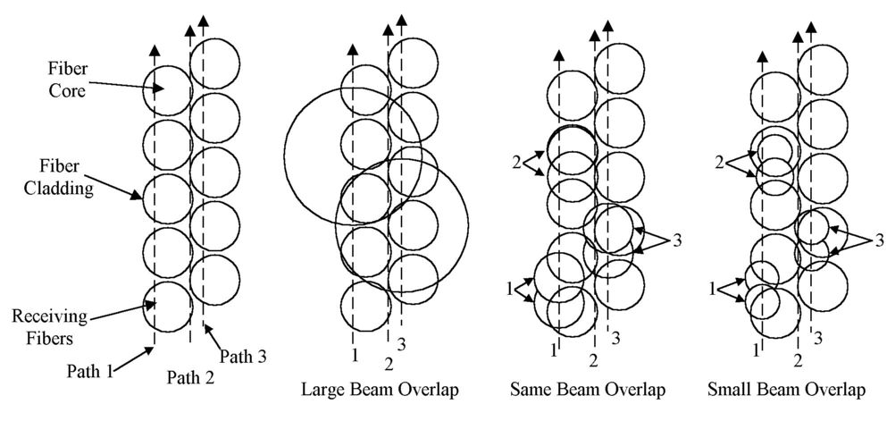
Figure 5. Schematic of the effect of beam size on fiber light detection.
The fundamental cause of amplitude variation in the fiber optic slipring system proposed here is shown schematically in Figure 5. There are three distinct spot sizes cases and three distinct spot paths over the fiber layers that describe the size and location matching of the laser focal spot with the fiber layer. The path possibilities are shown at the left of the figure. The laser spot can pass down the centerline of two layers, as in Path 2, it can be close to this centerline, as in Path 3, or it can be more than a fiber radius away from the centerline, as in Path 1. If the spot is significantly larger than the fibers, the large beam overlap case results. In this case as the detected light does not vary much as the beam travels down any path, but a significant amount of laser light is lost from the system. For the case where the laser spot is approximately the same size as the fiber (Same beam overlap), little light is lost unless the beam is not centered on the layers as in Path 1. The amplitude of the detected light varies significantly along the path (cases 2 and 3 in the Same Beam Overlap figure) depending on whether the spot is directly over a fiber or between the fibers. The light amplitude variation is larger if the fiber is not centered on the fiber layers, as shown for the two spots in case 1. This amplitude variation is significantly larger for the Small Beam Overlap case, since the beam size is now closer to the size of the space between the fibers. The conclusion is that if amplitude variation is more important than light losses, the spot should be about twice the fiber size. If light losses are more important than the amplitude variation the spot size should be approximately the size of the fibers. In all cases it is important for the spot path not to be misaligned with the centerline between the fiber layers by more than a fiber radius in the case of the smaller spot and a fiber diameter in the case of the larger spot.
Since the fiber diameter is about 100 µ m, the laser alignment will have to be very accurate. By providing for a tilt adjustment mechanism this alignment can be relatively easily obtained by simply adjusting the tilt to give the maximum signal with the laser and fiber detector operating as the disk is spun slowly.
Rotating System Testing. Once the fiber ring, laser diode, and focussing lens are set up the response of the system to a constant laser output will be tested with the rotating disk at a variety of fixed positions. Worst, typical, and best case disk angular positions will be determined for testing and results documented. Next focussing will be varied, together with lens/fiber gap, again monitoring the detector response at fixed laser power and disk location. These tests will be repeated at slow rotation speeds. Once these tests are used to optimize the experimental configuration, the system will be tested again at slow rotation speeds using a variety of square pulse and fixed frequency laser drive inputs, measuring detector response and comparing it to the input signal using an oscilloscope and computer data acquisition. The system will be undergo preliminary balancing at low speeds.
Prototype Design
The first part of this effort will be to perform and evaluate tests of the fiber optic slipring system at high rotation speed. The goal is not to operate at the very high speeds specified in Fig. 3, but to operate at speeds high enough to demonstrate that any problems associated with fiber slipring systems can be resolved. Areas of investigation include the effects of high-g loading, vibration, gap effects and dynamic interaction effects.
High-g Loading. The effects of high-g loading will primarily be concerned with the mounting of the fixtures for the laser diode and the microlens. The small size and mass of these components will minimize problems in this area, but care will have to be taken that the focussing does not change significantly during operation.
Vibration This again is a question of the movement of the focus spot from its optimum path over the fibers. In this respect, the high rotational speed of the system is an advantage. In order to be able to operate at rotating speeds in the tens of thousands of rpm, the rotating components must be extremely well balanced. Vibrations are practically non-existent except when resonant frequencies are crossed during spin-up, and these frequencies are by design far from nominal operating conditions.
Gap Effects One of the goals of research is to optimize the gap in the system. The effects of high speed operation on the gap optimization must also be considered. These should primarily be associated with the necessarily high speed air flows in the gap. As long as there are no large density gradients that would distort the beam focus, gap effects at high speed should be unimportant, but there may be some unusual effects present, or some effects associated with practical high speed jet engine rig design that must be taken into account.
Dynamic Interaction Effects One important aspect of high speed operation is a resonant frequency that is defined by the width of the fibers and the peripheral speed of the disk:
ω df = vp/df
For a 0.5 m diameter disk operating at 10,000 rpm, the peripheral speed is 260 m/s. For a 100 µ m fiber the critical frequency will be a few Mhz. For signals at a higher data rate there will be fluctuating light in each fiber, whereas for lower frequencies the light transmitted by each fiber will be constant, varying slowly from fiber to fiber. Megahertz signals are relatively easy to generate, and at slower disk speeds the frequencies will be even lower. In any case, it will be important to perform tests in both regimes and across the transition to be sure that there are no unusual effects associated with this frequency.
The time delay down 0.5 m long fibers associated with the speed of light about 10-9 s, so this should not be a factor except at high data rates. For the gigabit systems that may be attempted in the future it will be important to keep all the fibers the same length to avoid any pulse overlap effects.
Practicality at the system will be determined by whether signals can be accurately transmitted through the fiber optic slip ring system at high rotation speeds. The fiber optic slipring system will be demonstrated experimentally at high rotation speed using a motor driven wheel and a test data stream. The performance of this system will be assessed together with its practicality and cost to determine overall feasibility.
The signals transmitted by the photodetector will be analyzed using a high speed oscilloscope, and compared with input signals. The frequency response of the system will be determined by examining the rise and fall of a square pulse input of variable length. Variation in signal amplitude with system parameters will be measured by examining a constant drive pulse of different amplitudes, and by examining the amplitude response of the flat top of the square waves. System noise will be measured with no pulse input.
The system will be very similar to that described in Figs. 1 and 2 but the laser diode/lens apparatus and the fiber/detector apparatus will have to be modular so that they can be mounted on a rotating ring. Although making the components modular will be relatively easy, making them so that they can be adjustable in a turbine/compressor rig is more difficult. Piezo electric micro-positioners may be appropriate. Space requirements are limited. The components on the wheel will have to be made such that the necessary adjustability is inherent in the component.
One major design problem will be the alignment of the fiber ring. Initially the alignment of the laser spot and fiber ring will be done by using the rotating disk to adjust the fibers and the gap. This is more difficult in the case of an engine setup because the fiber disk must be set up from pieces assembled around the rotating disk. Attaching these pieces to form a straight ring that is not tilted with respect to the rotational axis will be non-trivial. A displacement misalignment of a fiber width will be enough to lose the necessary light signal. The best way to do it is probably to make the fiber disk from two pieces which are attached with alignment pins. The two-piece disk can be made flat enough by machining it after assembly. It will have to be made thick enough and strong enough so that flexing is either small compared with a fiber thickness or adjustable within that constraint. The alignment mechanism of the two disk parts will have to provide similar accuracy upon reassembly, or have suitable adjustment capability. Once a flat two-piece disk with sufficient accuracy is made tilt adjustability to align it with the rotating axis will be relatively easy. If the sensor information is buffered and delivered to the laser at a high data rate it may only be necessary to transfer low light levels to the fibers, which would greatly ease alignment requirements.
REFERENCES
1. Fiber Optic Sensors, E. Udd, Ed., John Wiley & Sons, New York, (1991).
2. J. Daikin and B. Culshaw, "Optical Fiber Sensors: Principles and Components, Vol. 1, Artech House, Boston (1988).
3. W. V. Schempp, "Fiber Optic Imaging: an Introduction," SC32 Short Course Notes, SPIE, OE/LASE '94, 22-29 Jan. 1994, Los Angeles, CA (1994).
4. S. C. Bates, "Controlled Crystal Growth Using Auxiliary Optical Heating and Optical Diagnostics ," SBIR Phase I Final Report, NASA Contract NAS8-40546 (1995).
5. S. C. Bates, "Luminescent Visualization of Molecular and Turbulent Transport in a Plane Shear Layer," Gas Turbine Lab Report #134, M.I.T. (1977).
6. S. C. Bates and P. C. Hanna, "Automation of the ISX-B Neutral Beams," Oak Ridge National Laboratory Report ORNL/TM-8279 (1982).
7. C. H. Muller III, D. R. Eames, K. H. Burrell, and S. C. Bates, "Dye Laser Fluorescence Spectroscopy on the Doublet III Tokamak," J. Nucl. Mater (Netherlands) 111-112, 56 (1982).
8. S. C. Bates, "A Transparent Engine for Flow and Combustion Visualization Studies," SAE Paper 880520 (1988).
9. S. C. Bates, "A displaced-line velocity diagnostic and its application in a visualization engine," Experiments in Fluids 7, 335 (1989).
10. S.C. Bates and R.F. Chang, "High Temperature Fiber Optic Imaging," Fiber and Integrated Optics 6, 387 (1997).
11. M. Murakami, G. H. Neilson, H. C. Howe et al., "Plasma confinement studies in the ISX-A Tokamak," Phys. Rev. Lett. 42, 655 (1979).
12. J. L. Dunlap, B. A. Carreras, V. K. Pare et al., "Magnetohydro-dynamic instability with neutral-beam heating in the ISX-B Tokamak," Phys. Rev. Lett. 48, 538 (1982).