Flame Imaging Studies of Cycle-by-Cycle
Combustion Variation in a SI Four-Stroke Engine
40 Nutmeg Lane
Glastonbury, CT 06033
ABSTRACT
Sets of sequential-cycle instantaneous flame images are used to study cycle-by-cycle variation of lean combustion in a spark-ignition four stroke optical engine. Stereo gated image-intensified NTSC video cameras record flame radiation to show three-dimensional structure, while flame development is measured in each cycle by superimposing early and later flame images.
A variety of physical causes for cyclic variation are identified from the images. Correlations of flame geometry with mass burned fraction show that a larger initial flame kernel size results in a faster early burn in the cycle, and that flames that are flatter on a large scale cause lower peak burn rates than round flames. The early flame kernel is shown to vary greatly in size, shape, and location. This kernel has a major effect on combustion by setting the basic flame shape in mid-cycle. Large scale unstable flows appear to cause major cyclic variation in flame shape and combustion, an effect seen at 500 rpm, but which has disappeared at 1000 rpm.
SAE Paper 892086 (1989)
INTRODUCTION
Cyclic variation of automobile engine combustion is a fundamental characteristic of the powerplant that is the primary means of transportation in this country. The extremes of this variation reduce drivability and gas mileage, and can be responsible for significant air pollutant emissions from the engine.
There have been many studies of cyclic variation from various perspectives. A review has been done by Young [1], and some of the more recent studies may serve as a guide to ongoing work ([2], [3], [4] and [5]).
The fundamental cause of cyclic variation lies in the nature of turbulent combustion. Turbulent flow fields in an engine account for combustion rates that far surpass laminar burning rates and allow engine combustion rates to scale with engine speed [6]; overall combustion duration in crank angle degrees tends to stay constant as speed increases from 500 to 6000 rpm.
Various heuristic procedures have been used to design engines for "improved" combustion. The intention is to achieve combustion that has optimum air/fuel characteristics and optimum phasing with minimum duration and cyclic dispersion over the full range of engine operating conditions. For many parameters some of these requirements are conflicting. For example, high swirl engines minimize cyclic variability but have reduced charging characteristics.
At this time, studies of turbulent flows and turbulent combustion are done primarily in a statistical manner, as are studies of cyclic variation in automotive engines. This may be appropriate for describing the overall system behavior of an engine, but such statistics depend on engine configuration and operating condition. Much of past work has been to correlate engine parameters with output statistics [1,7], with decidedly mixed success. As in the case of any probabilistic set of events, each individual example has its details that contribute to a unique event. In congregating engine statistics, various contending effects are usually combined to give data that often have little correlation with any but gross physical effects.
A major purpose of the present work is to begin to identify independent physical causes of cyclic variation by examining the development of the flame in each cycle. A complementary task is to identify effects that result in misleading statistics. In this work, light-amplified flame images of many consecutive operating cycles from a realistic optical engine [9] provide one means among many [10] of exploring cycle by-cycle variation in some different engine configurations. Previous work [8] at retarded spark timing provides a foundation for the present study.
EQUIPMENT AND PROCEDURE
Since cyclic variation in turbulent combustion is dependent on so many factors, it is necessary to specify as much of any experiment system as possible. Subtle details often become critical under some operating conditions. In the present work lean combustion is studied, where flame speeds more closely approximate flow velocities, and cyclic variation is usually greatly enhanced.
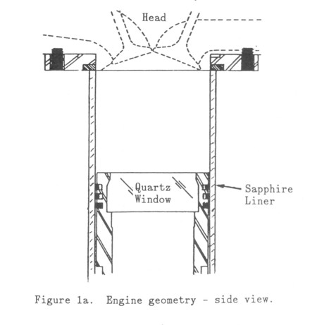
ENGINE - The flame image data of this work were taken from a single-cylinder visualization engine described in detail elsewhere [8,9]. The major characteristics of this engine are representative of a modern-four-stroke spark-ignition internal combustion engine; global parameters for the engine are given in Table 1. The engine has a sapphire liner with a flat quartz piston-top window in an extended piston. Premixed propane and air is drawn through the engine for a firing run from an intake tank of 50 cylinder-volumes.
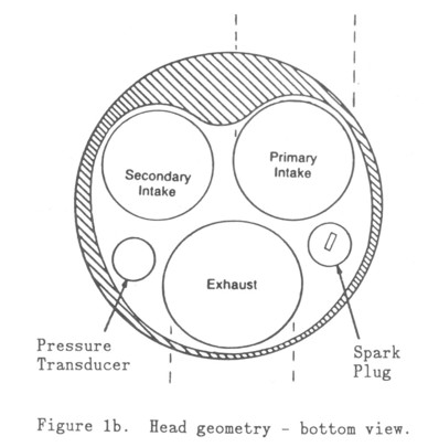
Shown in Figure la is the pent-roof head geometry and the transparent liner that extends to the bottom of the head. Figure lb shows the valve, spark plug, and pressure transducer location in the head. Although the head is designed for two spark plug operation, the secondary plug has been replaced with a pressure transducer for this work. The peripheral spark plug is oriented vertically (parallel to the cylinder axis) and is electrically driven by a standard HEI ignition system. The piston window diameter is 69.8 mm at its smallest section, compared with the 92 mm, cylinder bore. Combustion chamber crevices consist of a 0.6 mm gap 5.0 mm deep around the piston, and a 3 mm deep, 0.1 mm wide gap at the bore radius in the head.
Two basic engine configurations were used. Although both valves operate normally, the secondary port can be throttled at the entrance to the head. This throttle was closed for data referred to as "l-port", resulting in a mean swirl ratio of 1. Data referred to as "2-port" differs from this only with respect to the opening of this throttle plate, giving very little swirl. In all cases the manifold absolute pressure (MAP) was adjusted to 0.75 atm.
FLAME IMAGING DIAGNOSTIC - Flame behavior is studied by analyzing short exposure stereo images of flame luminosity taken by two image-intensified CCD video cameras. The flame imaging system is described in detail elsewhere [8,9]. The cameras have a linear response to visible light and a luminous gain variable up to 20,000. The basic format of a digitized flame image is an array of 512 x 512 pixels, with an 8 bit intensity resolution. Spatial resolution of the images is on the order of a few pixels, limited by the image intensifier resolution, decreasing with increasing gain. Flame images are analyzed by a commercial image processing package on a high-resolution (1024 x 1280), 256 color IBM PC/AT monitor. The images are correlated with pressure data that has been post-processed to give mass burned progress using techniques similar to those described in Rassweiler and Withrow [11].
FLAME IMAGE DATA EXPLANATION - The flame image data presented in this work gives information about both the spatial and temporal structure of the flame. A sample of this data is shown in Figure 2.
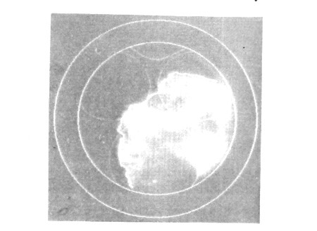
Figure 2. Flame image data sample, bottom view double exposure at 20o BTDC and TDC, 1-port flow, spark at 40° BTDC, øi = 0.75, MAP = 0.75 atm., 500 rpm.
Spatial variation of the intensity of the flame radiation integrated along a line of sight is shown for the bottom view through the piston top. As for most of the figures, a line drawing derived from a reference image shows the background engine geometry, superimposed on the flame image. The line drawing of Figure 2 reflects the geometry shown in Figure 1b, including the valves and spark plug with the electrode at the lower end of the ground strap. The protruding shape between the intake valves is the bottom flat of the head protruding into the window view. These line drawings are added with image processing software for each sequence of cycles without any adjustment of their relative location.
Flame development is recorded during a single cycle at normal engine speeds by making two sequential exposures at different times on one frame, necessitated by the 30 frames/sec standard video framing rates. Single image exposures as short as a few microseconds are obtained by gating the image intensifier. For the case of peripheral ignition described in this work, the early flame (bright patch close to the spark plug in Figure 2) is spatially separated from the flame front at TDC which has moved to a different part of the cylinder. The images in Figure 2 were taken at 20° BTDC and at TDC, each approximately 1° in duration. Since the flame front radiation is much greater than the comparatively uniform and weak radiation from the burned gases, the early and later images can easily be separated in most cases.
A calculated flame front is shown in white at the leading edge of the TDC flame image. This line was derived by threshold processing the image; all pixels below a chosen value are black and the rest are white. Laplacian edge detection then provides a flame edge 1-2 pixels thick, from which obvious noise is removed with the image processing editor. All flame fronts shown in this work have been derived in this way.
ENGINE CONTEXT OF CYCLIC VARIATION
The data and discussion are organized in parallel with the stages of flame development in an engine, described as combustion-progress regimes in the previous work [9]. As combustion proceeds from ignition to extinction in each cycle, effects that enhance or delay combustion combine into many different burn histories. These effects can interact in ways that result in the same mass burned fraction at one point in the cycle but quite different burn development, leading to a great deal of statistical confusion when attempting to establish cause and effect.
Bore: 92.0 mm....................Piston: Extended,Flat-topped
Stroke: 92.0 mm..................Fuel: Propane
Con Rod Length: 191.6 mm.........Spark: Duration - 1.5 ms, Energy - 50mj
Compression Ratio, Cr:9:1..............................
RPM: 4000 max....................Head: Three-Valve, Pent-roof
Table 1. Engine Parameters
Two geometric effects dominate the behavior in this engine: the peripheral spark plug, and the swirl that comes from the port configuration in use. The peripheral spark implies a longer burn across the chamber than a central plug so that for most of the cycle the flame geometry is determined by only the side of the early flame kernel facing the center of the chamber. Also, the spark is more sensitive to swirl near the wall where swirl velocities are higher. The low swirl number for the configurations discussed in this work imply that the in-cylinder flow will in general contain variable large scale motions, rather than a consistent overall rotation of the flow and flame from swirl.
It is important to state that the results discussed are representative single-cycle examples from a much larger set of operating data. Care has been taken to avoid misrepresentation of the whole by the sample.
SPARK CYCLIC VARIATION
In most current spark-ignition automotive engines combustion is initiated by a 1-2 as duration high-voltage inductive arc. Important characteristics of this spark are its energy, location, and duration. The energy of the spark is not important if that energy is well beyond a known threshhold value [13], except possibly for very large energies. A millisecond spark duration has been found to enable the spark plug to act as a source of continuous ignition of the mixture passing by the plug at velocities higher than the initial flame velocity [14]. Spark location, both relative to the combustion chamber (location, protrusion, and strap orientation) [15,16] and relative to the plug itself, especially with respect to the ground strap, is important for the early flame kernel growth. The ground strap is both an obstruction and a heat sink for the newborn flame.
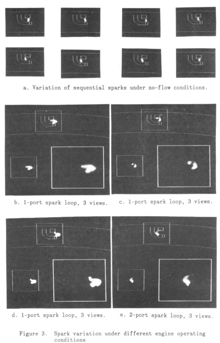
Images taken with a slant view up into the head from a position opposite the spark plug show the spark moving randomly around on the electrode (Figure 3a). Similar motion of a pulsed spark occurs without flow and results in a significant variation of the distance between the spark and the base of the ground strap. The location of the arc on the plug structure and the shadowing of the strap by the flame indicates that the reference image location is accurate compared to the scale of the spark width.
Greater variations in spark location occur as a result of flow, as shown in Figures b-e. In these figures, four sample spark images are each shown three times relative to a reference box: by itself at the bottom left, magnified x2 at the bottom right, and relative to the spark plug at the top. These spark loops are extreme instances taken from a large set of spark images. The spark was initiated at 40° ETD, and a 0.1° long exposure was taken 3.0° later. Looping of the extent shown in Figure 3 occurs for 1-5% of the sparks, while perturbations on the order of the electrode width or larger occur for approximately 20% of the sparks.
This looping of the spark is caused by flow through the gap that carries the low inertia ionized gas column away from its original location. As the arc moves and its channel length increases, the voltage needed to drive the arc increases until it becomes large enough to break down a new arc across the original gap. This characteristic voltage rise and sharp drop is a common characteristic of inductive sparks in engines. Such a concept has been explored as a technique for determining engine general flow parameters [17]. It should be noted that the spark plug indicated in Figure lb does protrude vertically into the head volume, where presumably higher flow velocities exist relative to a plug at the top center of the chamber.
Figures 3b-d show loops from 1-port data in the direction of the mean swirl for this case. Loops in the other direction do not occur in this configuration, although the 1-port data with little or no mean swirl exhibit loops in both directions. Figure 3e shows an example of a loop in the reverse direction from the 1-port data. The actual frequency of occurrence of these loops in the engine cannot be specified from the occurrence of loops in the images. Loop size and direction will fluctuate in time due to the fluctuating flow; loop history cannot be determined by the single view and single exposure time of this data. However, the frequencies cited above are a lower limit. They are more accurate in the Export case because the mean swirl lessens the dispersion in direction of the loop.
The data in Figures 3b-d were taken at 1000 rpm for the 1-port case. Data at 500 rpm show similar trends, keeping the delay angle the same: 3o after spark initiation. At 1000 rpm the time delay is half that at 500 rpm, but velocities scale up by approximately a factor of 2 to give the same behavior in the images. However, there should be twice as many breakdowns at the higher speed and thus a higher effective ignition source size, especially if the flow is constantly changing direction, as in the low-swirl case.
The existence of these loops in an engine implies a consequent variation in the size of the ignition source from cycle to cycle, probably with a resulting variation in initial flame kernel size. Since these loops are always associated with relatively strong flows around the spark plug, only detailed measurements can discover whether the flow or the larger spark are greater contributors to a larger initial flame kernel growth. The data presented here do not have adequate time development information to address the question.
The low frequency of occurrence of the loops does imply that there are many cycles without loops, even compensating for possible loops that are developing or that are out of the plane of view. Assuming that the loops begin to form when the spark is initiated they imply a minimum flow velocity of approximately 5 m/s; a displacement of 3 mm over 3° crankangle at 1000 rpm. This compares with a mean piston speed of 3 m/s and is consistent with in-cylinder turbulence measurements in engines. Given a typical turbulence spectrum of from 400 to 1500 Hz, low velocity periods on the order of the spark duration are frequent, supporting the cyclic variability in spark loops, and thus in effective spark size.
This effective spark size will also vary with spark timing. The voltage needed to break down the gap increases in proportion to the square root of the pressure [17]. Thus the loop length attained before a new breakdown occurs across the gap will increase significantly from 60° BTDC to 30° BTDC, causing a larger cyclic variation in effective spark size for the later spark. A smaller counteracting effect is that in-cylinder velocities decay with time, leading to smaller loops later in the cycle.
EARLY FLAME KERNEL CYCLIC VARIATION
At the present time, changes in the early flame kernel, before there is significant mass burned in the cycle, are thought to account for most cyclic variation in spark-ignition engine combustion [3,16,18]. The two primary causes of variation in this early kernel are thought to be distortion by the local flow and interaction of the flame with the spark plug structure. Other factors in cyclic variation include mixture nonuniformity (which will not be considered in this work) and, for very lean operation, misfires.
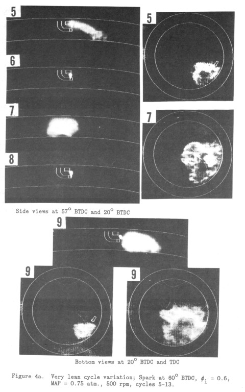
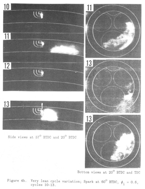
The wide variety of flame behaviors that can occur during very lean operation is illustrated in Figures Barb, which show a sequence of 9 consecutive cycles from a 1-port firing run. For theme cycles the spark was initiated at 60° BTDC, manifold absolute pressure was 0.75 atm. and the intake equivalence ratio, øi, was 0.60. Slant side view exposures were taken at 57° BTDC for a duration of 0.1° and at 20° BTDC for a duration of 2.0°, while bottom view exposures were taken at 20° BTDC for a duration of 2.0° and at TDC for a duration of 1.0°. The images have been enhanced for maximum contrast and the background cylinder patterns have been superimposed. Piston position at 20° BTDC is shown in the side view. Cycle number in the sequence is shown at the upper left. Bottom views were taken for each cycle but are presented only for the cycles with combustion.
The images in Figures 4a-b show a great deal of dispersion in early flame kernel size, shape, and location, but they show very little spark location variation. Flame holding over an extended period is shown in the side view flame image in cycle 5. Flame blowoff is shown by the side view in cycle 11, which is an illustration of flame convection. Both effects have been seen in research engines (e.g. [19]). The flow process of flame stretch is more difficult to demonstrate unambiguously, but cycle 11 also seems to be an example of this, based on the aspect ratio of the flame. The flame development in Cycle 7 indicates that flow velocities have been low throughout the growth of this early kernel.
This set of sequential cycles clearly illustrates the wide variety of mechanisms that give cyclic variation in the early flame kernel. The frequency, or even the existence, of each effect changes in complicated ways with engine configuration and operating condition. The critical parameters are the laminar flame speed, gas expansion velocity, and local flow velocity.
The three-dimensional shape and location of the early kernel are all important for later flame development. A compact flame is shown in cycle 7, while an elongated flame is shown in cycle 11. Given that the early kernel grows in all directions, the flame in cycle 11 will grow much faster than that of cycle 7, resulting in a more rapid early burn phase. Such a correlation is discussed below. Another way of describing this effect in current engine terminology is to say that there is a shorter ignition delay time for the elongated flame. Such terminology is misleading, since the actual phenomenon involves early flame growth rate differences.
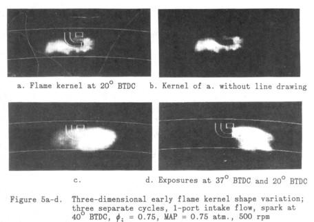
The location of the early kernel is important due to the delaying effect of the spark plug structure. Figure 5 shows the variety of positions taken by the early flame kernel. Figures 5a-b and 5c show the flame behind and in front of the plug, as indicated by the shadow or lack of it in the flame image. Figure 5d shows the flame (and spark) blown to the right of the spark plug. In the 1-port flow in this engine configuration the flame casting the shadow is near the wall and therefore must pass the spark plug again before it fills the chamber. This effect is more important if the clearance space is small or the kernel is still small when it reaches the plug again.
For the spark advances used in this work, the clearance volume is large at the time of early kernel growth, so the location of the early kernel with respect to the spark plug is less important than changes in the kernel size and shape. However, for the previous work [9], when the spark is fired at 5° BTDC the clearance between the piston and spark plug is much smaller, the effect should be evident. This seems to be the cause of the dent in the kernel near the spark plug of some cycles shown in that work.
These flow effects all occur for the 1-port case with a mean swirl ratio of 1. The mean rotation of this flow in any specific cycle, however, varies from approximately zero to more than 1, implying that the mean swirl ratio for such a low swirl number is a misleading indicator of the flow in that particular cycle.
The true misfires shown by the even numbered cycles in Figures 4a-b are complementary data to that discussed in the previous work [9], showing that for late ignition flames exist even though there is no measurable pressure rise from combustion. For similar very lean mixtures, compression of the gas by the piston can make that mixture ignitable. The extreme spark advance of the data in Figures 4a-b begins ignition at much lower pressures and lower temperatures compared with conditions that would occur near TDC.
As an extreme form of cyclic variation the sequence shown in Figure 4 is a sample of an oscillation between true misfires (no flame) and complete burns. This is another case of the residual gas oscillation shown and discussed in the previous work [9]. Air-fuel mixture in the residual gas following a misfire cycle makes the overall mixture rich enough to burn completely in the next cycle, while the situation is reversed following a burned cycle. Such firing conditions can only be maintained in a motored engine because cyclic pressure variation is so severe.
This is a prior cycle effect that has been seen extensively in lean operation in this engine. Partial burns result in stronger burns in the following cycle in general. In real engines such partial burns can occur at any average stoichiometry for a variety of reasons, ranging from spark plug fouling, non-uniform air-fuel charge, to any flame that is slow enough to be quenched by volume expansion arising from piston motion or exhaust valve opening.
MID-CYCLE BURN CYCLIC VARIATION
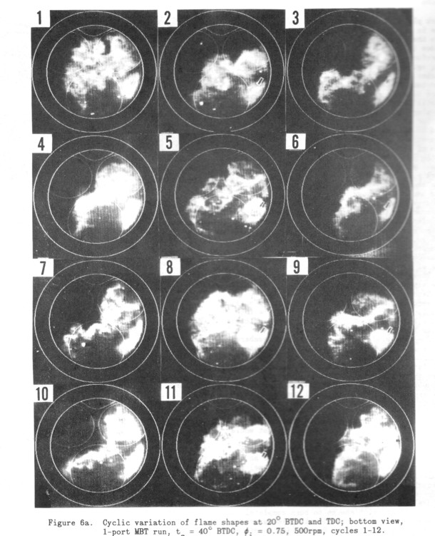
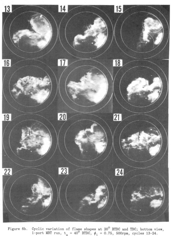
Flame images taken through the piston window of 24 sequential cycles from a 1-port MBT (Minimum spark advance for Best Torque) run at 500 rpm are shown in Figures 6a-b. The spark was initiated at 40° BTDC and the superimposed exposures were taken at 20° BTDC for a duration of 2.0° and at TDC for a duration of 1.0°. The early exposure is shown as the bright part of the image around the spark plug. The engine was operated at an intake equivalence ratio of 0.75, and a MAP of 0.75 atm. MBT timing was indicated by a Mass Burned Fraction (MBF) of approximately 60% at 10° ATDC. As with production engine operation, there is considerable variation around this mean. Simultaneous perpendicular side-view images were also taken through the liner but these were views of the narrow piston clearance volume without a view into the head, and are not presented here.
It should be reiterated that these images represent line-of-sight integrals of the radiation from the flame. Thick flame fronts in the images do not necessarily imply a thick reaction zone. However, at TDC the height of the chamber is much less than its width, so that the major variations in the flame shape at TDC are radial rather than axial. This is not true of the early flame kernel, as discussed previously.
The flame images taken at TDC in Figure 6 show both a broad dispersion in flame shapes-and flame progress. These images show flame shapes that are very similar to those reported in the previous work [9], which were taken at similar conditions except for a very retarded spark. The large-scale shape of the flame fronts in these cycles range from spherical (cycle 1) to flat (cycle 22), to severely indented (cycle 13). The flames tend to be rotated clockwise relative to the location of the spark plug, consistent with the swirl ratio of 1.
The flame shape at TDC is similar to the shape of the side of the early flame kernel facing the main part of the chamber in nearly all of the bottom view flame images taken in the engine. This is a result of the dominance of the gas expansion velocity as a part of the flame propagation velocity. Cyclic variations in the early kernel geometry can thus affect the burn throughout the cycle through the shape similarity, since different large scale flame geometries will result in major variations in overall combustion, as shown below.

Figures 7a-b show 24 sequential cycles of 2-port flame images for conditions identical in other respects to those of Figure 6a-b. Flame shapes are very different, without any flat or indented flames. Combustion progress is slower in general, as indicated by the flame areas, presumably due to a lower turbulent flame velocity from lower turbulence levels. No swirl is indicated, as expected. Once again there is shape similarity between the early and later flames so that the flame shape throughout most of the cycle is determined by the effects that caused the shape of the early flame kernel.
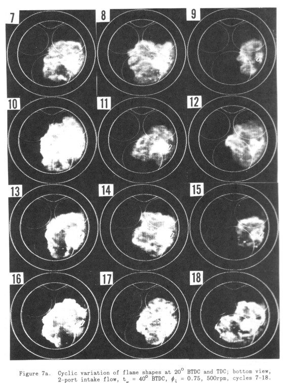
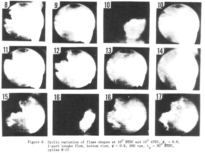
Given the prominence of this apparent flow effect on the flame, engine operation was changed to find out how the flame shapes were affected. In Figures 8a-b flame shapes are shown for an increased intake equivalence ratio of 0.90. Spark timing is 30° BTDC and the exposures occur at 20o BTDC and TDC, as before.
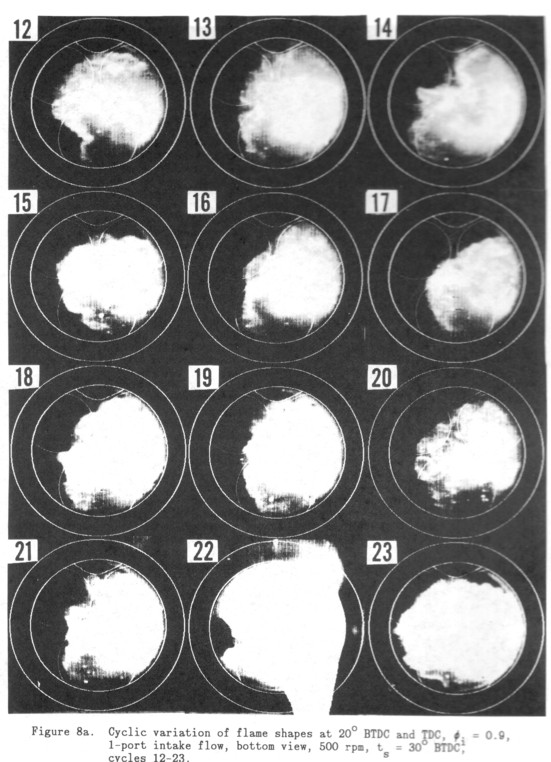
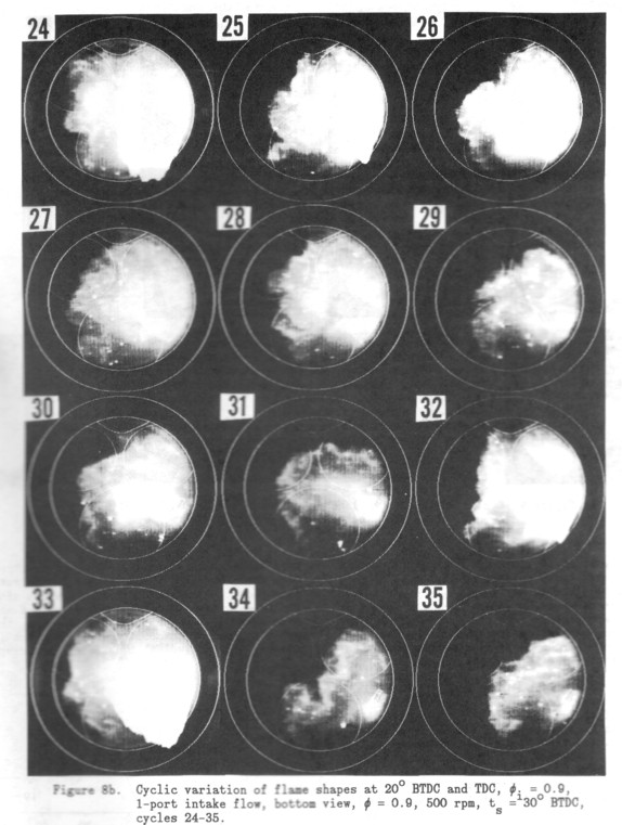
As expected, these images show mostly round flame fronts, because both the laminar flame speed has significantly increased relative to the in-cylinder flow velocities. Camera saturation leading to vertical blooming causes the bright distortions such as that seen at the lower right in cycle 22. There is evidence of the presence of the secondary flow at a reduced level, seen in cycles 14, 22, and 34. The reduced effect of the flow is well known statistically [7]; cyclic variation is reduced as the mixture more closely approaches stoichiometric.
Figure 9 shows flame images from consecutive cycles taken at identical engine conditions as the data of Figures 8a-b, except that the exposures were delayed 10° to be at 10° BTDC and 10° ATDC. For cycles 10 and 16 the early and later images are shown separately, since they happened to fall on either side of a video frame time boundary. Although the flames have often progressed beyond the view of the piston window, cycles 8, 11, 12, and 15 definitely show the indentation characteristic of the secondary flow so prominent in leaner mixtures. This shows that the flow effect is still present, but it occurs later in the cycle and has a reduced effect on the flame shape. That the flow field in the unburned fluid is compressed in front of the flame by burned gas expansion behind the flame has been shown (Witze [20]). These flows can affect flame shape and mass burned in the cycle even at near-stoichiometric mixtures because while the effect occurs late in the volume burned history, it occurs for the middle and late stages of the mass burned history.
As an incidental point of interest, the bright spots in the images are caused by some unknown particle or drop inside the volume of the chamber, usually behind the flame front. Because the engine uses gaseous fuel and has no oil behind its compression rings, there is no obvious explanation for their presence in the images. There is also no evidence of oil leaking through the valve guides.
MASS BURNED CORRELATIONS - Such a large dispersion in flame shape as seen in Figures 6a-b would be expected to cause related changes in MBF history. Flame areas derived from flame images such as those presented here imply mass burned rates, and individual cycle MBF's have long been analyzed in this way [6,11]. Although unique flame shapes such as that of cycle 13 might be expected to result in a unique MBF shape, this was not the case. Initial attempts at correlating flame shape and MBF failed.
To discover more subtle correlations, MBF curves were classified relative to an Beverages cycle, taken to be cycle 9, shown in Figure 2. Combustion progress was catalogued as having early, average, or late timing relative to the average cycle at 1%, 50%, and 90% MBF. The data of the cycles shown in Figures 6a-b were then examined to discover any relationships between flame size or shape, and mass burned progress.
One important correlation that could be identified was that cycles whose early flame kernels were larger correspond to those cycles with an early rise in mass burned. Cycles 7,10,13,14,16,17 and 19 have large early kernels as seen by the bright region around the spark plug. Compare, for instance, the early flame kernels of cycle 6 and cycle 7. The sizes implied in Figures 6a-b can be ambiguous due to the restricted view through the piston window, but the simultaneous side view through the sapphire was used to confirm the extent of these early flame kernels, while eliminating Cycle 8 because it did not extend to the cylinder wall. The correlation was 1 to 1: early rise in MBF occurs if and only if there was a large early flame kernel. MBF curves for two of these cycles are shown compared with the average cycle in Figure 10.
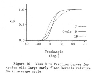
This correlation is necessarily true at the instant that the flame image is recorded, because the volume of the kernel is a measure of the mass burned at that time. However, while these images were taken at negligible mass burned fraction, they correlate with a larger mass burned rate throughout the early stage of combustion after the images were taken. This implies that whatever subsequent combustion effects exist, they are of second order compared to the effect (presumably the local flow) that causes the dispersion in the very early flame kernel size.
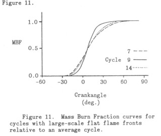
Another major correlation that became apparent was that cycles with flat flame fronts across the cylinder have lower mass burning rates than those with round flame fronts. This is seen in the MBF curve shape as a decreased slope and continually delayed timing with respect to the average. Cycles 3,4,7,10,14,19,22,and 23 are such cycles, once again using the side view to sort out potential candidates. This correlation was also 1 to 1: the mass burned rate is slower throughout the cycle if and only if the flame front is flat. MBF curves for sample cycles relative to the average cycle are shown in Figure 11.
These two effects combine when present together to confuse any global statistics. Some of the large early kernels result in flat later flames. These flames are early relative to the average cycle at the start of significant mass burned, and late at the end of the mass burned, as shown by Cycle 7 in Figure 10. The unusual shape of Cycle 13 is seen to be early throughout the cycle relative to the average cycle, presumably because the flow distortion has caused the flame to grow in two separate large sections, resulting in a larger total burning rate.
Combining these effects with the fact that the shape of the early flame kernel usually determines the shape of the mid-cycle flame, it can be concluded that the shape of the side of the kernel facing the main part of the chamber will determine whether the flame develops as a flat or round flame. This can be seen to be mostly true by examining the small and bright early flame kernels from the first exposure of the images of Figure 6a-b. That this is not uniformly true is due to the influence of strong secondary flows of the scale of the chamber as shown in cycle 13, and discussed below.
FLAME FRONT ANALYSIS - To further explore the flame shapes in the flame images, flame front locations were derived by assuming the flame to begin at a fixed intensity level in the images. Since the flame edges are usually sharp, a change in threshhold level moves the front slightly, but does not change its basic shape. These are not actual flame front loci, but the sum of all of the axially varying protrusions that occur. This would lead to ambiguity for any detained conclusions, but probably does not change the perception of overall shape, because the flames are basically axial. The spark is not high above the piston, resulting in flames that reach the piston early in their history and then quickly lose their axial curvature.
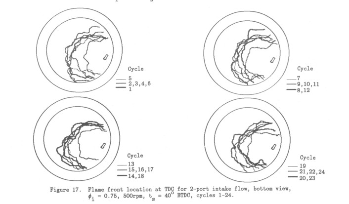
The illustrations shown in this paper are significantly degraded from those used in data analysis. The original flame images used to derive the flame fronts are of clearly better quality. For a few of the flame fronts the original image was used to complete the locus of the front, where the background light prevented accurate threshholding in part of the image. The flame fronts shown in Figures 13-18 are presented using three different line widths to show the flame fronts for up to six cycles, leading to some confusion of the individual flame fronts. The original analysis was done by assigning each flame front a primary color; each one of the superimposed six flame fronts was easily distinguished and could be manipulated separately using its color index.
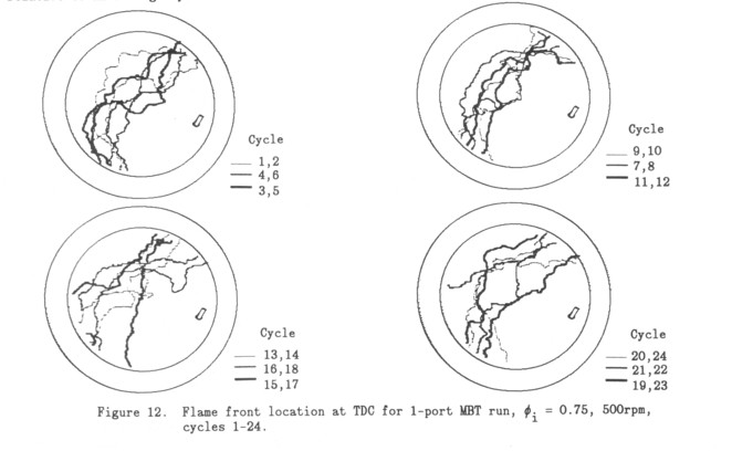
For the 1-port case, flame fronts were derived from the images shown in Figures 6a-b, and are given in Figure 12 together with the outlines of the spark plug ground strap, the cylinder bore, and the piston window border. The cylinder pattern location is accurate to approximately the scale of the line-widths used.
The 24 cycles of Figure 12 show a band of flame front locations that might represent the cyclic variation of combustion at these conditions. However, since the MBF arises from the volume enclosed by the flame, very different shapes imply the same mass burned. Note that the MBF at TDC is 25-30% (Figures 10 and 11) whereas the volume burned is 50-60%.
The effect of the mean swirl can be removed to better compare the flame shapes in different cycles. This image analysis assumes solid body rotation about the axis of the cylinder. A line is drawn through the flame front so that the area between the flame front and the line on either side of the line are estimated to be equal. The slope of this line relative to a line bisecting the cylinder and passing through the spark electrode was used to give a rotation angle of the flame relative to a spherical expansion from the spark electrode. The flame fronts were then rotated back through this angle so that each one appears to have expanded from the spark plug.
The apparent dispersion of flame front location is significantly reduced by this processing, and these images are a better representation of the real MBF dispersion. In order to examine the question of the relative speed of round vs. flat flames, these flame fronts were sorted by shape. The sorting was done on the qualitative basis of how well their shape approximated a circular arc with its center at the spark plug, or whether the shape showed the characteristic central indentation toward the spark plug. Cycles that did not fit well in either category were classified as "intermediate".
Figures 13a-d shows the result of this sorting. Figures 13a shows a set of round flames with very small location dispersion, while Figure 13b shows indented shapes, also with very small dispersion. The indented shape became apparent when the flatter flames were grouped together. Figures 13c-d show the remainder of the flame fronts, whose shape seemed to be intermediate between the round and indented shape.
The groups form three nearly equal sets, and the very small dispersion of the round and indented sets very strongly implies the existence of a bistability in shape. This is presumably due to an unstable large-scale secondary flow in the cylinder. The indented flames indicate its presence, while the round flames imply flame development when this flow is not in the cylinder. The effect of the flow varies in strength, but is most prominent in cycle 13. This phenomenon was previously seen for similar conditions with late firing in the previous work [a].
From this grouping of cycles, the relative burn rates of round vs. flat flames can be assessed quantitatively, as shown in Figure 14. Peak burn rate was derived by differentiating MBF data, derived from pressure data, and plotting the maximum. The peak burn of the cycle was chosen rather than the fraction burned at a particular time to lessen the influence of cycle phasing on the burn rate correlation with the different flame shapes.
The results in Figure 14 show that round flames have significantly higher peak burn rates than flatter flames, The question mark for cycle 21 indicates that the flame shape at TDC could not be determined because the flame front extended beyond the view of the piston window.
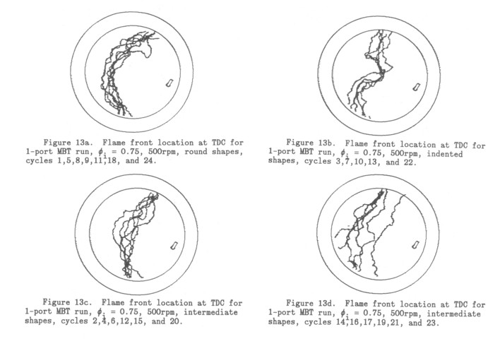
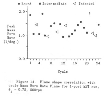
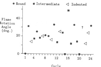
Figure 15. Flame shape correlation with cycle swirl angle for 1-port MBT run, øi = 0.75, 500 rpm.
However, it is almost certainly round, as indicated by the shape of the early flame kernel, consistent with the burn rate correlation. Further confirmation of the correlation is that cycles 3 and 13 are extremely dented, to form two separate essentially round flames so that the cycle as a whole has a higher burn rate.
The cause for the higher burn rate of the round flames is that for a flame propagating normal to its surface, a circular flame increases its area with time, whereas the area for the flat flames remains constant. This is a simple geometric argument supported by the data of Figure 14. The implication of this fact is that the smaller scale wrinkling of the turbulent flame, while it is certainly present, is relatively constant from cycle to cycle. A major cause of cyclic variability for this engine configuration at these operating conditions is an unstable large-scale secondary flow.
An alternate possibility as a cause for such distorted flames might be non-uniform mixing of residual gases. The intake fuel and air in this experiment are extremely well mixed, supplied to the intake tank by sonic orifices through an L/D > 100 tube. To eliminate the possibility of residual effects, the engine was fired on alternate cycles at a reduced intake equivalence ratio to give the same pressure release. No change was seen in the flame shapes.
To learn whether the flame shapes (and thus the secondary flow) are somehow connected with the swirl in each cycle, the swirl angles used to derive the corrected flame fronts are plotted in Figure 15. No correlation emerges. The data are consistent with the average swirl ratio of 1, but there are three cycles without any indication of swirl. Even though there is mean directed flow from the placement of the intake duct, this does not necessarily result in swirl, another indication that mean swirl numbers up to 1 are a misleading descriptor of the detailed flow.
Engine speed was another change made in operating condition to explore flame shapes. Flame images were taken at 1000 rpm at the same conditions as those for the flame images of Figures Barb. Flame front locations were derived as before, and then corrected for swirl, as before, with results presented in Figure 16.
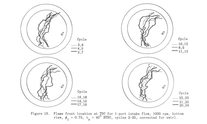
As can be seen in the flame front data, the bearable flame shapes have almost entirely disappeared. Replacing the two shapes is an intermediate shape, so that the average remains the same while the dispersion has decreased. These flow and flame changes with rpm would thus not appear in a global statistical analysis of the cycles based on heat release.
A fundamentally different flow in the engine occurs during Export operation. The pressure drop across the valves is much lower, as are the intake velocities, and there is also no significant swirl.
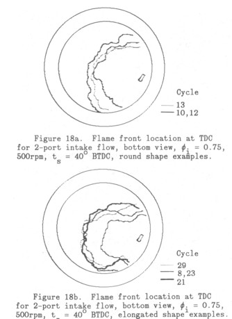
Figure 17 shows the flame fronts derived from the images of the 2-port, øi = 0.75, 500 rpm, case shown in Figures 7a-b, and these possess significant dispersion. The shapes of these fronts suggest another sorting such as was done above, this time into elongated and round flame fronts as shown in the examples in Figures Arab. The sorting is not so effective as in the previous case, but it does seem to again imply a bistability between round flames and elongated flames. It should be noted that the elongation is aligned with the pentroof, and is consistent with preferential expansion of the flame along the direction of greatest area. The round flames seem to have some clockwise swirl, probably preventing the alignment of the flame expansion with the pentroof axis. The importance of the effect of large-scale unstable secondary flows seems to be reinforced by this data.
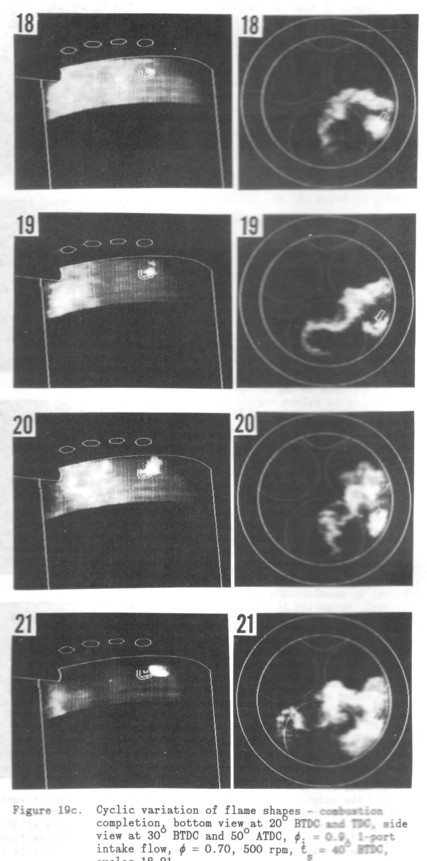
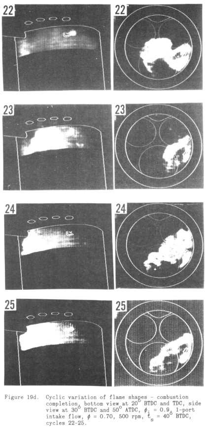
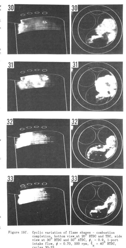
The flame variation that is characteristic of Export operation at 500 rpm in this engine can be seen in the bottom view images. These images show flame front variation under leaner conditions than discussed above, and support the flow-flame interaction conclusions already drawn from the data.
The side view images of combustion in each cycle show the location of continuing combustion at the wall. Fully burned regions result in uniform intensity, while radiation from the burning turbulent flame gives regions of highly structured intensity. The faint striations aligned with the piston-top line are caused by compression ring debris on the inner wall.
The shape and progress of the flame shown in the bottom view at TDC, results in large differences in the size of the regions of continuing combustion along the wall 50° later in the cycle. Since the spark is opposite the view of the camera taking the side view images, these images show the burning flame area as the flame approaches the wall. Combustion is complete at 50o ATDC in cycles 10 and 17; in cycle 10, this is due to the relatively greater progress of burning, compared to other cycles, but in cycle 17 combustion is completed because the flame shape happens to closely conform to the shape of the chamber when it reaches the wall. The flatter flames of cycle 13, 19, 24, and 25 cause longer combustion durations compared to the rounder flames due to the flame-chamber shape mismatch, even though the flame areas are comparable at TDC. This effect adds to the slower burning rate of the flatter flames to give even larger cyclic dispersion between flat and round flames.

The degree to which the flame shape conforms to the combustion chamber shape is another major cause of cyclic variation. It is one that should be nearly as important for central ignition as for peripheral ignition due to flow distortion of the early kernel shape and the constancy of that shape.
Another cause for cyclic variation can be identified as axial variations of flame shape. Almost all of the side-view images indicate that the flame front is vertical, supporting the earlier assumption that the bottom view images are good representations of flame shape even though they are axial averages. However, cycle 23 shows significant slope to the flame front and thus a longer time to complete combustion. As with all of the other effects causing cyclic variation this will increase the statistical dispersion of the cycles, although in any particular cycle it may not cause delayed combustion compared with the average cycle, depending on prior events.
It is interesting to note the variations of the very early flame kernel that are shown in the side view in the combustion completion images. While most of the kernels are displaced to the right, in the direction of the mean swirl, the flame images for cycle 25 show the kernel developing between the spark plug and the wall. This is consistent with the above results concerning the dispersion in the shape and location of the early flame kernel. Cycle 25 presumably is a case where the early kernel is blown toward the wall, and is stretched out because of flow divergence there, leading to the flat flame that later develops.

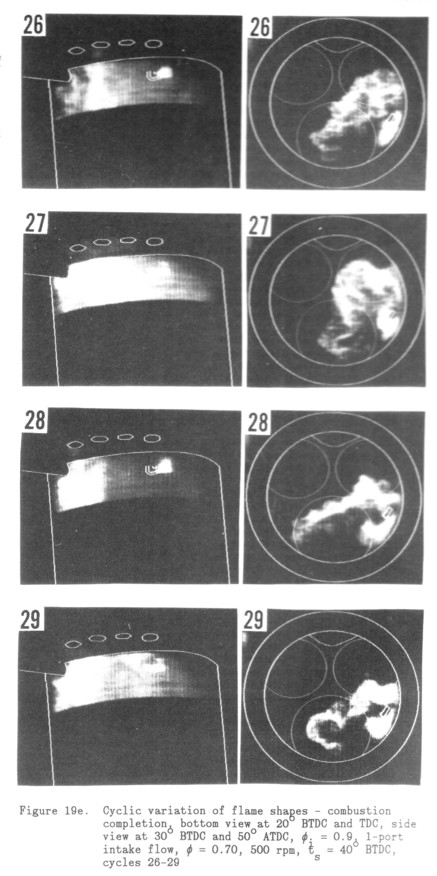
A striking aspect of the side view images is that the intensity structure scale is very uniform from cycle to cycle. This is surprising because there is such a large variation in overall shape and large scale flow between cycles. Apparently the turbulence at these scales varies little, which is consistent with the correlation discussed above that indicates that large scale changes in flame shape account for the primary changes in overall flame area for most of the cycle. Similar length scales have been found with particle imaging velocimetry in an engine by Reuss et. al. [21].
COMPARISON WITH PREVIOUS RESEARCH
It is appropriate to briefly discuss how the results presented in this work interleave with some relevant previous research.
The recurring theme (e.g.[22]) of the usefulness of decreasing overall combustion time to reduce cyclic variability has interfered with the identification of the fundamental causes of cyclic variation. Massive regression analyses have been performed on engine operating statistics to relate engine parameters to cyclic variation [7]. Such studies show that absolute cyclic variability can be lessened by finding the means to concentrate pressure release more near TDC. However, the causes of cyclic variation result in a relative dispersion of combustion duration compared with the mean, and this relative dispersion may increase or decrease as the combustion duration is shortened. An example is to assess a parameter such as equivalence ratio, which has its major effect on cyclic variability by accelerating combustion in general, primarily through an increase in laminar flame speed [23,24]. However, the higher equivalence ratio may be concentrating the cyclic variation at the end of the cycle where engine performance can be degraded by knock.
Another significant part of previous work on cyclic variability depends on the use of ionization gap measurement of flame progress [1]. These measurements are only reliable for spherical flames, and this work shows that such flames do not occur in general for lean mixtures or beyond the midpoint of volume combustion. For example, in two consecutive cycles with a flat, then a round flame, an ionization gap measurement taken opposite a peripheral plug ignition would indicate a spuriously low flame speed for the flat flame. Ionization gap work may often be misleading based on 3-dimensional flame shape variations, and must be evaluated carefully.
Cyclic variation was originally associated with the variability of cycle pressure release (e.g. [25]). The approach of studying combustion progress by analyzing cycle pressure history has been deliberately avoided in this work. The causes of cyclic variation have been found to be such that each one gives a separate dispersion in combustion progress, combining to result in a dispersion in combustion phasing whose cause will often be nearly impossible to unfold from statistical analyses of cycle pressure measurements.
Flow in the cylinder is generally accepted to be the primary cause of cyclic variation in engines, but only by inference, due to a lack of measurements [1]. For the problem of in-cylinder flow, the boundaries are predetermined, if not fixed, and the decaying turbulence has a particular kind of initiation in terms of energy, duration, and geometry. This leads to repeatable characteristics of the flow, such as mean swirl and turbulence level. The primary effect of the flow is thought to be through the variation in the early flame kernel (e.g. [2,3,16,181). This is confirmed by the present work, identifying the cause primarily as the determination of the size and shape of the early kernel, which usually determines the shape of the later flame and consequent geometric effects on burn rate.
A number of effects have lead to confusion in the isolation of the causes of cyclic variability in the early flame kernel and later in the cycle. The work of zur Love and Braces [26] has revealed some new characteristics of engine turbulent combustion, but since each image was taken in a different cycle, limited information can be deduced about flame development in each cycle or cyclic variability. The work of Keck et. al. [16], while clearly showing the variation in 3-dimensional early flame kernel size, shape, and location similar to that shown here, employs an square engine geometry (and lower compression ratio) that must change the flow fields in major ways. A spherical flame expansion model is forced onto a flame that was shown have large changes in aspect ratio. While flame shape similarity between the early and later flames can be seen in many flame images in the literature [e.g. 33] it is often masked by 3-dimensional effects and when the flame is nearly spherical.
Current experimental work [27,28] has also identified secondary flows called tumble, that seem to make predictable contributions to turbulence characteristics at TH. Such flows are highly suggestive of the bearable, large-scale flows discussed in this work. Both of these effects are seen in a similar form and used as simple combustion quality diagnostics using flame imaging in a manner much like the present work by Nakamura et. al. [29]. This and other evidence indicate that small scale turbulence need not be the major contributor to cyclic variation, as has been claimed [5].
Engine speed variations have been found to have a mixture of effects on cyclic variability [1], although increased turbulence with speed would be expected to increase cyclic variability through greater variation in the flow when the early flame kernel is growing. The disappearance of unstable secondary flows at higher speeds may be one effect that causes the cyclic variability to decrease with speed.
The effect of residual gases on cyclic variability has been studied by a number of authors [30,31,32]. Statistical studies of sets of engine cycles do indicate some prior-cycle dependence at very lean conditions [30]. These cycle conditions involve slow flames and long combustion times compared with stoichiometric conditions. These are conditions where one would expect a significant number of partial burns, lending support to the effect of partial burns seen so often in lean combustion in this engine. A combustion instability arising from the interaction of laminar flame speed and combustion duration with exhaust temperature and residual fraction has not been observed. Such an effect has been proposed [31,32], but is at least obscured by other more obvious effects.
The need for the flame to conform to the combustion chamber is well known (e.g. [33,34]); it is a basic rule in current engine design. The interaction of variable flame location and shape with chamber shape is also known (e.g. [2,29]), but since there is currently no way to control flame positioning, little work has been done on this aspect of cyclic variability.
CONCLUSIONS
The data presented and discussed above lead to a variety of conclusions about the nature and causes of cycle-by-cycle variation in SI four stroke engines.
1) Demonstrated causes of cyclic combustion variation:
i) A faster burn rate throughout the early stages of combustion correlates with the size of the very early flame kernel; earlier rise of the MBF occurs if and only if there is a large very early flame kernel. These early flame kernels are larger at negligible MBF, indicating that the important mechanism that causes the larger relative size occurs very soon after flame initiation and is not overcome by other later effects in the first part of the burn.
ii) The early flame kernel is usually shaped by the local flow, causing large variations in kernel size, shape, and location, and consequent variation in combustion through the control of the later flame geometry by the geometry of the early kernel.
iii) Flame shape is usually self-similar as the flame grows after the early flame kernel stage, modified by wall-interaction effects.
iv) Flat flame fronts have a lower mass burned rate than circular flame fronts, and cause relative combustion progress delays. These flat flames arise both from distortion of the early flame kernel and from interaction of the flame with large scale flows. The change between flatter and rounder flames is a major cause of overall cyclic variation of combustion
v) Changes in the dares to which the mid-cycle flame shape conforms to the combustion chamber shape is another major cause of cyclic variation. Major differences in the distance between the flame front and the wall around the circumference of the flame cause a dispersion in a combustion duration due to the differences in the necessary flame travel time before combustion completion. This is a factor that should be nearly as important for central ignition as for peripheral ignition, due to flow distortion of the early kernel shape and the constancy of that shape.
vi) Another cause for cyclic variation can be identified as axial variations of flame shape. This is a comparatively rare event that also causes combustion delay because the flame shape does not conform to the combustion chamber axially.
vii) For Export operation in this engine at 500 rpm, major cyclic dispersion is characterized by flame front shapes that arise from 2 basic shapes that themselves have much less dispersion: round and indented. The existence of this separation strongly implies a bearable largescale flow in the cylinder.
viii) The lean combustion oscillation found in earlier experiments [9] also occurs at advanced spark timing; cycles alternate between complete combustion and total misfires.
ix) Partial burns that cause stronger burns in the following cycle are significant causes of cyclic variation in lean combustion.
2) Probable causes of cyclic variation - phases of combustion with demonstrated cyclic variation:
i) The existence of looping of the spark away from the plug gap causes an apparent cyclic variation in the ignition source size. The spark loops are caused by local flow through the spark plug gap and can be used to estimate that flow velocity.
3) Conditions demonstrated to affect cyclic variation of combustion:
i) The unstable large-scale secondary flows disappear at 1000 rpm, where the average flame shape becomes that seen in each cycle. This is important evidence of a fundamental change in flow and combustion behavior with engine speed.
ii) For equivalence ratios approaching stoichiometric the large scale secondary flows affect flame development much less. However, these flows do become important again late in the combustion event.
iii) The cyclic variations of combustion caused by the interaction between the flow and the flame are magnified by peripheral ignition. This is due to the long flame travel required to complete combustion, one-sided flames, and the early interaction with the chamber wall.
4) Miscellaneous conclusions:
i) Relative mass burning rates between cycles correlate quantitatively with whether the large scale flame shape is round or flat.
ii) Low swirl numbers may be a misleading descriptor of the flow, since the mean rotation of this flow in any particular cycle varies from approximately nothing to more than that indicated by the swirl ratio.
iii) In this engine configuration there is significantly less variation in flame shape and flame speed during 2-port operation compared with 1-port operation.
iv) The spark plug functions as a flame holder at low swirl ratios, except for very lean mixtures when blown-off flames sometimes do occur.
ACKNOWLEDGEMENTS
Numerous discussions with Rod Bask on the various implications of the flame image data were very helpful. Group meetings with interested staff members of the Fluid Mechanics Department and the Engine Research Department also provided useful criticism and discussion.
REFERENCES
1. M. B. Young, "Cyclic Dispersion in the Homogeneous Charge Spark-Ignition Engine - A Literature Survey," SAE Paper 810020, 1981.
2. F. A. Matekunas, "Modes and Measures of Cyclic Combustion Variability," SAE Paper 830337, 1983.
3. G. T. Kalghatgi, "Spark Ignition, Early Flame Development and Cyclic Variation in I. C. Engines," SAE Paper 870163, 1987.
4. M. R. Belmont, M. S. Hancock, and D. J. Buckingham, "Statistical Aspects of Cyclic Variability," SAE Paper 860324, 1986.
5. P. G. Hill, "Cyclic Variations and Turbulence Structure in Spark-Ignition Engines," Combustion and Flame, Vol. 72, 1988, pp. 73-89.
6. Taylor, Charles F., "The Internal-Combustion Engine in Theory and Practice," Second Edition, MIT Press, Cambridge, MA, 1985, Vol. III
7. M. B. Young, "Cyclic Dispersion - Some Quantitative Cause-and-Effect Relationships," SAE Paper 800459, 1980.
8. Bates, Stephen C., "Flame Imaging Studies in a Spark-Ignition Four-Stroke Internal Combustion Optical Engine," SAE Paper 890154, 1989.
9. Bates, Stephen C., "A Transparent Engine for Flow and Combustion Visualization Studies," SAE Paper 880520, 1988.
10. F. W. Schipperijn, R. Nagasaka, and R. F. Sawyer, "Imaging of Engine Flow and Combustion Processes," SAE Paper 881631, 1988.
11. G. M. Rassweiler, and L. Withrow, "Motion Pictures of Engine Flames Correlated with Pressure Cards," SAE Transactions, Vol. 42, No. 5, pp. 185-204, 1938.
12. Bates, Stephen C., "A Displaced-line Velocity Diagnostic and its Application in a Visualization Engine," Experiments in Fluids, Vol. 7, No. 5, 1989, pp. 335-343.
13. G. C. De Scale, "Propagation Behavior of Spark Ignited Flames in Early Stages," Into Conf. on Combustion, Vol. I, I. Mach. E., 1983-3, Paper C59/83, 1983, pp. 93-100.
14. P. 0. Wetzel "The Effect of Spark Location on Combustion in a Variable-Swirl Engine," SAE Paper 820044, 1982.
15. J. N. Mattawan "Effects of Combustion Chamber Design on Combustion in Spark Ignition Engines," SAE Paper 821578, 1982.
16. J. C. Keck, J. B. Heywood, and G. Noakes "Early Flame Development and Burning Rates in Spark Ignition Engines and Their Cyclic Variability," SAE Paper 870164, 1987.
17.R. Maly, H. Memel, and E. Wagner, "Novel Method for Determining General Flow Parameters from Conventional Spark Discharges," Into Conf. on Combustion, I. Mach. E., 1983-3, Paper C67/83, 1983
18. R. K. Barton, S. S. Lestz, and W. E. Meyer, "An Empirical Model for Correlating Cycleby-Cycle Cylinder Gas Motion and Combustion Variations of a Spark Ignition Engine," SAE Paper 710163, 1971.
19. R. Hermes, P. Begleris, A. Zettlitz, and G. F. W. Ziegler, "Flow Field Effects on Flame Kernel Formation in a Spark-Ignition Engine," SAE Paper 881639, 1988.
20. D. E. Foster, and P. 0. Wetzel "Velocity Measurements in the Wall Boundary Layer of a Spark-Ignited Research Engine," SAE Paper 872105, 1987.
21. D. L. Reuss, R. J. Adrian, C. C. Landreth, D. T. French, and T. D. Fansler, "Instantaneous Planar Measurements of Velocity and Large-Scale Vorticity and Strain Rate in an Engine Using ParticleImage Velocimetry,' SAE Paper 890616, 1989.
22. H. Kuroda, Y. Nakajima, K. Sugihara, Y. Takagi, and S. Muranaka, "The Fast Burn with Heavy BAR, New Approach for Low NO x and Improved Fuel Economy," SAE Paper 780006, 1978.
23. M. Metghalchi, and J. C. Keck, "Laminar Burning Velocity of Propane-Air Mixtures at High Temperature and Pressure," Combustion and Flame, 38, pp. 143-154, 1980.
24. M. Metghalchi, and J. C. Keck, "Burning Velocities of Mixtures of Air with Methanol, Isooctane, and Indolene at High Temperature and Pressure," Combustion and Flame, 48, pp. 191-210, 1982.
25. D. J. Patterson, Pressure Variations, a Fundamental Combustion Problem," SAE Paper 660129, 1966.
26. A. 0. zur Love and F. V. Braces, "TwoDimensional Visualization of Premixed-Charge Flame Structure in an IC Engines SAE Paper 870454, 1987.
27. C. Verities, G. Vorropoulos, and J. H. Whitelaw, "Effects of Intake Port and Combustion Chamber Geometry on In-Cylinder Turbulence in a Motored Reciprocating Engine," Fluid Flow and Heat Transfer in Reciprocating Machinery, ASME Publication FED-VOL. 62, 1987, p. 9-16.
28. S. Henriot, J. F. Le Coz, and P. Panchen, "Three Dimensional Modelling of Flow and Turbulence in a Four-Valve Spark Ignition Engine - Comparison with LDV Measurements," SAE Paper 890843, 1989.
29. A. Nakamura, K. Ishii, and T. Sasaki, "Application of Image Converter Camera to Measure Flame Propagation in Sol. Engine," SAE Paper 890322, 1989.
30. J. K. Martin, S. L. Plee, and D. J. Remboski, Jr., "Burn Modes and Prior Cycle Effects on Cyclic Variations in Lean-Burn Spark-Tgnition Engine Combustion," SAE Paper 880201, 1988.
31. J. W. Daily, "Cycle-To-Cycle Variations: A Chaotic Process?," SAE Paper 870165, 1987.
32. J. C. Kantor, "A Dynamical Instability of Spark Ignition Engines," Science, Volume 224, pp. 1233-1235, 1984.
33. J. A. Mattawan E. G. Groff, and F. A. Matekunas, "Turbulence, Flame Motion and Combustion Chamber Geometry - Their Interactions in a Lean-Combustion Engine, Paper c100/79, I. Mach. E. Conference on Fuel Economy and Emissions of Lean Burn Engines, London, June 1979.
34. E. G. Groff, and F. A. Matekunas, "The Nature of Turbulent Flame Propagation in a Homogeneous Spark-Ignited Engine," SAE Paper 800133, 1980.