CRYOSTABILIZED ENERGETIC CHEMICAL PROPELLANTS
Stephen C. Bates, President
Thoughtventions Unlimited LLC, 40 Nutmeg Lane, Glastonbury, CT
thought@Thoughtventions.com www.Thoughtventions.com
ABSTRACT
There exists a set of high energy materials that can be cryogenically stabilized and used to provide revolutionary improvements in chemical propulsion. Paths to the production of these cryostabilized propellants (CSPs) include 1) Condensation of pure gases to form stable cryosolids, 2) Seeding common cryosolids (e.g. H2 or O2) with isolated energetic species, and 3) the formation of atmospheric pressure cryogenic solid van der Waals compounds. Associated ancillary techniques that must be developed include: 1) Formation of CSP slushes, 2) Forming CSP's for propellant use (hybrid rockets), 3) Epitaxial cryosolid growth, and 4) Concentration or separation techniques for cryostabilized additives. Furthermore, advances in stability specification and practical environment control are required; in particular detailed multiparameter instability thresholds, stability testing methods, and materials handling advances are needed - defining instability by hammer impact is insufficient. This needed work is dominated by engineering using the most modern techniques.
INTRODUCTION
The history of practical advances in chemical propulsion over the past 50 years is highlighted by advances in materials, hardware fabrication, and device efficiency, but not chemical propellants. The fuels used today in chemical propulsion are essentially those of the past, except for a movement to more environmentally friendly green fuels. There have been a number of efforts to develop more energetic fuels than the gold standard of LH2/LO2, but these efforts, in particular the Air Force's High Energy Density Material (HEDM) Program, have not produced practical results. These failures have discredited chemical propulsion research to the extent that it has been many years since significant research has been performed, and there are few researchers left in the field. To attend the Joint Propulsion Conference is to be forced to focus on space propulsion, with a hopeful, but minor effort in scramjet propulsion.
It is tempting to assume that everything possible in chemical combustion has already been tried and found wanting. However, concepts that have been ruled impractical in the past are no longer so. Liquid ozone is unstable in the presence of 20 ppm of hydrocarbon contaminants [1]. Work performed through the 1950s was done when these impurity levels were difficult, if not impossible to detect or eliminate; now materials and detection techniques are concerned with ppb or less. These days, atomic detection and manipulation is possible; tremendous advances have been made in the preparation of nanomaterials and their properties. Broad advances have been made in cryogenics engineering. A wide variety of novel approaches are now available that make materials that were considered to be impractical in the past to be standard practice in the near future. Only research dollars are needed. There has been much theoretical and laboratory work done in the past 20 years; now engineering work is needed.
Dr. Stephen C. Bates has been working in the field of cryostabilized propellants since 1990. He has obtained minor funding from the AF HEDM program [2], [3] and NASA [4], for related work, has published a series of AIAA papers [5-7], other papers [8],[9], and a patent [10] on the subject, and has performed extensive unfunded work, some of which is described below. He has developed advanced concepts in cryostorage, solid cryogen radiation shielding, and cryoheat transfer. At Thoughtventions Unlimited he has built up unusual cryogenic resources for a small company, only limited by funding. The work described below has been funded primarily by Thoughtventions.
CRYOSTABILIZED PURE PROPELLANTS
There appear to be at least two cryostabilized pure propellants - solid ozone (O3) and solid HO2; solid O3 is by far the best near-term candidate for a practical CSP. It seems likely that there are other chemical possibilities, given the properties and behavior of solid ozone. Solid acetylene also appears interesting.
Ozone
Liquid ozone as a fuel has been studied because of its large energy of formation since the 1940's, beginning in Germany. Calculations have shown that 50 mole % ozone in oxygen would increase the Isp to 410 sec, a 20 sec increase compared to solid O2/H2 combustion [11]. Liquid ozone has become notorious because of its instability, but more recent (yet still old research) has shown that ozone can be formed and handled safely with the proper equipment and procedures. One reason for this is that it is extremely sensitive to organic contaminants - 20 ppm of hydrocarbon contaminants [1] will result in explosion. For this reason any publications discussing the use of liquid or solid ozone that do not specifically discuss purification of the ozone source and careful decontamination of equipment can be discounted when testifying about the instability of condensed ozone.
Extensive combustion experiments have been performed using liquid ozone as a fuel [12]. Experiments were done where the liquid was stored, pumped, and injected without incident, showing that liquid ozone can be stable in an engineering environment. The experiments were ended by an explosion, which indicated that adequate preparations were not consistently made.
Liquid ozone has a number of peculiarities. It can be stabilized by adding another more stable but very active oxidizer such as fluorine. Significant work has been done on mixtures of liquid ozone (LOZ) and liquid oxygen (LOX). Mixtures of 10% or 25% LOZ in LOX are stable and can be used for combustion experiments, but the gain in propulsion efficiency is not large. Since the boiling point of LOZ is significantly higher than that for LOX, the LOZ concentrates as the oxygen boils off. When the LOZ fraction exceeds 30%, an unstable 75% LOZ phase starts to separate out. The situation with LOZ is very complex.
Solid ozone (SOZ), however, is a much more promising candidate. It has an enthalpy of formation of 142 kJ/mol. Mixtures of solid oxygen and solid ozone have been subjected to a laser detonation pulse to measure stability, and are stable up to at least a 50% mixture [13]. It appears that there are a variety of ways to desensitize SOZ in isolation (100%) and in mixtures. Amorphous SOZ is apparently stable, while crystalline SOZ is often not [13]. Lower temperatures increases stability. Sensitivity to different types of initiation has not been extensively studied. Past work has concentrated on local shock initiation, whereas practical shock initial will be large scale.
Solid Ozone [14,15] has a crystalline vapor pressure described as log P(torr) = A + B/T ; A = 10.460, B = -1021.6. The comparable function for LOZ is log P(torr) = A + B/T ; A = 8.571, B = -869.9. Solid ozone melts at 80.5 K, supercools easily, and has a low viscosity. It has a triple point at 79.6 K and a latent heat of 82.7 cal/g. One can work with liquid ozone at liquid argon temperatures (Argon boils at 87.3 K), but one must be aware than nitrogen is soluble in liquid ozone. Gaseous ozone decay in a sample chamber decays with a time constant of nominally 900 min. There are also significant density advantages to SOZ - the density of LOX is 1.14 g/cm3, while that of LOZ is 1.61 g/cm3, and SOZ 1.73 g/cm3.
Engineering experiments with solid cryogens cannot be done in the same manner as with room temperature solid propellants. The cohesive forces of these solids are weaker than room temperature solids; they behave much like weak plastics mechanically [8]. They also have very poor thermal conductivity, which leads to unusual behavior in solid combustion.
To move toward the goal of a SOX/SOZ propellant, it is useful to explore the formation of an O3/O2 mixture with respect to the problem of condensing the gas mixture directly to a solid.
A fundamental difficulty of a condensation process that must avoid the formation of any liquid is that the liquid may form as a transient phenomena on an interior frozen surface. As such it will be both undetectable and unpredictable, since the thermal conductivity of the accreting solid may vary greatly depending on its porosity. For the specific case of an O3/O2 mixture, it is the liquid ozone that should be avoided. Ignoring for the moment the fact that the mixture does not behave as the isolated fluids do, ozone solidifies at 80.7 K, a much higher temperature than solid oxygen forms (54 K). To prevent liquid ozone from forming, the pressure of the oxygen would be kept below the equilibrium vapor pressure at the solidification temperature of the ozone. For oxygen at 80 K the equilibrium vapor pressure is 0.325 atm (247 mm). If the condensation rate of solid oxygen were strictly pressure limited, a rate 200 times higher than at the triple point pressure could be achieved by condensing the gas at the higher pressure. A problem with this is that the condensate would sometimes be a liquid oxygen/solid ozone slush where the ozone would agglomerate into chunks whose size in the frozen ozone/oxygen solid would depend on the time spent in the slush and contact with other particles. Such a non-uniform solid would be undesirable as a propellant, although a solid with a finely enough dispersed mixture would probably be acceptable. Some work would have to be done on what solid properties are acceptable, and the answer would probably be dependent on this specifics of the propellant system to be used.
One apparently promising route to an SOZ fuel is to create it as an amorphous particle slush. The particles (most likely very small) would be condensed in a low temperature liquid - most likely liquid Neon, which boils at 27 K [16]. Operating at the boiling point keeps the liquid (and particle) temperature constant during the condensation process. Liquid neon would also form the liquid for the slush. It need only form a few % of the overall mass to liquefy the mixture. Such a slush can be/has been used as a liquid fuel. The neon would be evaporated off to form the final slush. Critical engineering questions to be answered include the crystallization rate and sintering rate at 27 K. Imaging experiments need to be done in conjunction with practical experiments.
HO2 - A Cryostabilized Radical
Radicals are generally thought to be unstable, but they may be metastable at cryogenic temperatures. They normally exist in low concentrations on short time scales, and are most typically observed in combustion environments where they occur as integral steps in the combustion process. Optical diagnosis of radicals is now common, as is their mass spectroscopy.
Among important radicals there appear to be many candidates appropriate for large-scale generation and cryogenic storage. Extensive research on stabilized free radicals was performed in the 1950s [17] to overcome the fundamental problem of premature radical recombination and energy release as the stored radical number density is increased and the unstable atoms/molecules come close enough for their electron shells to overlap and reaction to occur. The difficulty lies in finding a radical that can both be produced in relatively large amounts and then be stabilized cryogenically. The HO2 radical is believed to be such a cryogenically stable radical. It has a enthalpy of formation of 15-20 kJ/mol [18], much less than O3.
The hydrogen-oxygen system has been the subject of many investigations by diverse methods. There are only nine known neutral chemical entities in this system: H, H2, O, OH, H2O, O2, HO2, H2O2, and O3. The oxygen-containing radicals O, OH, and HO2 may be destroyed by single, or perhaps only a few, collisions with the walls of an ion source generating them. This does not imply that these radicals are intrinsically much more reactive than organic free radicals, only that metal surfaces comprising the ion-source electrode structure are excellent catalysts for the destruction of simple oxygen-containing radicals.
The hydroperoxo (HO2) radical, an important intermediate in theories of oxidation, combustion, and explosions, has been investigated by mass spectrometry, optical spectroscopy, microwave spectroscopy, and electron spin resonance. HO2 radicals are typically present in relatively significant concentrations in hydrocarbon processes involving oxidation steps. The main reason for this relative abundance is that the diffusion controlled H + O2 → HO2 reaction is very fast relative to its rate of decay in recombination: 2 HO2 → H-O-O-O-O-H → H2O2 + O2 and H-abstraction: HO2 + RH → H2O2 + R. A technique has already been developed and achieved production of relatively high concentrations of HO2 in a simple apparatus [19]. The goal is to create and store a stable radical that can be used as a fuel additive to enhance chemical propulsion.
Needed work includes 1) defining the fundamentals of a large scale HO2 chemical generation process, 2) defining the advantages of the HO2 additive and amounts/concentrations needed to make it a useful CSP, 3) designing experiments to generate and store it, 4) performing the relevant experiments, and 5) designing a large-scale manufacturing process.
Reactions For Production of HO2 The principal mechanisms for producing HO2 radicals [19] can be divided into two classes: (1) addition reactions, H+O2+M→HO2+M and OH+O+M→HO2+M, and (2) bimolecular abstraction reactions, such as OH+H2O2→HO2+H2O, CH4+O2→CH3+HO2, etc. The requirement of a third body M to remove excess energy in an addition reaction makes this process relatively inefficient at low gas pressures. Bimolecular abstraction reactions are not limited by the requirement of a third body, and can be employed for the production of HO2 in homogeneous gas phase reactions at low pressures. The latter case is favored for the detection and analysis of a radical by mass spectrometry.
A number of reactions readily produce hydroperoxo radicals: (i) reaction of H atoms with O2, (ii) reaction of H atoms with H2O2, (iii) reaction of O atoms with H2O2, v) reaction of OH radicals with H2O2; (v) ultraviolet photolysis of H2O2, and (vi) electrical discharge in H2O2. These various routes have already been surveyed [20].
HO2 Production from Hydrogen Peroxide. When hydroxyl radicals, produced by an intense electrical discharge in H2O or H2O2, are mixed with H2O2 it is found that the OH radicals were very quickly destroyed. The production of HO2 radicals is comparable to the amount of OH destroyed [20]. These observations are consistent with the generation of HO2, radicals by the reaction: OH+H2O2→H2O+HO2. The maximum concentration of HO2 obtained by this method was about 0.3%, which is a few hundredfold higher than obtained in the reaction of H with O2.
Photolysis of H2O2. The production of HO2 by photodecomposition of H2O2 was expected since the primary photolytic step is H2O2+hν→2OH, and the reaction of OH with H2O2 to form HO2 had been established. In this experiment, the reactor was a Vycor tube 3.4 cm in diameter through which H2O2 at a pressure of 0.4 mm Hg flowed at a speed of 100 cm/sec. Small concentrations of HO2 were obtained at the mass spectrometer, located 30 cm (0.3 sec) downstream, when a 15W GE mercury resonance lamp placed parallel to the Vycor tube was excited with about 300 w of 6 MHz RF power [19]. The photolytic method probably would be more suitable to higher-pressure experiments, in which case more of the UV radiation would be absorbed by the gas.
Low-Power Electrical Discharge in H2O2. A confined low-power glow discharge in a rapidly flowing stream of H2O2 vapor was found to be an excellent source of HO2 radicals. The electrodeless discharge used for this purpose restricted the discharge to a small volume, eliminated the possibility of decomposition at electrodes, and permitted the position of the discharge to be easily changed.
The apparatus consisted of a Pyrex or quartz tube with two aluminum or wire loop electrodes wrapped around the tube, spaced 1 cm apart and connected to an RF generator. Substantial quantities of HO2 radical are produced at power levels of the order of 1 W in the discharge. It is essential to be able to operate the discharge at low power levels in order to avoid completely decomposing the H2O2.
The yield of HO2 as a function of H2O2 decomposition in a 1 cm diameter tube reaches a maximum of 0.4% 3 ms after passing through the discharge at a corresponding decomposition fraction of 17%22. The gas velocity was about 1250 cm/s. The HO2 radical concentrations were computed from measurements taken near the ionization threshold assuming an ionization cross section of HO2 halfway between O2 and H2O2. The production of HO2 is relatively insensitive to H2O2 decomposition over the range of 5% to 40% decomposition, changing by less than a factor of 2. The data was taken at 0.003 s and 0.006 s after the gas passed through the discharge by placing the electrodes at the corresponding distance from the molecular beam entrance aperture. OH was not observed at 0.003 s for H2O2 decomposition less than 60%, and at 0.006 s the OH produced at 80% decomposition had been completely destroyed. This indicates how fast OH reacts with H2O2. Assuming that the principal radical constituent in the discharge is OH which then reacts with H2O2 to produce HO2, the lack of OH at 0.003 s for low decomposition % implies a lower limit of 4 x 10-13 cm3/molecule-s for the rate constant of the reaction OH+H2O2→H2O+HO2. Oxygen atoms formed in the discharge are considerably less reactive than OH, as is evident from their persistence for times in excess of 0.006 s.
From the mass spectrometric standpoint, the low-power electrical discharge in H2O2 is an exceptional source of HO2 because very little O2 is produced in the reaction so that interference at mass 33 from the O16O17 isotope is virtually absent. The usual condition of operation was 5- 10% decomposition of H2O2, representing a compromise between loss of H2O2 and generation of HO2. This also applies to any large-scale mass-spec type of separation process.
Assessment of HO2 Production Mechanisms. An assessment of the various non-ionic techniques to produce HO2 has already been performed [20]. Based on this work, the initial effort will use an RF discharge technique as the primary experimental method to generate HO2 radicals, and further testing of the photolysis route will be done. Various ionic routes and devices will also be studied as a result of the ease of separation of charged species.
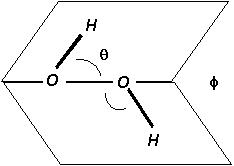
Figure 1. H2O2 molecular
Properties of H2O2 H2O2, hydrogen peroxide, is a stable, widely used and inexpensive chemical; all of its major properties are well known [H2O2.com web site]. The H2O2 molecule is shown in Fig. 1, where the steric angles shown are θ(H-O-O angle) = 95° ± 2°, and Φ(Dihedral angle) = 120° ± 3°. It is a liquid at room temperature, with density of 1.45 g/ml and a significant vapor pressure. H2O2 freezes at -9°C and boils at 160°C. Its room temperature vapor pressure is about 200 Pa, or 2 torr.
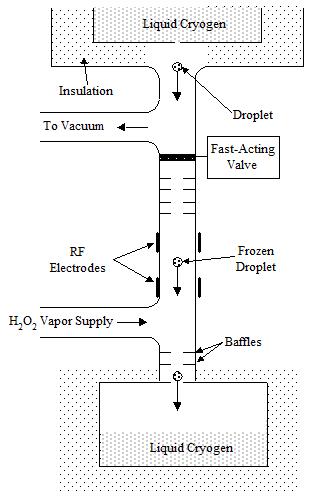
Figure 2. Schematic of apparatus to be used to generate, capture and stably store HO2.
Properties of HO2 Whereas the thermo-dynamical data on H2O2 is easy to find, the same can not be said for the kinetic data, especially concerning its reaction to form HO2. The ionization potential and relevant thermochemical energies of HO2 have been measured [20] and a variety of thermodynamic data are available from current databases (e.g. NIST). The NIST database also provides data on the ion reactions that lead to the formation of HO2. Of course, there is no data on the properties of bulk HO2. The HO2 radical is planar, and the extra electron tends to be associated with the O2 dimer.
H2O2/HO2 Reaction Kinetics. The kinetics of some of the primary reactions associated with H2O2 formation and destruction are known, but cannot be compiled here. For the recombination reaction 2HO2 => H2O2 + O2 the rate constant is log10k = 12.25 at room temperature [21].
HO2 Self Reaction Barrier The critical issue for HO2 metastability is the existence of significant potential energy barrier to self-reaction. Such a barrier has not previously been found, either theoretically or experimentally, due to the difficulty of both efforts. That it exists is strongly suggested both by the slow rate constant and the geometry of the molecule and its reaction intermediate, H-O-O-O-O-H.
Experiments. The goal of experimental design is twofold: to generate and store HO2 stably, and to separate HO2 from its H2O2 precursor so that it can be stored in high concentrations. The most important effort is to demonstrate the long-term stability of HO2. The basic technique is to generate the HO2 in a weak plasma discharge and expand the radical-laden gas to impinge on a cryocooled surface [22].
The apparatus is shown in Fig. 2. The reaction products would be cooled and captured by particles passing through the discharge. The reaction products can be easily accumulated and concentrated for engineering production.
The primary species collected will be H2O2, with a small fraction of HO2 present. Frozen N2 or Argon droplet will be used to quench and capture the H2O2/HO2 mixture. The condensed material will form as a snow that can then be collected (it may float or sink) that can then be collected and examined optically; its presence and concentration will be immediately identified by its IR signature.
Separation Design. Separation of the HO2 from the H2O2 is more difficult. One way to do the separation is to ionize the gas mixture using a low energy electron beam, then expansion- cool the HO2 radicals in the H2O2 carrier gas. Once the charged gas is expanded and cooled it enters an ion drift chamber. The drift chamber is configured with electrodes that create a divergent electric field that forces the charged HO2 particles to move relative to the H2O2 molecules as a result of their different ion mobilities. A cross-flow of cold helium would sweep the H2O2 molecules out of the drift chamber before they reached the liquid cryogen collection location. A film of concentrated HO2 molecules would condense on the liquid cryogen and could be collected by draining the liquid. The design of this apparatus is under development at Thoughtventions.
HO2 Value. The primary benefit of a HO2 CSM would probably be to catalyze an oxidation reaction. The other benefit would be in added heat release of the reaction. A fuel of H2O2 with a significant of HO2 fraction may be very valuable.
These routes to CSM production are described in general and for specific cases. The van der Waals compound H2Ne2 is described, together with its fabrication. The production and storage of HO2 is described. Specific techniques for separation and concentration of CSMs are described. The benefits and use of CSMs in combination with standard propellants are discussed.
DOPED CRYOSOLIDS
The characteristics of cryostabilized additives (CSMs) can be defined and potential candidates identified. A critical element for the fabrication of CSMs is the path between its created state and its cryostabilized state. Specific paths to the scientific and engineering production described below include 1) the formation of room temperature van der Waals compounds, 2) production of cryostabilized radical species, and 3) techniques to concentrate or separate CSMs. This document focuses on experimental rather than theoretical or computational approaches. Analytical experimental techniques for determining material properties, while critical, will not be discussed.
The most obvious host materials for CSM propellants are O2 and H2, but any propellant material can be cooled to cryogenic temperatures - typically below 100 K - to provide stabilization. Typical CSM densities for energetic fuel enhancement are on the order of 10 mole % [23]; a catalytic CSM may be useful in significantly lower concentrations. It is interesting to note that an example is an O2/H2 mixture - stable at 10 K. Isp improvements for various species are given in Table 1.
CSM Stability A stable material at a specified temperature is defined as a material that will not spontaneously change state in response to its thermal environment. A metastable material is one that does not change state over some reasonably long period, but does eventually change state. For CSMs, a Commercially Applicable metastable material is defined as a material with 99% of its original CSM concentration over a period of 3 x 10⁶ s (1 month); a usable propellant material. Metastable materials that are stable to at least 50% concentration over 3 x 10⁴ s (10 hrs) are useful for Laboratory Applications. Metastable materials stable over 3 x 10² s provide easy laboratory diagnosis.
Table 1. Theoretical specific impulses of metal atom doped solid hydrogen propellants. (assuming Pchamber = 1000 psia, Pexhaust = 1 atm., shifting equilibrium) [23].
| Additive | Isp | 5% molar concentration Improvement over LOX/LH2 |
| None | 389 | --- |
| H | 407 | +5% |
| Li | 401 | +3% |
| Be | 451 | +6% |
| B | 470 | +21% |
| C | 469 | +21% |
| N | 414 | +6% |
| O | 411 | +6% |
| F | 398 | +2% |
| Na | 373 | -4% |
| Mg | 398 | +2% |
| Al | 425 | +9% |
| Si | 432 | +11% |
| Ti | 404 | +4% |
A common misconception is that CSMs cannot exist in useful concentrations because the probability of two reactive atoms being adjacent approaches unity as the reactive atom fraction in the host material approaches 10% [23]. When diffusion processes, particularly diffusion along grain boundaries, are taken into account, the estimated limiting concentration falls to 1-2%; work in radical trapping within solid matrices imply limiting concentrations of less than 1%.
This only applies for species that have a zero potential barrier to reaction along the spatial coordinate between the molecules. There are a number of species (including radicals) of interest that have non-zero but small potential energy barriers to reaction. There are a smaller set of CSMs with potential barriers only in specific directions; these might be stabilized in an external electromagnetic field or as a van der Waals compound.
Detailed investigation of complex reaction potential energy surfaces is a modern science, although binary potential work is extensive (e.g. the H2 potential [24]). Compilations exist for a variety of element pairs in their ground state (e.g. [25] for alkali-inert pairs). The difficult problem in solid state compounds is to define and model the many-body and long range effects. Here, self reaction barriers are of importance. These barriers, as others, arise from both molecular geometry effects, reaction intermediates, electron configuration effects, and others.
One can define approximately the needed potential energy barrier height. Energy stability in the solid phase is quite different from that in the gas phase because there is no high-energy tail of the vibration distribution to initiate reactions. The energy cutoff is kΘD, where k is the Boltzmann constant (10-16 erg/K) and ΘD is the Debye temperature of the solid. For Ne this energy is 6 x 10-15 ergs or 0.004 eV, so species with this reaction barrier height will presumably be stable in this host. This is about a factor of 1000 below the normal chemical heat release/enthalpy difference between common reacting species; relatively small reaction barriers become important.
CSM Formation Given the generic reactivity /instability of the species that are potential CSMs stability issues are secondary to formation issues. Theoretically stable CSMs may have no path to their formation, since they cannot be formed in situ in the cold solid matrix. Aside from the problem of reaction due to natural concentration fluctuations, there is the problem that during the process of high concentration deposition the addition of the reactive species to the solid leads to reaction as a result of the energetic interaction between molecules being added and those in the solid. This can occur both in the gas phase and in the accretion layer on the surface of the solid.
Candidate CSM Materials. There are a wide variety of materials that can be chosen for deposition into a solid matrix. These materials fall into number of different classes according to the type of van der Waals solid crystal structure that is formed by the mixture. The important characteristics of the CSM species are its size/radius relative to the size of a matrix molecule, its outer electronic structure, and whether the activation energy for self reaction is zero, or significantly greater than zero. The CSM can form an interstitial impurity as small atoms in a large atom/molecule matrix, it can form a substitutional impurity for CSM and matrix species of comparable size, or it can be an impurity that displaces a significant number of matrix molecules in the lattice. Attention is usually focused on the light atom group Li, B, Be, and C because these isolated atoms provide a very high heat release upon combustion; light atoms are energetically favored for propulsion. Most, if not all, of these species have zero reaction barrier energy.
The Host Matrix This discussion will concentrate on H2 and to a lesser extent O2 and the case where a matrix is necessary for the formation of the CSM. The discussion here is necessarily condensed.
Solid H2 [24] has been chosen as the primary initial host matrix because: 1) it is the most well known of the cryogenic solids with a simple, spherically symmetric molecule, with a single, simple phase, 2) it has been and can be theoretically described to a much greater degree than other cryogenic solids, 3) knowledge gained of its properties is likely to have fundamental importance for physical chemistry, 4) it is a common, simple, standard propellant.
ParaH2 is a quantum solid with significant zero-point energy where anharmonic effects in the lattice dynamics have increased beyond the treatment of perturbation theory. Although H2 and Ne have similar σ and ε parameters, an H2 molecule is significantly larger than a Ne atom.
The engineering properties of solid cryogenic H2 has been compiled [26] in contrast to standard thermodynamic properties [27]. From this point on the term solid H2 is assumed to refer to pure para-H2. Experimentally, standard catalysts convert normal H2 to para-H2.
Diffusion processes in the lattice control whether a CSM atom/molecule will move to and react with another CSM atom/molecule. In all cases, since the impurity is much more massive that the H2 molecules in the lattice, its fundamental diffusion rate is much lower. However the much more mobile H2 molecules can move around it and provide an additional driving force for its motion through the lattice.
Solid H2 Surfaces Experiments involved with deposition on solid H2 surfaces consider that at temperatures above 3 K, there is a high mobility H2 layer on surface of the solid [28]. This means that true gas-to-solid deposition on H2 can only take place at temperatures below 3 K. At higher temperatures there is a build-up of a smooth, homogeneous film up to a limiting thickness d1 of 3 to 4 monolayers, beyond which the condensing molecules aggregate to form bulk crystallites (Stranski-Krastanov growth). H2 mixtures will thus normally produce pure crystallites of the depositing species at temperatures over about 3 K. Since the wetting behavior is determined by a delicate competition between adsorbate - adsorbate and adsorbate - substrate forces, it is probable that some substrates will exhibit complete wetting even below the triple point temperature, including perhaps more complex, multilayer systems.
Solid Behavior The diffusion rate of species within a cryogenic matrix or compound is not well known in general. Assuming the basic classical diffusion law D = D0exp(-ED/kBT), for self- diffusion, D0 values are estimated to be 3 x 10⁻³ for H2 and 4 x 10⁻⁴ for D, with activation energies ED/kB of about 200 K [29] at zero pressure. This would imply D(4 K) = 6 x 10-25 cm2/s. At low temperatures quantum diffusion (tunneling) leads to much high actual diffusion rates; D(H2) = 2 x 10⁻⁶e-112/T, so that D(H2,4 K) = 1.4 x 10⁻¹⁸ cm2/s. The absolute numbers are very small; quantum diffusion is difficult to measure experimentally. For planar diffusion from 100% concentration into a semi-infinite body at 4 K, the concentration would reach 50% 1 nm away in 2 hours. Diffusion proper is quite different from short-range relaxation, which is also called reclusterization or configurational relaxation. Microscopic concentration differences smooth out in a macroscopically homogeneous mixture.
The case of more interest is that of a larger species than H2 moving toward another of its kind as a result of attractive forces between these two atoms. In this case the heavier and larger molecules must essentially plow through a mass of H2 molecules, and the diffusion rate would be expected to be much slower than the movement of light and small H2 molecules. Diffusion in practical materials is strongly dependent on lattice imperfections - vacancies and a variety of structural imperfections. Impurities in solid H2 are thought to have important effects on the nearest neighbor sphere of surrounding H2s. The displacement of nearest neighbor shells would be expected to have major effects on solids with high impurity concentrations, but these effects would be very different in a regular crystal compound.
Vacancies in solid H2 are equilibrium lattice defects and their concentration is unambiguously determined by temperature and pressure. At the triple point (T = 13.81 K) of H2 the concentration of vacancies is from 0.1 - 0.01 %, decreasing rapidly with decreasing temperature. Dislocations and packing defects are the main defects in single crystals and polycrystalline samples (with respectively large grains) of pure H2. The density of dislocations can be decreased from 1010 cm-2 to values as low as 102 - 103 cm-2 in well annealed samples [30]. One would thus expect diffusion in solid H2 to be strongly dependent on the history and preparation of the sample.
The O2 Host Solid O2 exhibits a number of unusual solid behaviors associated with the molecule's magnetic field. There are major solid phase changes versus temperature with associated changes in diffusion and major changes in specific volume. The strength # and thus solid binding forces increase with decreasing temperature with significant asymmetries in the crystal lattice. This implies that there will be significant energy and reactivity differences with the lattice position of the CSM.
It seems probable that the most practical paths to achieving a relatively high concentration of CSM are through concentration after low concentration trapping, and the formation of van der Waals compounds through epitaxial deposition processes.
ATMOSPHERIC VAN DER WAALS COMPOUNDS
The creation of vdW compounds allows the formation of a stable crystal with high relative concentrations of separated species, and it allows the formation of this crystal at low temperature with low kinetic /thermal energy species. The existence of vdW compounds has been conclusively demonstrated at high pressures [31], and various stability arguments and experimental data imply that these or related compounds can be created at pressures on the order of 1 atm or less, at least in a long-term metastable form.
van der Waals Crystal Compounds A significant number of binary vdW compounds have been found to exist experimentally at high pressure. The list includes Ne(He)2, A(H2)2, CH4(H2)x, N2-CH4 system, and He(N2)11. Their crystal structure can also be plausibly predicted based on free energy calculations and by hard shell packing models [32].
Van der Waals Epitaxy. Van der Waals epitaxy has been investigated [33], but work has since lapsed. Epitaxial crystals can be deposited with large lattice mismatches compared with the few per cent typical of standard epitaxial growth. Critical to this process is the creation of substrates without dangling bonds. Such surfaces are usually created using planar materials that can easily be cleaved, or ionic materials. There seems to have been almost no previous work done on epitaxial growth of cryogenic crystals.
Crystal Packing The intermolecular interactions of vdW compounds, mixtures, and impurities with vdW solids are by definition small compared with those of common materials; the approximate binding energy [34] of an H2-H2 cryogenic dimer is 2.9 cm-1 compared with the binding energy of H2 itself - 104 kcal/mole, or 36,400 cm-1. Since interactions between vdW molecules during solidification remain unchanged except for small perturbations, these interactions can be treated for some purposes as interactions between spheres whose size is determined by some consistent measure of the size of the molecule/atom. In assigning a size, quantum species have a size larger than that implied by their potential energy as a result of the effect of the zero-energy vibrations of the molecules.
The fact that high-pressure vdW compounds are often of the AB2 stoichiometry with a Laves phase crystal structure is often explained as a natural consequence of the packing stability of a binary mixture with a certain relative species size (close to 1.2), using as a reference metal lattice formation [32]. In general, sphere packing has been shown to generate both simple and highly complex structures. Some (AB13) are formed purely as a result of entropy-driven formation, rather than by free energy minimization. The most commonly found AB2 structure is made up of alternating hexagonal layers of the small and large particles. The large spheres (A) form close packed layers aligning directly above each other along the c axis while the small spheres (B) occupy trigonal prismatic sites between these layers and form planar hexagonal rings. This structure would be appropriate for epitaxial growth. It should be noted that this structure is not the structure of high pressure vdW compounds found experimentally. X-ray results [35] show these to be a closely related Laves phase structure. General packing investigations [36] imply that the diameter ratios (dA/dB) need to be in the range 0.5 - 0.8, with possible islands of stability at higher dA/dB. Larger dA/dB leads to a random alloy with fcc structure. Packing arguments provide a partial guide to the effects of adding impurities to a vdW solid.
Once H2 has been chosen as the host matrix, the choice of a compounding species is critical, and should be one that leads to a combination of the highest chance of experimental success with the most general application. Ideally the chosen species would be highly reactive, capable of 1) stabilization and 2) implantation, and easily diagnosable. To date no highly reactive species been found that can be combined with H2 in high concentrations. The experimental complications of using a reactive species are formidable. Reactive species have very complex vdW interactions, both short range and long range, probably only a few specific compounds are viable. A first effort has been dedicated to creating a low pressure vdW compound based on species related to those formed at high pressure.
Given the goal of creating a H2X vdW compound, where X is an inert species, one must assess which species is most likely to lead to successful compound formation. X must behave as a vdW species, which means that it must have self-reaction and H2 reaction activation energies that are greater than the thermal and quantum mechanical activation energies it encounters. Some atomic species are thus excluded. For example C reacts with H without a barrier, whereas B forms a vdW complex with H2 because significant energy is required [37] to form H-B-H, the stable product of B and H2. Finding which species have Eact > 0 is difficult because the relevant reaction energy surfaces are often 3-D, reaction intermediates are not well known, and reactions in general have not been studied at low temperatures. The noble gases such as Ne, Ar, and Xe, as well as the common cryogenic gases N2, CO2, CO, and CH4 are more obvious candidates for initial experiments. These materials form vdW compounds naturally only at high pressures, indicating that crystallization from a liquid mixture will not lead to low pressure equilibrium compounds.
The concept that will be investigated in this work is to use vapor phase deposition to form the crystal. In this case (meta)stable crystals could be formed either through epitaxial growth on a substrate, or as a result of configurational relaxation from a more amorphous, but compositionally identical solid mixture. To perform epitaxial growth of a crystal with weak bonds or a locally uniform amorphous mixture using vapor phase deposition, the vapor molecules should be deposited at as low a temperature with as narrow a thermal dispersion as possible. This also minimizes the temperature rise of the solidifying substrate, since the heat release is smaller during condensation. Minimizing heat release is very important for the deposition cryogenic solids, as a result of their poor solid thermal conductivity. The gas (aside from He and H2) with the lowest condensation temperature and lowest heat of solidification (by far) is Ne.
Neon has a number of other advantages for this purpose. Its molecular volume is small enough relative to H2 that it falls in the proper range of relative species sizes to form a Laves phase crystal [38] of the form H2(Ne)2 similar to the vdW compounds formed at high pressure. Ne can also be considered an isotopic impurity in H2 with very similar Leonard Jones potential parameters; the species size difference occurs mostly as a result of the large zero point energy of H2. H2 is a quantum solid, whereas quantum effects in Ne are much smaller. Ne has the added advantage (for this approach) that it is not soluble with H2 to a significant degree either as a liquid or as a solid [39]. For this reason partial solid mixtures that might obscure the detection of the vdW compound are very unlikely to occur, as opposed to the alternate possibilities. Furthermore, H2/Ne mixtures have been extensively studied and characterized.
Crystal Structure and Stability. The existence of high pressure vdW compounds implies the stability of a related H2(Ne)2 compound. Such Laves phase compounds form when the size ratios of the component species are near 1.20 [31,35]. The hcp lattice spacing of H2 is ao = 3.76 A, which is also the effective molecular diameter in a hcp lattice, whereas the spacing of Ne at 16 K is ao = 4.88 A [38]. Like related rare gas solids, Ne is a solid with the fcc structure, so that its effective atomic diameter is 4.88/√2 = 3.17, and the H2/Ne effective diameter ratio is about 1.19. The σ parameters for H2 and Ne potentials are 2.96 and 2.79 [29] respectively to give a ratio of 1.06; the reduced molar volume [40] of H2 relative to Ne resulting from quantum effects implies a further size factor of 1.09 to give a ratio of 1.16, which is consistent with the relative lattice parameters. Since the proposed H2Ne2 structure arises from alternating layers of larger (H2) and smaller (Ne) species, there should be a number of ways to create this (meta)stable lattice using gas phase deposition. The compound cannot be formed from the liquids because they are not miscible at low pressure, or by deposition onto the H2 solid above 3 K as a result of the liquid layer on its surface. H2/Ne is designated by its probable stoichiometry: H2Ne2.
The general reason that H2Ne2 has not been created previously is that there is no simple or natural dynamic route to its formation. Ne is not soluble in H2 to any significant extent, preventing the solid solution route. Most previous experimental work has also been done at temperatures higher than 3 K, so the mobile surface layer prevents the formation of H2Ne2 via condensation from the gas. There is also a narrow concentration range for stable formation of the H2Ne2 crystal such that the small concentrations of a H2Ne2 crystal that may have been created are very difficult to detect.
Material Properties. The basic description of the postulated H2Ne2 crystal is that of a fcc or hcp crystal with alternating layers of light and heavy species. The complexity of the crystal description in terms of its detailed properties arises from the quantum mechanical behavior of the H2 molecules. Ne is a closed shell atom, with negligible dipole or higher order moments. H2 molecules, even with their inherent nuclear asymmetry, have a nearly spherical potential surface. H2 also has significant electronegativity. The material is expected to be highly sensitive to impurities; the effect of Ne isotopes is unclear. Macroscopic properties of the crystal such as specific heat and thermal conductivity can be measured, and microscopic properties such as optical properties can be measured using only a thin layer of the crystal or micro crystals spread throughout a solid. As a result of the delocalized nature of the electron structure of H2, a H2Ne2 crystal will have some very unusual electronic and optical properties.
A generic experimental problem that must be overcome is the deposition of species at low temperature. In the past implanted species had high energy (furnace vapors, laser ablation, nozzle expansion).
The approach will center on van der Waals epitaxial growth using vapor deposition, based on experiments using an existing Janis Supertran VP cryostat. This is a standard liquid He cryostat that controls sample temperature down to liquid He temperatures. Temperatures below 4 K can be achieved in this cryostat by pumping on the liquid He in its reservoir. Opposed optical access to the sample is provided from two orthogonal directions.
Apparatus A schematic of the crystal growth cell to be used for this work is shown in Fig. 3. It consists of an axial tube supplying H2, Ne, or mixtures with a tip directed toward a substrate, a thermally insulating deposition cell with a rotatable attachment fixture to the cryostat sample holder, windows (sapphire or beryllium) in the cell, temperature sensors, and a substrate if necessary for the epitaxial growth process. Sapphire windows provide optical access to the film; Be windows will be used for x-ray studies.
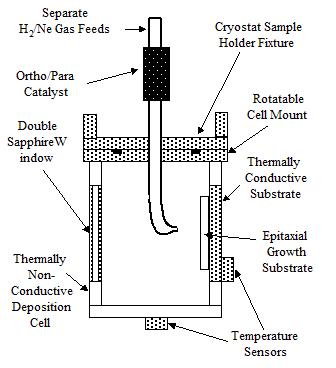
Figure 3. van der Waals condensation apparatus.
Gas Phase Deposition There seem to be three basic possibilities for forming a H2Ne2 crystal: alternating deposition of monolayers of H2 and Ne, epitaxial growth of H2Ne2 on a substrate that facilitates its growth, or deposition of a 1/2 stoichiometric gas mixture of a H2 and Ne onto the solid followed by high temperature annealing or plastic deformation plus annealing. In all cases the deposition must take place below 3 K to avoid separation of the pure substances in on the solid H2 surface. The goal is to achieve a solid structure that forms as H2Ne2 or a closely related structure that relaxes H2Ne2.
The most common route to add atoms to solid H2 has been to implant them from thermal sources, and rely on the low diffusivity in H2 to create a stable matrix. This works well for low concentrations and can be used for studying the properties of these isolated atoms [41]. At concentrations approaching 1% implantation fails because the high thermal energy tracks of the implanted atoms intersect with atoms already implanted and reactions result from the energy of the newly implanted atom, a fundamental limitation of all related techniques.
The achievement of a stable crystal structure will be achieved by relaxation of a slightly more energetic, slightly amorphous solid structure into a regular crystal compound. The experimental task will be to find a viable route for this process. There are a number of crystal structures that could be formed; three closely related Laves phases are possible [36]. The lowest energy structure of these [38] has alternating layers of small and large species, where the small species forms in hexagonal rings without the center atom that would make the layer close packed. This is the structure that lends itself to the alternating species monolayer approach. The structure that forms from the liquid mixture at high pressure in the Argon/H2 system is yet another, more complex and slightly higher energy structure. It is not clear and not explained why this structure forms in preference to the lower energy alternating layer structure.
The proper condensation rate will depend on the thermal conductivity, k, of the deposited material. For solid para-H2, k is near its maximum of 1.5 W/cm-K at 3K, and decreases with Ne content [29]. Assuming a sublimation heat release of 89 K/molecule and k = 1.5 W/cm-K, a 1 mm thick layer maintaining 3 K at its surface and 2.5 K at its rear cooled surface could support a deposition rate of 0.3 moles/cm2-s and a film growth rate of 7 cm/s; the actual deposition rate will be much lower. Related experiments [42] report that a deposition rate of about 10-5 mol/cm2-min of oxygen leads to snow formation.
The dewetting phenomenon prohibits the use of temperature induced reorganization of thin films. Growth conditions must cause the species to rearrange or arrange in an ordered lattice, rather than randomly stick to the surface. This may be done by depositing a layer of H2 that preferentially locates at half of the H2Ne lattice sites, then adding Ne to fill up the other lattice sites to complete a full layer of the H2Ne crystal. The initial layer would presumably be guided by the properties of the substrate. Plastic deformation can perturb the crystal structure for improved stability.
The successful formation of a H2Ne2 crystal using van der Waals epitaxy may depend on finding a suitable deposition substrate. Silicon and sapphire are inappropriate due to their small atomic spacing. A pure single-crystal of H2 is another material that will be tried, certainly for the alternating H2/Ne monolayer approach, since the spacing between H2 and Ne sites is expected to be on the order of 3.5 A. Covalently bound substances have too small an interatomic distance. Ionically bound materials appear to be the best candidates. LiI has a 3.5 A spacing for a bcc lattice. CsF would be another, similar candidate. Since H2 has a negative electron affinity and is larger than Ne, then CsF would probably be a better choice, where the larger H2 would be attracted to the positive Cs ion.
CONCENTRATION OF CRYOSTABILIZED MATERIALS
Although there are many possible techniques for concentrating cryostabilized materials (CSMs), the techniques that appear most promising without extensive preliminary experimental research are dictated by the nature and current practice of cryogenic fluids. The key to creating a pure CSM is to trap each individual molecule/atom and cool it in isolation before concentration by a variety of means. The coldest, totally non-reactive material that can be used to cool a CSM is lHe. It maintains its temperature of about 4 K in spite of heat input (from condensing CSMs) because it is a boiling liquid - evaporative cooling balances deposition heating. Liquid He also provides another important advantage for pure CSMs: it can be used to easily transport the isolated CSM species to a location away from the trapping zone, where the CSM can be concentrated at a uniformly low temperature.
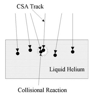
Figure 4. Schematic of CSM accretion layer.
A fundamental problem in the trapping and cooling of a CSM is the possibility of reaction in the accretion layer where the CSM particles are slowed and cooled. Fig. 4 shows the process schematically. The CSM particles have directed momentum that causes them to penetrate the surface of the liquid (or solid) in a path determined by the direction of entry and the slowing forces of the liquid. Although the CSM does not react with the cooling liquid, it will react with any other CSM particle that it comes in contact with as it passes through the liquid. Due to a natural dispersion in direction and momentum, particle tracks will overlap as the density of CSMs in the liquid increases. Thus the density of CSM particles must be kept low enough to minimize the probability of reaction. This can be done using either a batch or a flow method. In a batch method when a predetermined concentration is reached, the deposition is turned off until the matrix can be refreshed by physical displacement. The deposition surface is continually refreshed in the flow method.
The more efficient technique is to present a continuously refreshed liquid surface to the incoming CSM particles to limit the buildup of CSM atoms at the surface. The required speeds of the flow of a liquid bath to achieve this imply that the CSM beam must be narrow and deposition rates restricted. This limitation is avoided by using co-flowing CSM beams and helium sprays. Much higher helium flow velocities can be achieved in this way, and the reduced volume density of the spray allows penetration of the CSM beam into the spray core. Furthermore, the droplets in the spray will be rotating and have internal motion, continually presenting fresh surface to the CSM beam.
A conceptual schematic of a pure CSM concentration machine is shown in Fig. 5. The principal is to collect cooled and trapped CSM material in lHe then crystallize the CSM, removing the lHe for recycling. Helium vapor generated by the CSM cooling is also collected, reliquefied, and reused. The only inputs to the device are CSM material and power. The entire apparatus is insulated and in vacuum. A thermal or beam source provides the isolated CSM species. The geometrical configuration of the CSM trapping in lHe is dictated by the reaction concentration limits discussed above. The solid, cold CSM would be shed from the substrate for use. Smaller particles could be generated by continuous shedding of a thin film as it builds up.
Figure 5. Concentration machine for creating a pure, cryogenically stabilized additive (CSM).
An estimate of the scale of a potential CSM production plant is as follows. A typical current launch to Low Earth Orbit (LEO) uses on the order of 50,000 kg of propellant. Assuming a 5 mass % CSM implies that 2500 kg of CSM must be produced for the launch. Production capacity support of one launch per week (6 x 10⁵ s) implies a CSM production rate of about 4 g/s. The critical factor then becomes the flow rate of lHe that is required to supply this CSM mass flow rate. A 1000/1 volume ratio implies a lHe flow rate of 4 kg/s, but this implies 1 CSM atom in a cube of lHe that has 10 atom on each side. This is a high enough concentration to imply a significant collision reaction rate. A 100 atom cube would be a lower limit, implying a 4000 kg/s. A reasonable compromise would be 400 kg/s. A droplet field with a 0.5 m x 1 m cross section and a mass flow rate of 10 kg/s is readily achievable, implying a 40 m long facility to produce the CSM mass generation rate required. For an average droplet size of 0.1 mm, and an average speed of 20 m/s, this would imply a volume flow rate of 20 m3/s, at a volume loading of 0.1%. These are numbers that can be achieved with standard technology, but the actual case should require a somewhat smaller facility.
The deposition profile is also credible. For a 0.1% volume loading, there are about 2000 drops/cm3, so that approximately 1.6% of the frontal area of a cubic cm is blocked by droplets. An approximately 100% blockage (on the average) would then occur at a depth of about 60 cm, which is the depth of the droplet field.
This is also a reasonable CSM generation rate. For a 40 m long facility generating a total of 4 g/s of CSMs, 0.4 g/s per m length must be generated. Typical growth rates for vapor deposition are on the order of 100 nm/s, which, for a 1 m x 1 m area implies 0.1 cm3/s, or 0.4 g/s for a double sided deposition system as shown in Fig. 5, and assuming only a CSM specific gravity of 2.
It seems thus that a pure CSM generation facility is a feasible project, once an appropriate pure CSM is found.
Concentration Diagnostics. There are four basic techniques that are used to probe cryosolid matrix/CSM crystals: spectroscopy, electron diffraction, x-ray diffraction, and calorimetry. Electron diffraction is appropriate when the equipment is available and the X-ray response of the CSM differs significantly from any host that is also present; H2 has a small scattering power. XAFS can be used to examine nearest neighbor characteristics and is more widely available. Matrix isolation spectroscopy studies of impurities in H2 and other matrices has a long and detailed history [43].
Concentration Techniques
CSMs are assumed to be formed in the gas or plasma phase. The final product of the concentration technique for an unstable CSM is a CSM-doped solid propellant with a CSM concentration of at least 1 mole-%. All of the combinations of state changes can be considered for concentration. Concentration can be done in or from the gas, liquid or solid phase, followed by formation or condensation into the necessary final solid state. It should also be stated that the final CSM/inert solid may either be a mixture or a true compound.
Concentration Fluctuations
The fundamental difficulty of concentrating unstable CSM's is the avoidance of self-reaction, and elimination of the enhancement capabilities of the CSM by this self-reaction. Self-reaction can also have a more serious effect: it can destabilize the entire matrix, leading to potentially catastrophic results. The transition from isolated reaction to general instability is dependent on the details of the solid and will not be considered here, where the goal is to avoid significant reaction.
One fundamental problem associated with the avoidance of self-reaction, and the consequent necessity for avoiding spatial proximity of CSM species, is the natural fluctuations of the CSM. In the gas and liquid these fluctuations exist in both position and velocity space, whereas in the solid the fluctuations are dominated by variations in the CSM atom position relative to a totally uniform distribution within the inert matrix. In previous work CSM-doped inert matrix concentrations have been limited by a number of effects, including energetic reactions in the accretion layer, CSM diffusion, and local concentration fluctuations. All of these factors can be reduced to a certain extent, and all are important for CSM concentration and limitations in CSM concentration.
As a preface to considering CSM concentration, techniques to avoid limits imposed by energetic reactions in the accretion layer and CSM diffusion must be briefly addressed. It is critical to avoid the formation of any kind of high mobility layer associated with the accretion process. In the case of para-hydrogen (para-H2), due to the quantum nature of the solid there is a thin, highly mobile layer on the surface of all para-H2 crystals at temperatures greater than about 3 K [44]. Thus, all accretion should be performed at lower temperatures, although experimentally this has not been done in the past. To minimize CSM diffusion, low temperatures and high crystal perfection (single crystals with few defects) are the key elements. Some elements (such as O2) have an inherent difficulty in forming high quality single crystals, due to the constraints of the necessary phase changes associated with cooling the sample to liquid helium temperature.
The issue of fluctuations in local CSM concentration must be addressed in the formation stage, and there are techniques available to do this. By reducing CSM atom/molecule position fluctuations, higher levels of CSM concentration can be achieved.
Gas Phase Concentration
In the gas phase, atoms/molecules have positional and velocity fluctuations arising from the standard Maxwellian velocity distribution associated with an equilibrium temperature. This velocity distribution and the associated position distribution can be modified by constraining the atoms with body forces (electrical or magnetic) or through the use of external boundary conditions such as physical walls. Some experimental techniques of direct use to allow increased concentration by reducing gas phase fluctuations can be discussed.
One technique for concentration in the gas phase is by charging the CSM, the inert carrier gas, or both, and then manipulating the charged species using electromagnetic fields. One species can be separately charged by taking advantage of the different ionization potentials of the different species; excitation by electron beam or optically below a specific energy level will lead to the ionization of the species with the lower ionization potential. Optical ionization of either species irrespective of ionization potential can often be done using multiple photon excitation of appropriate energy levels. A more complex technique, however, usually implies a higher cost.
The charged species can then be moved in relation to the uncharged species. In the case of a collisionless mixture at low pressure, if the inert matrix gas is uncharged, it can be removed from the charged CSM simply by electromagnetically turning the flowing CSM, allowing the inert gas to separate by inertia. The concentration of the inert gas surrounding the charged CSM can be reduced by allowing it to expand normally while the CSM is constrained by the electromagnetic fields. The concentrated CSM/inert gas mixture would then be collected in a more standard fashion by co-condensation. This is more a technique for increasing area deposition rates rather than absolute concentration, since gas phase concentration limit result from high interdiffusion rates.
At higher pressures, similar effects are achieved in what are termed "drift tubes," where the charged species does not undergo significant charge exchange and is moved on average relative to the carrier gas in spite of numerous collisions with the carrier gas (not other CSM atoms). Thus, in a similar manner to the collisionless case, the inert carrier gas can be expanded and its relative concentration reduced while the CSM is constrained by the electromagnetic fields. Co- condensation again completes the process.
Solid boundary walls can be used to aid concentration in a number of ways. The cold walls of a tube can be used to trap CSMs that have any transverse velocity, reducing velocity fluctuations in two of the three dimensions that determine the movement of the CSM molecules. For the case of CSM's co-flowing with an inert gas that forms its stabilization matrix, if the transverse velocity is reduced enough the lateral concentration fluctuations of the CSM are reduced, so that it can be condensed in higher concentrations.
A special use of walls is the expansion of a gas through a nozzle. This process changes the thermal energy of the gas into directed kinetic energy at greatly reduced temperature. This is a common technique used to "freeze" the properties of a gas. Direct deposition using this technique leads to large concentration fluctuations due to collision-induced concentration fluctuations. However, if this atomic beam were charged and slowed in a electromagnetic field, concentration fluctuations would be greatly reduced and the concentrated co-deposition could take place. In this case, the elimination of particle tracks in the surface layer allows higher concentrations to be laid down. Charged particle slowing is common to many techniques that extract energy from a charged gas. Overall deposition rates would be lower due to limits on densities in a charged-particle beam.
The importance of low temperature deposition is indicated by data that shows that whereas thermal sources depositing into solids have multiple substitutional sites within the solid lattice, laser ablated material deposits in a single site, due to the narrower range of energies associated with laser ablation [45]. The fewer the number of types of substitutional sites, the more regular the crystal, the less the diffusion in the crystal, and the more controllable is the entire process.
Liquid Phase Concentration
Concentration techniques that only involve the liquid are limited by the relatively high diffusion rates of the CSMs in the liquids. However, an inert cryogenic liquid is an excellent tool for rapidly cooling CSMs impinging on its surface. Internal flows redistribute the CSMs within the liquid, allowing greater deposition per unit area, but overall concentration limits per unit volume are much lower than those for solids.
Cold CSMs in an inert liquid, in spite of their low concentration, could be deposited and concentrated in a manner analogous to crystal growth from solution. The process would begin by trapping both the CSM and the inert matrix molecules in a liquid that is a third, different material. Trapping in the liquid state of the inert matrix by itself would not allow controlled crystal growth of that matrix at temperatures well below the melting point of the solid, since solidification would be rapid and uncontrolled. This implies that both the CSM and the inert matrix molecules must be soluble in the third, carrier liquid. The carrier liquid must, of course, remain a liquid at the crystallization temperature of the inert matrix. The key to this technique is the fact that the CSM atoms/molecules will join themselves to the solid preferentially at certain sites, rather than randomly on the surface. This will tend to create the high quality crystals that are necessary to prevent CSM diffusion and reaction at higher concentration. The overall concentration of the CSM relative to the inert solid matrix would be determined by their relative concentrations in the liquid. The primary problem with this process for engineering purposes is the slow rate of deposition. It certainly appears to be an excellent vehicle for creating high concentration CSMs, and may also eventually prove to be a practical commercial process.
Experimentally, there are not many liquid carrier/inert matrix combinations to choose from. Liquid He/solid H2 is probably not appropriate, since H2 is not soluble in LHe and floats on its surface [46]. There may also be a problem with the solid solubilities of the different candidate materials. As solids, Ne and H2 are not soluble; during attempted solidification, Ne crystals form on surface [47]. In liquid form, however, there are broad temperature and concentration ranges where H2 and Ne have complete solubility [48]. No other liquids appropriate to sH2 growth at 10 K exist.
The other major inert solid matrix of propellant interest is O2. The difficulty with solid O2 is that there is a major volume change associated with the phase change from the rhombohedral β- phase that exists in the temperature range from 43.8 K to 23.9 K (sp. gr. = 1.50), to the monoclinic α-phase that exists at temperatures below 23.9 K (sp. gr. = 1.55) [8]. This volume change leads to crystal defects that cannot be annealed out if an O2 crystal is cooled from melt temperatures to below 24 K. Two liquid carrier/sO2 combinations are thus available: lNe as a carrier liquid at 27 K crystallizing β-phase solid O2, and lH2 as the carrier liquid at 20 K, crystallizing α-phase solid O2 as the inert matrix. The lower temperature process using lH2 would be preferable in terms of diffusion in the solid, but as a practical experiment, the inertness of lNe is much preferable as a liquid to use for trapping the possibly hot CSM atom/molecules. This appears to be a very promising technique.
An intriguing addition to the crystallization technique is the use of optical excitation to dissociate reaction products generated from CSM contact back into the original CSM form. The surrounding cold liquid would absorb the energy from this dissociation reaction. This process has long been used to create atomic species in solids for matrix isolation studies (e.g. [49]). This technique might allow high concentrations of the CSM to be formed in the liquid and thus the deposited solid.
Solid Phase Concentration.
All of the solid phase techniques considered here are surface processes; it is believed that bulk solid processes are too intractable to be commercially useful. Although sublimation concentration, the initial concept developed by the author for solid phase concentration, is a surface process, it assumes that the structure of the surface of the solid is similar to that of the bulk, which is not usually the case. Other concentration techniques that use surface properties will be discussed below.
Sublimation Concentration. Sublimation concentration refers to the process by which a condensed van der Waals gas that provides a matrix for the CSM can be sublimed to concentrate the CSM at the surface. The surface-concentrated CSM is then harvested in some way or buried by unconcentrated material and the process is repeated.
Sublimation Concentration Machine. Figure 6 shows a schematic of a sublimation concentration machine designed by the author. It uses three stations to perform the basic sublimation concentration functions.
At station #1 the CSM and inert gas are co-deposited at low concentration - but at the highest stable concentration that the deposition process can tolerate. Deposition takes place on a cooled substrate that stabilizes the mixture, and it takes place on top of a thin layer of pure inert matrix.
At station #2 sublimation of the inert part of the matrix occurs, concentrating the remaining CSM at the surface. The sublimation process is an evacuation process that can be heat-driven externally as shown in the figure, or using heat conducted through the substrate. The volume around the surface of the deposited mixture is evacuated to drive the sublimation. Heating is performed to maintain the sample temperature and pressure, replacing the heat lost to the subliming inert matrix material. External heating is preferred over substrate heating to avoid thermal gradients in the sample. Optical heating can be done by broadband excitation in the UV or IR (most inert matrix materials are transparent in the visible), or by wavelength-specific absorption. Excitation of the CSM must be avoided to avoid any excitation of the molecule that may result in such effects as enhanced diffusion. Sublimation can be initiated or stopped at any time by controlling the heating. The substrate is then returned to station #1 for addition of another layer to be concentrated.
At station #3 the multilayered, concentrated CSM material is collected for formation into its final shape, either as particles in a pumped slurry, or as large segments for use in a hybrid rocket. Figure 3 shows a sloughing technique being used, where a very thin layer is loosened from the substrate by slightly warming the substrate. This assumes that many concentrated surface layers have been built up, so that the thin pure layer at the base is a small fraction of the overall volume collected.
Sublimation Concentration Feasibility Calculations. To demonstrate the practicality of sublimation concentration, a worst-case scenario of CSM sublimation concentration was examined; the case of a solid matrix of H2 at 3 K. Sublimation at 3 K is necessary to avoid the high mobility layer that forms on sH2 at higher temperatures [44]. This is a worst-case example due to the extremely low working vapor pressure of H2 at this temperature that must be used for sublimation. Calculations have been done to show that the process is feasible, at least on a laboratory scale.
The parameters associated with the sublimation of solid H2 are reasonably well known. Solid H2 has a vapor pressure of 5 x 10-11 torr at 3.0 K [50], so the sublimation of H2 at this temperature would require a vacuum pumping system that supplies this level of vacuum. A 10-11 torr, vacuum can be and has often been achieved with care using a hard-sealed vacuum system and either a cryopump, a cryosorption pump, an ion pump, or a variety of gettering techniques. An external vacuum pump must supply a base pressure of about 1 x 10-11 torr to provide the sublimation pumping. A simpler technique is to use local cryosorption pumping or to use the chamber walls as high speed cryopumps by keeping them at 3 K.
In order to practically concentrate a widely dispersed CSM in H2, enough lattice layers of solid H2 must be removed to greatly increase the surface concentration of the CSM. If, for instance, the CSM is present in volume concentrations on the order of 0.1%, there will be one CSM atom/molecule for every 1000 H2 molecules, assuming that the CSM specie is not large compared with the H2 molecule. There is thus one CSM atom/molecule somewhere in each cubic volume of H2 that has 10 H2 molecules on a side. To achieve CSM densities on the order of 10% [6] optimal for major fuel enhancement, concentration by a factor of 50 would be required. To create a 5% concentration surface layer from a material with a 0.1% volume concentration would require the removal of 55 lattice layers on average. Each 10 molecule layer set that was sublimed would bring 1 CSM molecule to a 10 x 10 H2 molecule area at the surface.
Assume, for laboratory experiments, that a circular surface film of H2 5 mm in diameter is grown. This film has an area of about 0.2 cm2. The effective cubic lattice spacing for H2 is about 3.5 x 10⁻⁸ cm. This can be deduced from the density of solid H2 of 0.088 g/cm3, which implies a volume density of 0.088/(3.3 x 10-24) molecules/cm3 or 2.5 x 10²² H2/cm3, and a lattice spacing as estimated. This lattice spacing is also consistent with the hcp Van der Waals radius for H2 of 1.9 A. A surface area of 0.2 cm2 thus contains about 1.7 x 10¹⁴ H2s in each lattice layer. The time taken to sublime 50 lattice layers and concentrate the impurity is then determined by the pumping rate, or, in the case of cryopumping, by the heat absorbed in the cryosurfaces.
In the case of cryopumping, higher pumping speeds are possible even at very low pressure, only limited by the surface area that can be cooled to below 3 K. It will be better to use cryopumping because there is greater flexibility in temperature; a cryopanel at 2 K can provide a potential base pressure in H2 of 4 x 10-18 torr, which is unattainable in real systems with small vacuum leaks. Taking the heat of sublimation of H2 to be 240 cal/mole, a heat input of 4 x 10-22 cal is required to sublime each H2 molecule. For each lattice layer considered above, 1.2 x 10⁻¹⁰ cal/s is required for sublimation. The heat of vaporization of LHe at 3 K is 22 cal/mole, so 10 times as many molecules of helium must be vaporized to provide the cooling to condense each H2 molecule. For the case defined above the amount of heat and pumping mass involved is very small, since the total amount of H2 sublimed is small. It is easy to provide a pumping surface 100 times as great as the surface area of the H2. Another factor to be considered in cryopumping is the thermal shielding effect of the condensed gas on the metal cryopump surface. Solid H2 has a low thermal conductivity, so pumping speeds become limited by the rate at which heat can be removed through the H2 to maintain its temperature. Again, this is not a problem for a small volume of H2 sublimed relative to large surfaces, and no thick layer is built up to hamper the pumping process.
Assuming that the cell is used as a cryopump, one can estimate the time to perform a concentration experiment. The sample surface is 5 mm diameter; a cryopumping area 100 times larger would consist of a 4 x 4 cm area, somewhat smaller than the cell internal surface area. Assuming the deposited sample to be about 100 lattice layers thick, or 200 A, implies only a 1 A layer of H2 condensed on the cell. The thermal diffusivity of solid para-H2, αH2 is 8.25 cm2/sec, such that temperature equilibrium (90% T) in a 100 A thick layer would be reached in a time, t, such that x/[2(αH2t)0.5] = 1, or t = x2/16 seconds, where x is in cm. This implies that the surface of the cryopumped H2 reaches 2.5 K very rapidly; the experiment time will be determined by the time it takes to cool the helium bath from 3 K to 2.5 K by pumping on it. This will probably be on the order of 30 min, given the vacuum setup. It is expected that a typical sublimation concentration process will take on the order of 30 min, not limited by the fundamentals of the process and an overall test, including deposition, will probably take a few hours.
Further consideration of the sublimation process at the surface implies that a much higher sublimation temperature can be used in the case of H2. The key is to be sure that the material loss rate from the surface is high enough that the any liquid layer that forms on the surface does not have sufficient time to provide mobility to the CSM species at the surface of the solid. This mobility should be small, given the small mass of the H2 molecules compared with the CSM. The practical sublimation temperature should be a much higher temperature than 3 K.
Sublimation Concentration Engineering. Sublimation concentration is basically a surface process. The use of surface processes for large-volume production is common in the chemical/materials processing industry. A commercial effort in sublimation concentration would begin with a pilot plant to produce 1 m3 of the propellant in a minimum time on the order of a week. Concentration by a factor of 10 (0.1% to 1%) implies that a volume of about 10 m3 of solid must be pumped away. Deposition of the film is rapid; pumping away the solid matrix molecules to concentrate the film is the rate limiting process. Operation over a week and a half (106 s) implies a volume rate of 10-5 m3/s, or 10 cm3/s of the solid must be carried away.
Again, assuming a worst case of a H2 inert matrix, for a lattice spacing of about 3 x 10⁻⁸ cm, there are about 3 x 10²² molecules in a cubic centimeter of H2. For a needed evaporation rate of 10 cm3/s, 3 x 10²³ molecules/s must be evaporated. Based on a standard evaporation rate, r#, the rate of evaporation in molecules or atoms per cm2-s, Log r# = 19.5458 - log Pµ - 0.5 log (MT), where, Pµ is the pressure in microns, M is the gram-molecular weight, and T is the temperature (K). Evaporating from a 10 m2 area (105 cm2) implies a vaporization rate of an average of about 1018 molecules/cm2-s is required. This implies a vapor pressure on the order 4 microns and a temperature of between 6.3 K.
Surface Concentration Processes. Material properties change at their surfaces; atoms rearrange to compensate for the lack of bonds beyond the boundary of the material. Analogous effects allow a substrate to control a material forming on top of it. One key element of creating a highly concentrated CSM is the perfection of the created crystal mixture. Deposition from the gas phase normally results in surface layers that are disorganized and have higher diffusion rates, often resulting in porous solids. If a high concentration crystal is to be grown, it must be grown using low energy deposition and careful growth of the crystal surface.
Epitaxial growth techniques are suggested, using the carefully chosen substrate to induce a crystal pattern that will continue once formed. In many cases the CSM and inert gas matrix have significantly different sizes that suggest both a specific crystal structure and a substrate, such as B and H2. The present work, however, indicates that low energy deposition, such as from a doped liquid, will be required, rather than the gas-phase deposition used in the semi-conductor industry. Some materials may be useful as substrates as a result of their unusual surface chemistry: diamond, for instance, is usually capped with hydrogen at its surface.
Another aspect of surface control is the creation of strong electromagnetic fields at the surfaces of many materials. O2 is strongly magnetic, and B is strongly polarizable; the growth of a combination of these elements should be strongly affected and perhaps controllable by bulk or surface electromagnetic fields.
Sublimation Modeling
Figure 6. Random two-dimensional distribution of 1000 points in a grid, identical to Fig. 1 with points separated by 0.01 identified by red
The starting state of the sublimation concentration process has been simulated mathematically by creating a random distribution of points in a three dimensional volume, where each point represents an energetic atom, in a surrounding space filled with matrix molecules. Shown in Fig. 6 is a two dimensional map of 1000 points (energetic atoms). The points are distributed randomly in the x, y, and depth dimensions. For a specified number of points the depth dimension and the diameter of the space-filling matrix atoms control the volume concentration; the figure shows a top view projection of the 3-dimensional atom distribution. The randomness of the distribution is visually evident in the figure and becomes more evident as the number of points is increased.
Shown in Fig. 6 are red-circled crosses that identify all points that are within a specified distance of another point - CSM atoms that are close enough to react. The case shown in the figure is for a distance constant of 0.010 in the arbitrary units. There are 246 close points in this case. The fact that the circles mark the close points and all of the close points was checked by magnifying different locations on the grid and measuring the pair separation. Visually it is easy to identify close pairs, mathematically it is quite difficult without very large calculations. At the same time it can be seen that there are significant areas with few or no points at all.
Figure 7. Number of close points as a function of maximum point separation.
It is evident from Fig. 6 that the close points are distributed randomly. The number of close points is an important feature of the model. Figure 7 shows the number of close points as a function of the separation distance parameter dr. The number of close points increases by a function that is less than a square of the separation up to some saturation level where the dependence becomes linear. The model indicates that 50% of the points are close to another point if the separation parameter is approximately 0.015 - 1.5% of the overall scale of the overall length scale of the point distribution area.
Modeling Implications for the Sublimation Concentration Process. The initial state for the model was chosen to be/represent a random field of 1000 CSA atoms immersed in a matrix of 106 host molecules, representing a concentration of 0.1 % CSM atoms. This concentration was chosen because a 0.1% atom matrix deposition has been achieved experimentally and is a reasonable practical starting point for a real concentration process. The volume of the mathematical process space is 1 x 1 x 0.1 arbitrary units, so that for 106 hcp molecules, the molecular diameter would be approximately 0.0045 units. Shrinking the depth dimension to a single-layer surface dimension would then simulate concentrating the CSM atoms using sublimation by approximately a factor of 20. A way to visualize the packing is to think of a 105 atom volume as 100 x 100 x 10 deep. However, it has been realized through this modeling work that the depth and volume concentration is immaterial; the volume is collapsed onto a surface, the only difference for a greater depth is that the sublimation takes longer; all of the CSM atoms end up on the surface.
The sublimation process consists of removing matrix H2s, where isolated CSM atoms do not sublime due to their higher molecular weight, and thus all of the CSM atoms migrate from the mixture volume into a surface layer. The points shown in Fig. 1 then represent both a top view of the initial CSM atom volume distribution and also the approximate result of sublimation concentration where the CSM atoms below the surface are brought to the surface by the sublimation of the H2s - without reaction. This assumes that the CSM atoms only move vertically, or that lateral motion averages out and does not change the essential random distribution of CSM atoms. Assuming a perfect hcp crystal, the effective CSM concentration in a matrix can be changed by maintaining the same CSM spatial distribution while varying the hcp space-filling diameter of the matrix atom. This simulation breaks down for very high concentrations, where the CSM atom location must be at discrete substitutional lattice sites.
The in-plane surface distance (x-y distance) between all pairs of CSM atoms can then be used to determine how many pairs are close enough to be able to react; their separation is less than some threshold value for reaction. The reaction distance is the maximum distance between CSM atoms in the H2 matrix where the CSM atoms will draw together through the matrix atoms and react. In the real case this distance is a complex, three-dimensional determined by the crystal potential energy surface, but for the model described in this paper an average is used. The reaction distance, dr, is measured in terms of the molecular diameters of the matrix material, which makes physical sense, since the impeding forces to the attractive forces between the CSM atoms are a function of the number of matrix atoms intervening between the CSM atoms. In the real case dr will be a quantum function depending on the center distance between CSM atoms and their relative positions in the lattice.
The reaction of two CSM atoms results the creation of an excited dimer, where the excitation is in the form of vibrational and rotational energy. The dimer is at the surface, and must either leave the surface or lose its energy to surrounding H2 molecules. There seems to be little question about the fate of CSM atoms that react during the sublimation process: sublimation and removal from the surface. Clearly the reaction energy is much larger than the surface binding energy, so the excited dimer comes off the surface together with some number of H2 molecules.
As an example, the energy released when two lithium atoms to form a dimer is about 1.14 eV, or about 1.3 x 10⁴ K. The sublimation energy of H2 is 89 K, and this must represent the order of magnitude of the binding energy of the reacted and energetic dimer to the surface. Since the released energy is so much greater than the binding energy, the dimer must sublime. It may cause some of the surrounding H2s to sublime also, but that will not affect the surface or process stability.
Another possibility is that the excited dimer reacts with an adjacent H2 molecule to release more energy. However it has been shown by dissociative excitation of O2 in H2 solids that the O atoms do not react with the H2 molecules12. During the solid formation process, CSM atom reactions occur within the volume where the reaction energy must be absorbed by the surrounding volume, causing instability. During the sublimation process the reactions always occur at the surface where the energy release simply expels the reactants into the surrounding vacuum.
The model as presently configured is an end state model that determines how many CSM atoms have come close enough to react after the sublimation concentration process is complete. The original goal was to find the ratio of atoms to dimers on the surface and then assess the concentration of these two species. The fact that the dimers sublime away without destabilizing the process implies a very different surface filling process. In this case, as an end state, the remaining CSM atoms would represent the final surface concentration. However, examining the sublimation, reaction, and dimer sublimation processes together, it becomes evident that as each pair of CSM atoms react, form a dimer, and sublime, a gap is left in the CSM atom pattern. This gap would be filled in by another CSM atom at a greater depth being sublimed to the surface, making a more uniform distribution of CSM atoms, and eliminating clusters. In the specific case shown in Fig. 2 clusters of 3 will be a single CSM atom at that location in the final state; triplets represent overcounting of the number of reacting atoms.
It is notable that the only limit to the amount of H2 that can be removed during the sublimation process is the time it takes. For a very thick sample containing a low concentration CSM atoms throughout, sublimation of the H2s will lead to progressive concentration until the loss of CSM atoms through reaction will balance those added to the surface by sublimation. This provides a method for starting with a random CSM distribution and ending with an evenly spaced, uniform distribution, since all of the gaps (see Fig. 1) resulting from randomness are eventually filled in, while close CSM atoms are removed from the surface by reaction and sublimation.
The critical point is that as the sublimation process proceeds, close CSM atoms are continually eliminated, while new CSMs atoms come to the surface and steadily fill in the spatial gaps that occur as a result of random deposition. Eventually some steady state is reached where every time a CSM atom approaches the surface it reacts with a CSM atom already on the surface to create a gap in the surface distribution. Further modeling will have to be done that includes the progression of CSM atoms to the surface to determine the final achievable concentration.
One of the more subtle questions about the sublimation process is the dependence of the sublimation rate on the progress of the progress. As the surface fills up with CSM atoms, the H2 sublimation rate will decrease, simply because the surface area of H2 is decreasing. This will increase the overall sublimation time and may provide a diagnostic of the progress of the process. A related effect is the necessity for some H2s to migrate from beneath CSM atoms, which should be limited by some combination of vacancy diffusion and H2 motion due to sublimation.
The surface geometry will be evolving as the sublimation process proceeds. It will certainly not be flat. Due to bond deficits or surpluses, protrusions will tend to be preferentially sublimed away more rapidly, while depressions will be sublimed more slowly, such that the overall sublimation process will tend to produce relatively flat final surfaces. Dimer reactions will tend to produce shallow craters in the surface, but the surface should stay relatively flat so that the surface geometry should not have a major overall effect on the process. There will be steps in the surface, and enhanced diffusion along the steps.
Solid Diffusion Effects. Critical to the process is that the CSM atoms on the surface do not move rapidly and react. The mobile layer on solid H2 is removed by sublimation, but there remains the basic solid diffusion rate, enhanced by the lack of a total cage surrounding the CSM atoms because they are on the surface. It is argued that the thermal diffusion rate is slow enough to not affect the process at the temperatures at which the process takes place.
The diffusion rate of species within a cryogenic matrix or compound is not well known in general. Assuming the basic classical diffusion law D = D0exp(-ED/kBT), for self-diffusion, D0 values are estimated to be 3 x 10⁻³ for H2 and 4 x 10⁻⁴ for D, with activation energies ED/kB of about 200 K13 at zero pressure. This would imply D(4 K) = 6 x 10-25 cm2/s. Quantum diffusion dominates overall diffusion for the light species at temperatures below 6-7 K in H2 crystals. At higher temperatures thermally activated diffusion plays a dominant role. As a first approximation a quantum diffusion coefficient is proportional to temperature. At low temperatures quantum diffusion (tunneling) leads to much higher actual diffusion rates; D(H2) = 2 x 10⁻⁶e-112/T, so that D(H2,4 K) = 1.4 x 10⁻¹⁸ cm2/s. The absolute numbers are very small; quantum diffusion is difficult to measure experimentally. As an example of this diffusion rate, for planar diffusion from 100% concentration into a semi-infinite body at 4 K, the concentration would reach 50% 1 nm away in 2 hours. At 2 K the quantum diffusion coefficient of H2 is close to 10-20 cm2/sec.
With respect to CSM atom diffusion, a heavier, but not necessarily larger (as measured by interaction potential) species than H2 is diffusing toward another of its kind as a result of attractive forces between the two CSM atoms. In a perfect lattice the atoms would have to plow through a mass of H2 molecules, and the diffusion rate would be expected to be much slower than the movement of light and small H2 molecules. However, diffusion in practical materials is strongly dependent on lattice imperfections - vacancies and a variety of structural imperfections. In the real case the diffusion mechanism is probably that a H2 crystal vacancy would migrate between the two atoms, driven by a decrease in overall crystal energy due to the atoms being able to move closer to each other. The atom would then move to fill the vacancy, making progress in the diffusion process. The next step would be more difficult, because the mechanism for the vacancy to diffuse again in front of the atom is more complex. A H2 molecule would have to tunnel through the atom, or a sequence of H2s would have to move around the atom to move the vacancy in front of the atom again to allow it to move another lattice step. This would be the rate limiting process, assuming a relatively low volume vacancy concentration. Vacancy concentration appears to be the dominant atom diffusion mechanism.
Vacancies in solid H2 are equilibrium lattice defects and their concentration is supposed to be unambiguously determined by temperature and pressure. According to various estimates, at the triple point (T = 13.81 K) of H2 the concentration of vacancies is from 0.1 - 0.01 %, decreasing rapidly with decreasing temperature. Dislocations and packing defects are the main defects in single crystals and polycrystalline samples (with respectively large grains) of pure H2. The maximum density of dislocations in para-H2 is on the order of 1010 cm-2, whereas in normal H2 it can be an order of magnitude higher. In well-annealed single crystals the density of dislocations can be decreased to values perhaps as low as 102 - 103 cm-2. One would thus expect diffusion in solid H2 to be strongly dependent on the history and preparation of the sample.
Figure 8. Perfect distribution of CSM atoms (dark) at substitutional sites in a hcp lattice.
For the case of sublimation concentration, surface, not volume diffusion, is important. The CSM atoms will be embedded in the surface, but the diffusion constants will be significantly larger due to the decrease number of bonds at the surface. The number of surface bonds of the CSM atom will also be changing as H2 molecules sublime around it. Diffusivities are small, but this is a motivation to limit the time over which sublimation concentration takes place - the starting volume concentration should be as high as possible. The effect of surface diffusion is a question that will have to be answered experimentally.
Sublimation Concentration Limits. Clearly there is a final concentration limit associated with sublimation concentration. At some concentration the loss of CSM atoms through reaction will balance those added to the surface by sublimation. At this point the concentration fluctuations across the area will be small and the surface concentration relatively high, approaching the theoretical value for CSM atoms embedded in a surface.
If one takes Li as an example CSM atom, and assuming that the reaction limit is 2 atom diameters in a hcp lattice4, then there are 8 matrix atoms for every CSM atom as shown in Fig. 8, and the ideal concentration is 12.5% CSM concentration in the surface atoms. The remaining fluctuations in separation distance will probably decrease this to perhaps 8% in the real case, since a 2 atom separation is the minimum practical distance. It is not clear what the stabilizing effect of the entire atom field will be, but it will increase the stable concentration.
To achieve the same volume concentration, another surface layer would have to be created 2 atomic thicknesses away. This seems achievable with the proper experimental setup.
The conclusion is that the sublimation concentration technique should allow practical preparation of the atomic concentrations appropriate for achieving a large increase in propellant Isp. Real target propellant concentrations are perhaps 7% Li in H23.
Experimental Verification. The primary, more recent, additional innovation is the use of using cold gaseous He to carry the CSM atoms to the condensing surface so that these atoms condense onto the solid with low thermal energy. One can calculate the approximate depositing gas temperature necessary to prevent penetration of the surface during deposition. For solid H2, first assume that the binding energy for the H2 dimer is 2.9 cm-1 = 4 K = 6 x 10-23 Joules. This is somewhat consistent with the 89 K sublimation energy - breaking the equivalent of about 20 dimers. The energy of a gas atom is 3kT/2, where k is the Boltzmann constant (1.4 x 10⁻²³ J/K), and T is the temperature in Kelvins. Thus an atom at a temperature of about 3 K would have enough energy to break a H2-H2 dimer. Clearly if the temperature of the energetic atom can be brought to the temperature of gas above liquid helium, penetration into the matrix would not be significant.
Another feature of the experiment will be to anneal the grown crystals to remove defects. Quantitative research on the recrystallization rate of H2 is lacking. Experiments at the Institute for Low Temperature (ILT, Kharkov, Ukraine) have shown that the recrystallization rate of H2 must be relatively large, because fine-grained H2 samples could not be created13. A sample of solid H2 grown with 1 cm dimensions over one hour gave grain dimensions within the crystal of about 1 mm. Under slower growth rates (hours) 1 cm3 samples became single crystals.
The laboratory feasibility experiment will be performed at pressures of less than 10-5 torr so that there is no possibility of vapor (H2s or reacted dimers) impinging on the surface to impede the sublimation process. The surface temperature will rapidly equilibrate to the pressure, since sublimation will cool the surface such that it reaches the temperature associated with the vapor pressure established by the pumping speed. Heat transfer through solid H2 is very poor, so there will be a small, but significant thermal gradient in the solid that supplies the heat of sublimation to the surface.
An interesting conclusion of the present study is that the concentration limits will depend on the reaction distance, which, in turn, depends on the atomic species themselves. For instance the reaction distance for carbon (C) atoms will be significantly longer than that for lithium atoms, and boron may be stable at smaller distances. This suggests that the initial target atom experimentally should combine minimal reaction distance with ease of use; the most attractive candidate at this time is lithium, although boron is more attractive theoretically.
The primary process diagnostic will be spectroscopic measurement of the number of CSM atoms, and laser interferometric measurement of the position of the solid H2 surface. Interferometery using a HeNe laser will provide 100 nm resolution, which will be enough to see the surface retreat from sublimation. As the CSM atoms react and the dimers sublime from the surface, simple area absorption measurements of the remaining atom concentration will establish both the initial and final atom number of CSM atoms, which will establish the final surface concentration. When the concentration process is complete, the atom number will remain constant.
Once the concentrated layer has been formed as evidenced by a stable sublimation rate, the solid H2 can be heated slightly, the atoms allowed to react, and the heat/pressure release can then be used to confirm the stable atom concentration achieved.
SAFETY
Safe operation of a CSP vehicle and support manufacturing is an absolute necessity. The CSP's considered here are those that are totally stable when maintained in the proper environment. Safety then becomes an issue of assuring that this environment is always in place, and assessing and minimizing the risk of loss of this environment. There are both technical and non-technical concerns that must be considered. Technical issues revolve around scenarios that allow the CSP to warm and change phase to become unstable, as well as detailed specification of the environment, together with 100% reliable fabrication of the environment. Reliability is assured by 100% functional testing with small amounts of the CSP. Non-technical issues revolve around public risk perception and irrational and non-scientific beliefs. Any safety design first avoids all hazards that can possibly be avoided, and next minimizes those hazards that are necessary. A rocket propellant system has necessary hazards associated with the propellant itself and the handling of the propellant. There are also special materials hazards associated with oxidizers and low temperatures.
Safety Design. Detailed safety design will depend on the specific CSP used; design for a solid ozone slush will be very different from that of a atomic metal doped solid H2, except for temperature maintenance. Standard issues include elimination of heat sources (including local friction) and the possibility of any type of electrical discharge.
Proper venting must be designed into all equipment, including vacuum equipment that would not normally include this function. Pressure relief valves must be installed with adequate flow capacity for the amounts of cryogens in use. Furthermore, the vent systems must be made with appropriate materials to prevent reaction, and have an exhaust location with enough gas mixing to prevent dangerous concentrations of the CSP.
Unusual safety factors include elimination of trace amounts of contaminants (e.g. for ozone), specific material incompatibilities such as reactive surface films, and any source of even moderate local temperature rise that might cause the formation of unstable liquid.
Risk Perception. The public is not adept at science, and more often than not will perceive personal risk to be far different from true statistical risk. Part of this is the lottery phenomenon, where low probability winners are often in the news, leaving the impression that it is a common phenomenon. Rockets are known to be dangerous, but are not considered to be a major public risk because there are so few accidents that kill normal people. CSP's will be no more of a risk than current propellants if properly handled.
Hazard Initiation. There are two basic situations to be considered. The first situation is where there is the reactants are mixed on a molecular scale, making the whole material an explosive. In this case the triggers include shock (including material fracture), vibration, electrical (especially static) discharges, and spot or area friction heating. Safety constraints in this case are much more severe than otherwise, and safety is as much developing and using the proper procedures as in static design.
The second situation is where the reactants are in surface contact, but are stable in isolation. In this case the safety requirements are that the temperature generated by an energy input to the system should be less than the ignition temperature of the reactant present at the interface.
For instance, for LOX, the flammability hazards are those for gaseous oxygen, such that safe conditions imply avoiding heat sources and materials that can be oxidized. Ignition conditions can be reached in ways that do not seem likely in a cryogenic environment. Ignition is a local criterion, since for any global energy input there will always be local fluctuations, and the peak of those in both space and time is the critical quantity of interest. When oxygen is coating the surface an ignition source may be friction heating between two metal surfaces with oxygen at the boundary of the rubbing surfaces, or a fracture in the surface itself. Often the situation will arise that the metal is covered with a thin layer of oxide such that the surface is protected from oxidation, but through rubbing or fracture, both a fresh metal surface and a heat source are supplied to the oxygen and an explosion results. It is very difficult to predict the details of these hazards because the ignition source depends on the microscopic interaction of materials, which can vary enormously. Great care must be exercised when potentially reactive materials (such as aluminum) are used.
The safety of CSPs is a complex question.
CONCLUSIONS
There exists a set of high energy materials that can be cryogenically stabilized and used to provide revolutionary improvements in chemical propulsion. Paths to the production of these cryostabilized propellants (CSPs) include 1) Condensation of pure gases to form stable cryosolids, 2) Seeding common cryosolids (e.g. H2 or O2) with isolated energetic species, and 3) the formation of atmospheric pressure cryogenic solid van der Waals compounds. Production of these materials is an engineering problem; formation routes have been developed that avoid fundamental limits that have discouraged previous research. Associated ancillary engineering techniques that must be developed include: 1) Formation of CSP slushes, 2) Forming CSP solids for solid propellant use (hybrid rockets), 3) Epitaxial cryosolid growth, and 4) Concentration or separation techniques for cryostabilized additives. Furthermore, advances in stability specification and practical environment control are required; in particular detailed multiparameter instability thresholds, stability testing methods, and materials handling advances are needed. This needed work is dominated by engineering using the most modern techniques. Realized on an engineering scale, CSPs will dramatically reduce the cost of earth-to-orbit transportation and enable standard space access.
Relevant Work by Dr. S. C. Bates: Cryogenics - Dr. Bates has been working with cryogenics since 1978. His original experience in cryogenics occurred during his experimental plasma physics/nuclear fusion Tokamak work at the Oak Ridge National Laboratory. His major assignment was the operation and management of a 3 MW neutral beam system [51] using large (1 m x 3 m) LN2 shielded LHe panel cryopumps and a helium liquefier. He was responsible for the operation of these pumps, including filling and monitoring. He operated a He liquifier to resupply the LHe system. He also installed and maintained a closed-cycle cryopump, and a variety of LN2 detectors.
As a consultant in 1993, Dr. Bates provided critical insight into non-equilibrium thermodynamics of solid air in understand the failure of a General Dynamics Centaur upper stage rocket, where the cause of the failure was the formation of solid air in the turbopump.
At Thoughtventions he has been investigating cryogenic solids since 1992, with an interest in using solid O2 or H2 as an energetic propellant. He has been PI on four previous Phase I SBIR projects in the area of van der Waals solids at cryogenic temperatures. The first SBIR (Air Force) was concerned with the development of a solid O2 propulsion system through pellet injection [2] and the second (Air Force) was concerned with the development of a H2 pellet combustion system [3]. The third program (NASA) developed the concept of using solid H2 particle fueling of scramjets [4]. The fourth program (NSF) was developed a means for forming reactive metals.
For the solid O2 project, a propellant system was designed based on condensing O2 from a gas into a solid in a cooled storage vessel, extruding it into pellets, and performing metered injection of the pellets into a combustion chamber at high pressures. Knowledge of the properties of solid O2 is limited, so a major literature search was done to find what was known or could be inferred about this solid. Fundamental experiments were done by Dr. Bates to provide the first measurements of the shear strength solid O2 [8]. The properties of van der Waals solids in general were also studied.
In the solid H2 Phase I program a pellet combustion system was developed, and work was begun on the very complex problem of solid H2 ablation. During this work potential uses of the high ablation rates of solid H2 were recognized. A complete pulse combustor system was designed, well suited for H2 pellet combustion as well as high-energy solid H2 materials testing.
For the solid H2 scramjet fueling program [4] wall injection of solid H2 into the supersonic airstream of a combustor was proposed to provide low-loss, rapidly distributed fuel mixing for a practical large scramjet engine. The key capability of using solid particles is that the particles can penetrate the supersonic stream and fill the combustor, whereas a liquid spray can not. Modeling of the extremely complex ablation physics was compared with experiments photographing high-speed H2 pellets injected into a gas to verify prediction of the scramjet fueling process. Extensive work was done on the dynamics of melting and vaporizing solid H2. Further research was done into the properties of solid H2 and sH2/lHe slurries. The process was also patented [10].
The NSF program used solid argon as an inert binder for performing injection molding of reactive metals. The properties of solid argon were investigated, extrusions of particle/argon mixtures were performed, and finally a mold was filled with the mixture. The experimental preparation, use, and economics of using solid cryogens were investigated in this program. Phase 1 funding was not adequate to complete this program, and low level work is continuing to solve the major remaining problem of achieving adequate part green strength.
Combustion Chemistry. Dr. Bates has worked on a wide variety of combustion systems throughout his career. Topics have ranged from a Master Thesis on a plexiglas hybrid rocket [52], to 6 years of spark-ignition internal combustion engine combustion visualization and diagnosis (e.g. 53). He is worked with all types of chemical rocket propulsion, specializing in enhanced cryogenic fuels. He has a patent on a scramjet fuelling system [10]. He has performed extensive optical diagnostic work on hydrocarbon combustion (e.g. [54]). He has also performed a great deal of work on chemical kinetics, concentrating on hydrocarbon combustion and conversion [55].
Charged Particle Beams. Dr. Bates was responsible for the operation and maintenance of a 3 MW neutral beam facility at the ORNL tokamak facility during the early 80's (e.g. [51], [56]). These were H2 and D2 neutral beam were up to 100 A of H2 ions were extracted from a plasma and accelerated to voltages up to 40 kV. These massive systems were pumped by large nitrogen shielded cryopanels and had a room full of driving electrical systems and complex control systems. Dr. Bates also brought into operation a diagnostic neutral beam, and worked on the charge exchange diagnostic [57]. He has experience with RF driven plasmas, glow discharges, and sputtering.
Optical Properties of Cryogens. Dr. Bates has performed extensive research into the radiant absorption of the solid cryogens. His primary work relating to the optical absorption in LOX and LN2 (which led to this proposal) was done in reference to a cryosolid storage system. This system relies on minimizing heat radiation absorbed by the cryosolid, for which purpose the optical absorption of the common cryosolids were extensively investigated. Absorption in the common cryoliquids is closely related, but simpler without contributions from the lattice vibrations of the crystals. Specific, detailed investigation of the absorption of solid O2 and solid H2 are ongoing by Dr. Bates at Thoughtventions.
IR Optical Detection Systems. Dr. Bates has worked extensively with IR gas sensing and equipment. He has developed a FTIR system for diagnosis of sooting flames [58], performed numerous experiments involving FTIR monitoring of particulates and gases associated with combustion [54], [59], and has worked with fiber optic monitoring of coal liquefaction [60]. This work involved identification of IR spectral features of many different gases and deriving species concentration and temperature measurements. He is familiar with the equipment and operation of FTIR. Dr. Bates is also familiar with IR lasers, including CO2, NdYag, fiber lasers, and the newer quantum cascade lasers. He has worked with a variety of cooled and uncooled detectors, and is intimately familiar with standard IR sources and their manipulation. One of Dr. Bates' specialties is IR windows; especially IR windows; Thoughtventions has developed a sapphire window that allows sensing out to 8 micron wavelengths, where sapphire normally only transmits to 6 microns in the IR. He has worked with a wide variety of IR window materials, including ZnS, ZnSe, and KBr.
Facilities at Thoughtventions: Thoughtventions currently occupies 3000 ft2 of office and laboratory space. Relevant equipment is as follows: Cryogenics Equipment: Koch 1400 Helium Liquefier, 2 Koch 1410 He compressors and subcomponents that form a complete helium liquefication plant, Janis Supertran-VP continuous flow cryostat with a dual temperature controller that allows optical inspection of samples held at a temperature adjustable from 1.4 to 325 K. 100 and 500 l LHe, 500 l LN2 dewars, Standard cryogenic equipment consisting of dewars, vacuum insulated transfer lines, thermometry, and level detection. Coating Equipment: Apparatus for vacuum evaporation internal gold coating of pyrex and quartz tubes. Electrical Apparatus: Tektronix TDS 380 400MHz digital storage oscilloscope, Tektronix 2213A oscilloscope, wide variety of electrical and electronic supplies, timers and waveform generators, oscilloscope and multimeter equipment, high power variacs, 30 kW transformer, a variety of high and low voltage controlled AC and DC power supplies for supplying stable and high currents at various voltages. Fiber Optics: Wide variety of fibers: sapphire, quartz, glass, plastic, fiber polishing equipment, fiber test optical mounts, fixturing devices, focussing optics. Fluid Sensors, Controls, and Supplies: Standard and miniature electronic pressure sensors, high and low pressure multiple gas supplies, gauges and fittings, compressed air and bottled gases. Liquid, gas flowmeters, filters; Hydraulic pumps and fittings. Imaging Equipment: High resolution digital cameras, B/W and color video cameras, VCR, monitors, video frame grabber/processor, and image processing software. Light Sources: 15W CO2 laser, low power HeNe lasers, arc lamps, compact arc flash lamps, high power halogen lamps, mercury UV lamp, tungsten filament lamps, fiber optic illuminators. Materials and Chemicals: Rare metals, precious metals, polishing materials, sapphire, quartz, ceramic insulation and glues, specialized chemicals, solvents, flameproof storage, hazardous chemical handling and storage equipment. Materials Inspection, Handling, and Testing Equipment: Jeol JSM-35 Scanning Electron Microscope (SEM), controlled atmosphere glovebox, hood and vent systems, ultrasonic cleaners, precision balances. Materials Processing Equipment: 20 ton press, 2 Strasbaugh polishing machines with polishing apparatus, manual polishing equipment. Mechanical Apparatus: Thoughtventions has a machine shop including milling machine, lathe, drill press and band saw, diamond band saw, ceramics machining capability, extensive tools, and mechanical supplies. Optics: Optical bench, optical cements, bundles and illuminators, various lenses, wide variety of sapphire windows, low f-number elliptical and planar electrodeposited mirrors, variety of wavelength-variable filters, extensive mounting and translation apparatus, gold-coated mirrors. Optical Diagnostics: 60X stereo microscope, near infrared (NIR) video camera for thermal imaging, precision radiant power meter, illumination meter, high speed intensity detector, accurate 1m x 0.5 m x-y translation stage for large-beam intensity mapping. Sample Preparation Equipment: Wide variety of polishing materials, laps, fixtures, cutting devices and tools for both metals and ceramics. Vacuum Systems: 20 cm ID, 80 cm long cylindrical multiported High Vacuum Station; Residual Gas Analyzer (RGA), multiple diffusion pumps and mechanical vacuum pumps, LN2 baffles and traps, ionization, thermocouple, convection gauges, conflat/KF& etc. hardware.
REFERENCES
1. G. M. Platz, C. K. Hersh, Preparation of Liquid Ozone and Ozone-Oxygen Mixtures for Rocket Application, Ind. Eng. Chem., 48 (4), pp 742-744, (1956).
2. S.C. Bates, "Discrete Injection and Storage of Solid Oxygen," SBIR Phase I Final Report, USAF Phillips Lab Contract # F29601-92-C-0094, Report # PL-TR-93-3013, (1993).
3. S.C. Bates, "Prototype Cryogenic Solid Hydrogen Storage and Pellet Injection System," SBIR Phase I Final Report, USAF Phillips Lab Contract # F04611-93-C-0086, Report # PL-TR-94-3015, (1994).
4. S.C. Bates, "Solid Hydrogen Fueling of an Air Breathing Supersonic Combustor," SBIR Phase I Final Report, NASA Contract # NAS8-40546, July, (1996).
5. S.C. Bates, "Solid Hydrogen Fueling of an Air Breathing Supersonic Combustor," AIAA Paper #: AIAA-2003-4884, (2003).
6. S.C. Bates, "Title : Cryostabilized Propellant Additives," AIAA Paper #: AIAA-2003-5213, (2003).
7. S.C. Bates, "Techniques in Cryostabilized Additive Concentration," AIAA Paper #: AIAA-2004-4038, (2004).
8. S.C. Bates, and T.L. Altshuler, "Shear Strength Testing of Solid Oxygen," Cryogenics, 35, 559-566, (1995)
9. S.C. Bates, " Assessment Of Solid Hydrogen Slurry Fueling For An Air Breathing Supersonic Combustor," J. Propulsion and Power, 20, 5, (2004).
10. U.S. Patent #6,003,300 "Technique for High Mixing Rate, Low Loss Supersonic Combustion with Solid 10. Hydrogen and Liquid Helium Fuel," S.C. Bates, Glastonbury, CT, (1999).
11. M.E. DeRose, J. Harper, "Cryogenic Oxidizers: Solid Oxygen and Ozone-Doped Solid Oxygen," AFRL Report AFRL-PR-ED-TP-1998-057, (1998).
12. R. Bohm, "Preparation, Conveyance and Combustion of Stabilized Liquid Ozone," European Space Agency Report ESA TT-178 (available NTIS), July, (1975).
13. C.A. Wight, "Desensitization of Energetic Materials," in Proceedings of the High Energy Density Matter Contractors' Conference, Michael, R. Berman, ed., (Air Force Office of Scientific Research, Bolling AFB, DC, (1992).
14. D. Hanson, and K. Mauersberger, "The vapor pressures of solid and liquid ozone," J. Chem. Phys., 85, 8, 4669 72, (1986).
15. D. Hanson, and K. Mauersberger, "Precision ozone vapor pressure measurements," J. Chem. Phys., 83, July 1, 326 328, (1985).
16. R.B. Scott, Cryogenic Engineering, Met-Chem Research, Boulder, CO, (1959).
17. A.M. Bass, H.P. Broida, Formation and Trapping of Free Radicals, Acad. Press, NY, NY, (1960).
18. J. S. Francisco, and Y. Zhao, "A re-examination of the heat of formation of HO2 using ab initio molecular orbital theory," Molecular Physics, vol. 72, Issue 5, p.1207-1208, (1991).
19. S.N. Foner, R.L. Hudson , "Mass Spec of the HO2 Free Radical," J. Chem. Phys., Vol 36, 10, 2681 (1961).
20. S.N. Foner and R.L. Hudson, "Ionization and Dissociation of Hydrogen Peroxide by Electron Impact," J. Chem. Phys., Vol 36, 10, 2676 (1962).
21. Dixon-Lewis and Williams, Nature, Vol. 196, 1309 (1962).
22. C.K. Jen, S.N. Foner, E.L. Chochran, and V.A. Bowers, Phys. Rev., Vol.112, (1958).
23. P. G. Carrick, "Theoretical Performance of Atomic and Molecular HEDM Additives to Solid H2," Proc. of the HEDM Conf., T.L. Thompson, Ed., USAF Phillips Lab Report,PL-TRS93-3041, (1993).
24. I. F. Silvera, "The solid molecular hydrogens in the condensed phase: Fundamentals and static properties.," Rev. of Mod. Phys., Vol 522, 2, Part 1, 393 (1980).
25. S.H. Patil, "Adiabatic potentials for alkali-inert gas systems in the ground state.," J. Chem. Phys., Vol. 94, 12, 8089 (1991).
26. S.C. Bates, "Prototype Cryogenic Solid Hydrogen Storage and Pellet Injection System," SBIR Phase I Final Report, USAF Phillips Lab Contract # F04611-93-C-0086, Report # PL-TR-94-3015, (1994). Also see Thoughtventions.com website.
27. H. M. Roder, G. E. Childs, R.D. McCarty and P.E. Angerhofer, "Survey of the Properties of the Hydrogen Isotypes Below Their Critical Temperature," NBS Technical Note 641, (1973).
28. U. Albrech, R. Conradt, S. Herminghaus, and P. Leiderer, "Wetting Phenomena in films of molecular hydrogen isotopes," Low Temp. Phys., Vol. 22, (2), 117 (1996).
29. Physics of Cryocrystals, V. G. Manzhelii and Y. A. Freiman, Eds., AIP, Woodbury, NY, (1996).
30. V. Manzhelii, private communication, (1998).
31. P. Loubeyre, R. Letoullec, J.P. Pinceaux, "Compression of Ar(H2)2 up to 175 GPa: A New Path for the Dissociation of Molecular Hydrogen?," Phys. Rev. Lett., Vol 72, (1990).
32. W. Hume-Rothery, S.E. Smallman, and C.W. Haworth, The Structure of Metals and Alloys, The Institute of Metals, London, (1969).
33. A. Koma, K. Sunouchi, and T. Miyajima, "Fabrication of ultrathin heterostructures with van der Waals epitaxy," J. Vac. Sci. Technol. B, Vol 3, 724 (1985).
34. D.D. Konowalow, "Interacting Correlated Fragments Treatment of Lin-H2 van der Waals Interaction," Proc. HEDM Conf, M.E. Cordonnier, Ed., AF Phillips Lab Rpt PL-CP--91-3003, Oct., 197 (1991).
35. L. Ulivi, R. Bini, P. Loubeyre, R. LeToullec, and HJ. Jodl, "Spectroscopic studies of the Ar(H2)2 compound crystal at high pressure and low temperature," Phys. Rev. B, Vol 60, 9, 6502 (1999).
36. M.D. Eldridge, P.A. Madden, and D. Frenkel, "Entropy-driven formation of a superlattice in a hard sphere binary mixture," Nature, Vol 365, 2 Sept., 35 (1993).
37. P.J. Dagdigian, E. Hwang, and K. Yang, "Spectroscopic Characterization of Non-bonding Interactions of the Boron Atom," USAF Phillips Lab Report PL-TR-95-3039, 68 (1995).
38. M.J. Murray and J.V. Sanders, "Close-packed structures of spheres of two different sizes II. the packing densities of likely arrangements.," Philosophical Magazine, Vol 42, 6, 721 (1980).
39. C. S. Barrett, L. Meyer, and J. Wasserman, "Crystal Structure of Solid Hydrogen and Deuterium, and of Neon-Hydrogen and Neon-Deuterium Mixtures," J. Chem. Phys., Vol 45, 3, 834 (1966).
40. J. van Kranendonk, Solid Hydrogen, Plenum Press, New York, NY, (1983).
41. Matrix Isolation Spectroscopy, A.J. Barnes, W.J. Orville-Thomas, A. Muller, and R. Gaufres Eds., Reidel, Dordrecht, (1981).
42. A. Benderskii and C.A. Wight, "Diffusion-limited geminate recombination of O+O2 in solid xenon," J. Chem. Phys., Vol 104, 1, 85 (1996).
43. B. Meyer, Low Temperature Spectroscopy, Elsevier, New York, NY, (1971).
44. P. Leiderer and U. Albrecht, "Investigation of Quantum Systems with Surface Plasmons and Surface State Electrons," J. Low Temp. Phys., Vol. 89, p. 229 (1992).
45. J. K. T. E. J. a. K. H. Ahokas, "Theoretical analysis of alkali metal trapping sites in rare gas matrices," J. Chem. Phys., Vol. 112, No. 5, p. 2420 (2000).
46. B. Paleszewski, "Solid Hydrogen Experiments for Atomic Propellants: Image Analysis," AIAA-2001-3233, NASA/TM-2002-211297, 1 (2002).
47. C. S. Barrett, L. Meyer, and J. Wasserman, "Crystal Structure of Solid Hydrogen and Deuterium, and of Neon-Hydrogen and Neon-Deuterium Mixtures," J. Chem. Phys., Vol. 45, No. 3, p. 834 (1966).
48. V. A. Schwentner, and S. N. Apkarian, "Molecular Photodynamics in Rare Gas Solids," Chemical Reviews, Vol. 99, No. 6, p. 1481 (1999).
49. V.A. Benderskii, D.E. Makarov, and C.A. Wight, Chemical Dynamics at Low Temperature, J. Wiley & Sons, New York, NY, (1994).
50. ASRDI Oxygen Technology Survey, Thermophysical Properties," H. M. Roder and L. A. Weber, Eds., Volume1, NASA SP-3071, Available From NTIS, (1972).
51. L. A. Massengill, P. H. Edmonds, S. C. Bates, and C. M. Loring, "Neutral beam systems for the ISX-B experiment," Proc. Symp. Eng. Probl. Fusion Res., 8, 2, 953 (1979).
52. S. C. Bates, "Vortex Valve Exhaust-Driven Pressure Oscillations in Hybrid Combustion," Master's Theses, Dept. of Aeronautics and Astronautics, M.I.T., (1971).
53. S. C. Bates, "Insights into Spark-Ignition Four-Stroke Combustion Using Direct Flame Imaging," Combustion and Flame, 85, 3 & 4, 331 (1991).
54. S. C. Bates, P. W. Morrison, and P. R. Solomon, "Infrared Monitoring of Combustion," Environmental Sensing and Combustion Diagnostics, J.J. Ed., Proc. SPIE 1434, 28 (1991).
55. P. R. Solomon, S. C. Bates, and Y. P. Zhang, "Mild Gasification Transport Reactors, " SBIR Phase I Final Report, USDOE Contract DE-FG05-09ER80877, (1991).
56. R. C. Isler, S. L. Milora, D. E. Arnurius, S. C. Bates, E. C. Crume, J. L. Dunlap, P. H. Edmonds, "Influence of neutral-beam injection on impurity transport in the ISX-B tokamak," Phys. Rev. Lett., 47, 9, 649 (1981).
57. S. D. Scott, J. F. Lyon, J. K. Munro, D. J. Sigmar, S. C. Bates, J. D. Bell, C. E. Bush, A. Carnevali, "Measurements of Periodic Ripple Transport in the ISX-B Tokamak," Nucl. Fusion (Austria), 25, 359 (1985).
58. S. C. Bates, R. Carangelo, K.S. Knight, and M.A. Serio, "FT-IR Hadamard tomography of sooting flames," Rev. Sci. Instrum., 64, 5, 1213 (1993).
59. M. A. Serio, S. C. Bates, K. S. Knight, and P. R. Solomon, "Non-Intrusive Diagnostics for Sooting Combustion Systems," SBIR Phase I Final Report, NSF Contract ISI-9060897, (1991).
60. M. A. Serio, H. Teng, K. S. Knight, and S. C. Bates, "Insitu Fiber optic FT-IR spectroscopy for coal liquefaction processes," SPIE Paper No. 2069, (1993).