A Novel Binder for Reactive Metal Injection Molding
40 Nutmeg Lane
Glastonbury, CT 06033
ABSTRACT
Research has been performed to develop a new binder that will allow powder metal injection molding (MIM) of reactive metal parts. Parts made of reactive metals such as titanium are already extensively made using powder metallurgy, but many valuable metals are so reactive at high temperature that any currently available binder will react with and contaminate the part during MIM processing. The development of the new binder parallels that of other binders, modified by the conditions of its formation as well as its physical and debinding characteristics that fundamentally change its behavior as a binder. Binder properties, the binder/powder ratio, the mixing procedure, the injection molding process, and the debinding process have been explored experimentally to optimize the process using titanium as the reactive metal powder. Rudimentary injection molding tests have been performed, demonstrating the practicality of the basic technique, but adequate green strength needs to be demonstrated, as well as the economics of the overall process. The technique may be even more attractive slip casting parts.
1. PROJECT SUMMARY
This Small Business Innovation Research Phase I project is developing a novel inert binder that will allow powder metal injection molding (MIM) of reactive metal parts. Phase 1 work centers on the creation of a titanium MIM process. Experiments were done to successfully create the binder and explore its properties and formation. The binder was shown to be easily extrudable and was injected into a mold to form a complete part without defects. Titanium particles were obtained and techniques for forming the proper binder/particle mixture and extruding it were developed. Techniques for forming an optimum binder/particle mixture have not yet been developed. Particle /binder mixtures were made and injection molding tests were performed. The injection process was observed by injecting into a transparent mold. Trial sintering of compacted titanium parts was performed, and a commercial injection molding machine is being modified to demonstrate the final process. A Phase 2 prototype process has been defined and is being developed.
2. EXECUTIVE SUMMARY
2.1. Identification and Significance of the Problem: Metal Injection Molding (MIM) makes net shape parts from high temperature materials in a way that is much more efficient than casting, using sintering rather than melting to form the material. Reactive metals such as titanium (Ti) have many attractive properties such as high strength to weight ratio and good corrosion characteristics at room temperature. Titanium parts of great commercial value are already extensively made using powder metallurgy, but titanium is so reactive at high temperature that currently available binders will react with and contaminate the titanium during MIM processing. Not only are current binders incompatible with reactive metal injection molding, but binder reactivity with the metal is fundamental, and cannot be avoided for normal binders except by using complex chemistry. A simple binder that would allow injection molding of reactive metals is needed.
2.2. The Innovation: The innovation of this proposal is to use solid argon as a binder for a reactive metal injection molding process. Argon gas is currently used with reactive metal powder metallurgy (PM) as a widespread and standard industrial practice; there is no question of its inertness and its unique chemical suitability to PM. Research and experiments have demonstrated that Van der Waals solids such as Argon also behave as plastic materials at temperatures not far below their melting points, another requirement for a binder. Plastic solid argon is also convenient and relatively inexpensive to create, since it forms at the temperature of boiling liquid nitrogen. Debinding of the formed part can obviously be done at relatively low temperature. It is believed that green strength can be provided to the formed part through contact welding of suitably shaped particles. Flash sintering the outside of the part and other techniques will also be investigated as a means for holding piece shape. Cost is always an important factor with cryogenic processes; the cost of cooling can be limited by creating the binder/powder near the injection molding apparatus and by using the heat from the new powder to cool the new parts, and recycling the argon. This is standard cryogenic heat conservation design. Titanium has been used as the metal powder in Phase I because of its commercial importance.
3. PHASE I TECHNICAL OBJECTIVES
3.1. Overall Technical Objectives: The overall technical objective of Phase 1 is to experimentally demonstrate the feasibility of the new binder using titanium MIM processes. The Phase II program will demonstrate a prototype Ti MIM process.
3.2. Specific Objectives: The technical objectives of Phase I as specified in the Phase 1 proposal are:
Task 1. Binder Properties/Mixture Formation - To define the relevant properties of the binder. To define preparation methods for the binder/powder mixture for use in titanium MIM.
Task 2. Binder Tests - To optimize the powder/binder mixture by performing experimental tests of its injection behavior.
Task 3. MIM/Debinding Tests - To define and demonstrate MIM techniques for the binder/powder mixture. To define whether titanium MIM powder parts can be successfully made with the proposed process.
Task 4. Sintering Tests/Feasibility/Phase 2 Plan - To perform preliminary sintering tests that demonstrate the quality of Ti MIM parts. To demonstrate the overall feasibility of the MIM process. To define Phase 2 prototype process development.
3.3. Questions for Feasibility. Phase 1 research was done to answer the following questions that are pivotal to demonstrating feasibility:
- Can the proposed binder be created with properties appropriate to a MIM process?
- Can the binder/particle mixture be made to have properties suitable for injection molding?
- Does the green part have adequate strength?
- Can the debinding process be done without negatively affecting the part?
- Does the part sinter properly?
- Can the overall process be justified on a cost basis?
3.4. Relationship to Phase 2 and Phase 3 Efforts. Phase I research will experimentally outline a MIM process for reactive metals based on the new binder. Details of the process will be explored in proportion to their importance in demonstrating the feasibility of the overall process. Phase I research will concentrate on the developing and demonstrating the experimental techniques crucial to the process, within the constraints that the process must be practical in an industrial environment. The Phase 2 program will establish the entire process in detail on a research basis; the Phase 3 program will establish the process on an industrial basis.
4. PHASE I RESULTS SUMMARY
4.1. Phase I Results Highlights: The Phase 1 program has had the goal of developing a new inert binder system for reactive metals based on solid argon. Subtasks included creating the solid argon, exploring its properties, creating binder/particle mixtures, extruding the mixture into a mold, demonstrating the ability to make high quality parts, demonstrating green strength, and demonstrating high quality finished parts after debinding and sintering. Not all of these goals had been met at this writing, but work is proceeding and the achievement of a cost effective solid argon MIM process does seem possible. The accomplishments of Phase I work are summarized as follows:
- Solid argon has been created by immersion in liquid nitrogen (LN2)
- Strength of the argon has been controlled simply by controlling its temperature using a mixture of liquid argon and LN2 to obtain any temperature between 77 K and the melting temperature of argon.
- Visualization techniques were developed to observe the solidification process, the extrusion process, and the mold filling process.
- Solid argon was shown to be easily extrudable at low pressures.
- Titanium particles were obtained and their properties and behavior explored; titanium sponge is an unusual particle type characteristic of titanium. Impurity levels were defined and their effects explored.
- Mixtures of solid argon and titanium particles were created, but forming a uniform, high density particle concentration was found to be difficult. Methods are being developed to solve this problem.
- Mixtures of solid argon and titanium particles were extruded.
- A transparent mold with gate and vent port was made to simulate the injection molding process.
- Solid argon was extruded into the mold, filling it completely without defects.
- Solid argon/titanium particle mixtures were extruded into the mold; incomplete parts were made as a result of poor mixing.
- Compacted (without binder) titanium parts were sintered in a tungsten metal hot zone vacuum furnace purchased with company capital equipment money and refurbished for this project.
- A commercial injection molding machine purchased with company capital equipment money and refurbished for this project is being prepared to demonstrate the process using industrial equipment.
Phase 1 feasibility has not been demonstrated as of the writing of this report, but Thoughtventions is optimistic that this can be achieved with continued work.
5. BACKGROUND
The background for this program is in the areas of Powder Injection Molding and Titanium.
5.1. Powder Injection Molding: Powder Injection Molding (PIM), or Metal Injection Molding (MIM) [1] technology combines the advantages of net shape processing used by the plastics industry with the technology of metal sintering developed by the powder metallurgy industry. Whereas powder metallurgy (PM) parts [2] are made in a die using small amounts (1/2 to 1%) of lubricant to minimize die wear, MIM uses large amounts of binder materials, sometimes in excess of 50 volume percent. This high volumetric fraction of binder allows the techniques of injection molding to be applied to MIM parts. PIM processing is projected to reduce the cost of the components by over 50% compared to the present method of component production.
The PIM process involves several processing steps in producing a part. Starting the partmaking process requires a feedstock that can be injected into a mold cavity. A common feedstock for the process is a combination of a metal powder, a thermoplastic, and a wax. The organic components of the feedstock are heated to a molten state, and then the mixture is injected into a mold cavity and allowed to solidify. Next, the organic material of the component is removed by chemical and/or thermal processing. Since the binder had provided much of the cohesion of the mixture, after the debind cycle the MIM parts are fragile. The remaining porous skeleton of powder is then sintered. The result is a component that is about 98% of theoretical density. Often a post sintering heat treatment is applied to improve mechanical properties of the part.
Binder Types Many compounds have been used or proposed as binders for MIM (see German [3]). The most common binder type used for MIM is thermoplastic, usually a combination of waxes and polymers, with a small amount of additives such as lubricants and surfactants. All types of binders, with the partial exception of inorganic binders, can be removed by thermal treatment. Binders all share one common trait: once molding is complete their presence is neither necessary nor desirable.
Vacuum Binder Removal Early experience with the vacuum sintering of tungsten carbide (WC) cutting tools which contained 1-2 w/% paraffin wax as a lubricant demonstrated that vacuum delubing, as it was called, was very efficient. This is based on the fact that paraffin waxes have high vapor pressures at temperatures low enough so that thermal decomposition does not occur simultaneously . Various paraffin hydrocarbons evaporate readily at temperatures below 200oC and at pressures below 100 mm Hg. However, temperatures in excess of 400oC are required to boil the higher molecular weight paraffins at atmospheric pressure. At these temperatures thermal decomposition of the paraffins is possible, which could change the carbon content of MIM parts.
Sintering PIM sintering causes much more shrinkage than normally experienced using standard PM techniques. There is 40% or more void volume in PIM versus 2% in PM. On a macro scale this implies a much greater potential for cracking, warping, and blistering of the parts, as well as possible non-uniform shrinkage. Microscopically this implies a much greater pore volume that must be eliminated, and a much greater importance of pore evolution and grain growth in the parts. Porosity is most difficult to eliminate at the center of the part; the final degree of densification is determined by how well all of the porosity is removed, as well as other factors. Achieving high density, clean, corrosion resistant parts is a complex undertaking. Post sintering processing improves part characteristics and its characteristics depend on the specific alloy being used. The preference for inexpensive graphite hot zone furnaces complicates sintering by introducing carbon contamination to the process. Current PIM development requires 30-40 tests, each a day long, as well as time for metallurgical tests.
5.2. Titanium: Pure titanium is a lustrous, white metal [4]. It has a low density, good strength, is easily fabricated, and has excellent corrosion resistance. Titanium is important as an alloying agent with aluminum, molybdenum, manganese, iron, and other metals. It is ductile when pure, but loses ductility when contaminated by oxygen or hydrogen. The metal burns in air and is the only element that burns in nitrogen. Titanium is resistant to dilute sulfuric and hydrochloric acid, most organic acids, moist chlorine gas, and chloride solutions, providing corrosion resistance where high temperature stainless steels do not. The metal occurs in two phases; the hexagonal α form changes to the cubic β form very slowly at about 880°C. The metal combines with oxygen at red heat, and with chlorine at 500°C. Titanium is as strong as steel, but 45% lighter. It is 60% heavier than aluminum, but twice as strong; the major mechanical and thermal properties of titanium are given in Table 1. Titanium alloys are capable of maintaining quite high strength up to moderately high temperatures in the range of 300 to 450°C.
Table 1. Physical Characteristics and Mechanical Properties of Titanium.
| Density (g/cm3): 4.507 | Melting point (°C): 1675 |
| Boiling point (°C): 3260 | Heat of fusion (kcal): 5 |
| Heat of vaporization (kcal/mole): 112.50 | Specific heat (cal/g/°C): 0.125 (0-100°C) |
| 20°C | 100 | 300 | 500 |
| 0.0407 | 0.0383 | 0.0354 | 0.0364 |
| 0-100°C | 30-200 | 30-400 | 30-600 | 30-800 | 400-600 | 600-800 |
| 89 | 91 | 94 | 97 | 99 | 102 | 106 |
for c-axis: 111.8(20-400°C): mean for polycrystal: 100(0-400°C)
| Hardness (VHN): | 80-100 |
| Tensile strength (103 psi): | 34-95 |
| Yield strength (103 psi): | 20-80 |
| Elongation (% in 2 in.): | 25-54 |
| Reduction of area (%): | 75-90 |
| Young's modulus (106 psi): | 15.5 |
| Poisson's ratio: | 0.34 |
The processing and fabrication of titanium present unusual difficulties mostly because of the sensitivity of the metal to interstitial impurities. These impurities include most gases (hydrogen, oxygen, nitrogen) which cause serious embrittlement even in very small quantities. Hot-working and other elevated-temperature processing operations (for example, welding) have to be conducted under special conditions to minimize the detrimental effects of gases that may be diffused during processing. The embrittling effect can best be detected in such properties as reduction of area and loss of impact strength. This problem keeps both raw material and finished product prices at a comparatively high level. In many applications, however, the advantages of using titanium easily justify its added expense. Processing problems are today handled in a routine manner, and titanium is a common structural material, although it should be considered only for critical components that can truly utilize its outstanding qualities.
Because of the cost of titanium, its use is usually confined to those applications that take advantage of its specific properties, such as high strength-to-weight ratio, corrosion resistance, and high-temperature strength. Aerospace applications include airframe and engine components for both aircraft and spacecraft. Applications that require its corrosion resistance include chemical/petrochemical processing, marine exposure, and medical uses, such as instruments and implants. There are emerging applications in the automotive and consumer products industries.
Titanium must be handled with care when processing at high temperatures. After lightly oxidized titanium has been degreased, it should be pickled for a short time. A typical mixture is 4 wt% hydrofluoric acid and 40 wt% nitric acid. Normal industrial practice is to maintain the acid bath at a high oxidation potential of 30 wt% or more nitric acid, which simultaneously holds the ratio of nitric acid to hydrofluoric acid at 10 to 1 for additional safety. If the nitric acid content falls below 30 wt% and the ratio of nitric acid to hydrofluoric acid falls below 10 to 1, excessive hydrogen pickup and embrittlement is possible.
5.3. Titanium Powder Metallurgy: Titanium powder metal parts are widely used with a large commercial base, and have been made for a number of years. Hot isostatic pressing (HIP) is most commonly used to make titanium P/M parts [2],[5]. HIP is most useful for large components where full density and isotropic properties are required. Some Ti MIM processes are under development but are largely proprietary. The ASTM has developed specifications for titanium alloy structural components [6].
6. PHASE I TECHNICAL RESULTS
6.1. Introduction: The development of solid argon as a new binder will parallel that of other binders, modified by the conditions of its formation as well as the physical and debinding characteristics that make solid argon a fundamentally different type of binder. The relevant properties of the solid argon will first be investigated and defined. The preparation methods for the binder/powder mixture for use in titanium MIM will next be experimentally investigated, followed by optimization of the powder/binder mixture through extrusion experiments. The properties of the binder/powder mixture will be investigated to optimize them for the MIM process. Injection molding will be performed to define the molding process and its effectiveness, and to determine techniques for obtaining adequate green strength. Preliminary sintering tests will be performed to demonstrate the quality of Ti MIM parts, and the feasibility of the new MIM process will be assessed. Finally a prototype process will be defined for Phase 2 development.
6.2. Task 1 - Binder Definition/Mixture Formation
Statement of Work - Solid argon will be created in simple benchtop experiments and in a cryostat. These experiments will be used to explore properties of solid argon for use as a MIM binder. Preparation methods will be developed to form a binder/powder mixture for use in titanium MIM.
Results: This task investigated the properties and techniques for forming of solid argon, and the procedures that will be used to form solid argon/titanium mixtures.
Solid Argon. Since solid argon is the proposed MIM binder and thus the basis of this project, extensive research was done on its properties. Solid argon is a member of a fairly small set of related cryogenic solids that are most accurately described by the weak van der Waals binding forces between their molecules. Argon solidifies at 83.85 K and boils at 87.3 K (1 atm). The solid forms easily when a container of the liquid is immersed in boiling liquid nitrogen (LN2) at 77 K. Room temperature gases that form van der Waals solids are transparent crystals that typically condense and solidify at temperatures below 100 K [16]. Although many of the van der Waals solids have multiple phase, solid argon exists in a single phase. The best reference found for the properties of argon in all its phases is a book edited by G. Cook from the Linde Company in 1961 [7]. An item of note is that a room temperature van der Waals solid exists in the form of Fullerene, C60.
The literature mentions some experiments that measured the extrusion pressure of solid argon [8]. The extrusion was done through a 3.2 mm diameter hole to make a plug 6.35 mm in diameter and 12.7 mm long. A pressure of 250 atm. was required for the extrusion at 77 K, and a pressure 560 atm was required at 63 K. Extensive work has been done about the basic properties of argon, but much less is known about its engineering properties. The common properties of argon are as follows:
Table 2. Properties of Argon.
Density of Solid at 80 K: 1.63 g/cm3
Density of Liquid: 1.4 g/cm3 at 87 K, 1.38 g/cm3 at 90 K,
Heat of Vaporization: 1850 cal/mole
Specific Heat at 80 K: 7.7 cal/mole-K
Vapor Pressure (mm): 78 K - 226, 84 K - 531, 90 K - 1000, 100 K - 3.2 atm.
Melting Pressure: 84 K - 9 atm, 85 K - 48 atm, 90 K - 250 atm
Liquid Argon has 20 ppm Impurities, <0.5 ppm HC, rest atmospheric concentration
Triple Point: 83.8 K at 516 mm Hg
Surface Tension: 90 K - 13.12 dynes/cm, 90 K - 11.86 dynes/cm
(For comparison water surface tension (23°C) is 72 dynes/cm and acetone is 23 dynes/cm)
Thermal Conductivity solid Argon @ high temperature: 0.06/T(K) cal/s-cm-K; 0.42 W/m-K
(For comparison: thermal conductivity of aluminum (23°C) = 3 W/m-K, water = 0.6 W/m-K, acetone is 0.16 W/m-K, and titanium is 20 W/m-K, although at 100 K it is 0.3 W/m-K)
Viscosity 0.89 cp for water, 0.316 for acetone
| T (K) | Viscosity (mp) |
|---|---|
| 84 | 2.83 |
| 85 | 2.73 |
| 86 | 2.64 |
| 87 | 2.55 |
| 88 | 2.47 |
| 90 | 2.32 |
| 100 | 1.7 |
| 110 | 1.4 |
Visualization Techniques: A key facet of the program has been to observe the solidification, particle/argon mixtures, and extrusion processes as they occur to more rapidly develop experimental techniques for the MIM process. Visualization has been the primary diagnostic throughout the project, as indicated by the images in this report that clearly show the quality of the extrusion process. Considerable effort has been devoted to working out visualization techniques for making room temperature visual and video observations of processes that take place immersed in a LN2. To the best of our knowledge this represents original work, although many experimenters in cryogenics must face similar problems.
The basic enabling tool for imaging solid argon processes has been a glass vacuum dewar large enough to surround the extrusion chamber and the clear plexiglas mold. Two phenomena impair visibility in this system: atmospheric water, and nitrogen bubbles passing through the field of view. By far the more serious and pervasive problem is atmospheric water.
Bubble Formation: Bubbles typically form in the liquid at surface aberrations and around dust particles, Bubbles are especially likely to be formed around a line of contact between two surfaces and areas near a heat input to the cryogen. Surface bubble nucleation centers emit rising plumes of bubbles that are effectively opaque, and as their number increases, it is progressively more difficult to observe details of a scene beyond the bubbles. Furthermore the bubble plumes move erratically and obscure a much larger time averaged area than the diameter of the bubbles themselves, which are usually on the order of a few mm in diameter. Water ice, which sinks in LN2, seems to be a primary source of bubble centers in the smooth glass dewar. Cleaning the internal surface of the dewar with a cotton swab greatly decreases bubbling after temperature equilibration is achieved. This mechanism is confirmed by observation that bubble centers are largely absent in liquid argon, which is denser (specific gravity of argon is 1.4 versus a specific gravity of 0.92 for water ice and a specific gravity of 0.81 for LN2.
Atmospheric Water: Water vapor that is an inherent part of our atmosphere creates a series of problem for visualization. First, all clear cool surfaces cause water to condense and cloud the surfaces. Cool in this case is defined as below the dew point, which is far above cryogenic temperatures. This means that all surfaces in contact with the atmosphere must be warm; essentially at room temperature. This can be done by either careful insulation, or by warming the surfaces with fans.
The next problem is the ice that contaminates the liquid cryogens. Ice contamination is almost a necessary condition whenever liquid cryogens are in direct contact with air. The direct contact implies a large heat input to the liquid, which then evolves a large amount of gas. The flowing cold gases cause snow to form and fall onto the surface of the liquid, and the gas flow causes recirculation that draw moisture laden air close to the cold surfaces, where the water vapor condenses.
A dry, room temperature, transparent dewar is self purging during cooldown when filled with low pressure LN2. The large amount of vaporized nitrogen purges the dewar and prevents water vapor from entering the cold volume. As the container cools and the level of liquid cryogen has dropped from the boiloff, the liquid becomes relatively quiescent and less gas is evolved. If the dewar is not covered water vapor is carried in by the recirculating flows, condensing both at the liquid surface and on the walls of the dewar. Any form of vented cover will maintain enough flow to prevent air backflow.
Figure 1 shows the visualization apparatus set up to observe extrusion of solid argon. The plastic foam insulation surrounds the extrusion cell, and the entire apparatus is immersed in LN2 almost to the bottom of the foam. Hoses penetrate the insulation to purge the outer glass dewar and to purge the inner beaker that will receive the extrudate. Extrusion can be done into gas or liquid.
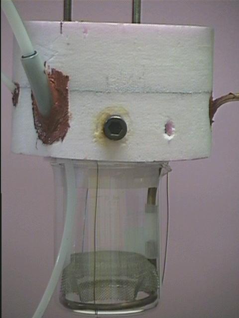
Figure 1. Image of extrusion visualization apparatus designed to prevent ice formation.
Another problem of ice formation is the tendency of the ice to form small, dispersed crystals many of which are small enough to be carried with the flows in the liquid. The crystals rise and fall randomly with the currents in the fluid, obscuring the view, and act as bubble centers adding further confusion to the scene.
Filling with liquid cryogens also creates problems when moisture is entrained in the fill process and ice crystals are created. Several direct refills poured into the glass dewar result in a cloudy view as the fine, suspended water ice crystals scatter light in an effect similar to fog. To avoid this effect a purge is maintained at all times. A gravity fill from an unpressurized supply tank to the working dewar is preferably done through a vacuum insulated line, but properly sealed polyethylene tubing works well to reduce heat conducted into the working dewar. For an uninsulated polyethylene transfer line the tubing should be at least 10 mm OD to reduce the pulsed flow complications of two phase flow. The larger diameter allows better localized cooling of the tubing as the mass per unit length of tubing drops for a given tube wall thickness as the diameter of the tubing increases.
Another fill technique involves using a phase separator (liquid from gas) and a pressurized cryogen supply. The phase separator typically takes the form of a porous sintered brass cap, but other machined equivalents can be substituted. The phase separator is at the end of the transfer line inside the working dewar. When using an uninsulated transfer line the phase separator must be submersed in the working dewar and a thermal break must be installed at the entrance to the working dewar to reduce the heat input. Smaller transfer lines have higher pressure drop and cause greater the agitation of the fluid. In some cases this increased agitation during refill may be undesirable, and either a lower pressure system or larger diameter transfer lines must be used.
Solid Argon Experiments. Argon for solidification was supplied from standard cryogenic cylinders of liquid argon, a much easier medium to use than the gas, and not expensive. The 20 ppm of impurity in the liquid is the equivalent of almost five 9's purity of the gas.
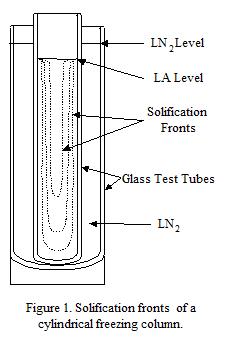
Solid argon was formed in many tests during the program by immersing a container of liquid argon in LN2. In most cases it forms a perfectly clear solid that can only be distinguished from the liquid by its different index of refraction when both are present - the boundary line between the two phases is visible. A 1 cm thick section of argon will solidify in a time on the order of 10 minutes in an uninsulated container in LN2. Solidifying a cylinder (test tube) of argon in LN2 results in a distinctive volume pattern shown in Fig. 1. Initially the solidification surface moves in from the wall at a fixed rate. As the radius decreases, freezing from the bottom moves faster and leads to the formation of a columnar volume of liquid with a cone shape at the bottom. This solidification behavior was convenient for creating a particle/argon mixture not in contact with the wall, since the particles could be poured into the liquid column surrounded by solid argon, and then the particle/argon mixture frozen.
One of the important features of solid argon for this program is its plasticity at temperatures near its melting point. Materials in general decrease in strength at high temperature, but this phenomenon is much more important for the cryogenic solids because these temperatures represent more common rather than less common conditions. The temperature of plasticity for solid argon is particularly convenient since it occurs at boiling LN2 temperatures, so that no complicated control scheme is required to operate industrial equipment at this temperature. Project work showed that the temperature of the solid argon could be even further controlled to optimize plasticity.
| Mole % Ar in Liquid |
T(K) | Mole Ar in Vapor |
| 0 | 78.9 | 0 |
| 20 | 80.3 | 7.5 |
| 40 | 81.7 | 17.8 |
| 60 | 83.5 | 32.8 |
| 80 | 85.6 | 56.5 |
| 100 | 89.0 | 100 |
Temperature Control. One of the early problems encountered in the argon solidification experiments was that LN2 and liquid argon are fully soluble, so that LN2 would contaminate the liquid argon if care was not taken. Furthermore, the heat of solution is significant, so that mixing the two liquids results in unpredictable temperatures until the mixed liquids stabilize. It soon became evident, however, that because together LN2 and liquid argon span the temperature range between boiling LN2 temperature and the melting temperature of solid argon, that a properly proportioned solution would allow simple operation at any temperature in this range. Data and experiments confirm this: Table 3 shows the dependence of the solution temperature on the mole % of argon in the mixture [9]. This is expected to be an important capability for commercialization and will be developed in Phase 2 and Phase 3.
Solid Argon Extrusion: A press apparatus was built to test the extrusion properties of argon and, later, argon/Ti particle mixtures. The apparatus was built around a 20 Ton press, and consisted of a cylindrical central compression piston moving into a cylindrical cavity. The cavity was mounted on a thick plate suspended from the press so that the entire apparatus can be immersed in LN2 for testing. A half scale drawing of the apparatus is shown in Fig. 2, and an image of the apparatus is shown in Fig. 3. Extrusion pressures as high as 300 atm could be achieved
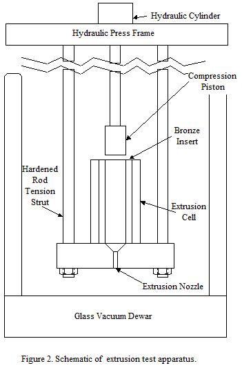
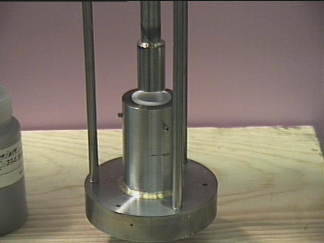
Figure 3. Image of the extrusion cell, piston, and tension support rods.
in this apparatus at LN2 temperatures. The apparatus is made of stainless steel with a bronze insert in the extrusion chamber to prevent galling. The inner sleeve is retained by a combination of set screw and sheering pins to allow for easy modifications such as changes in piston diameter. The dimensions of the aperture and cylinder were created to mimic the barrel of Thoughtventions's injection molding machine.
A series of solid argon extrusion experiments were then done. For the first test of the cryopress system, liquid argon was frozen at 77 K in the sample cylinder by immersing the entire cryopress into the liquid nitrogen transparent dewar. The bottom hole was plugged, the cylinder was filled with liquid argon, and then frozen. The argon was extruded through the hole or nozzle in the bottom of the lower plate directly into the liquid nitrogen. The system pressure was measured by a diaphragm type sensor with output interfaced to a computer data acquisition system. LabVIEW software was used to collect the data. The piston was seen to have a drag pressure in the sample cylinder of typically 0.18 MPa. The argon extruded at an average pressure of 2.0 MPa, which is much lower than the literature value of 25 MPa cited above. The reason for this difference is not known, but it is certain, based on many tests, that practical extrusion pressures are low into open cavities.
The solid argon formed clear to slightly cloudy continuous straight strands. The strands rapidly dissolved in the liquid nitrogen. Over time the visibility in the system decayed to the point where observations could no longer be made, which led to the development of extensive techniques for eliminating water ice discussed above. Extrusion of the full cylinder charge was done easily.
To preserve the strands for evaluating the life time and behavior of the solid when introduced to a mold cavity filled with gas, and to increase the viewing window size , the cryopress was modified so that extrusion into a gas could be performed. A foam cooling vessel independent from the transparent dewar used above was formed around the lower stage. This upper cooling stage then allowed a different temperature baths to freeze the sample. This also allowed a greater viewing and working space below the stage within the transparent dewar.
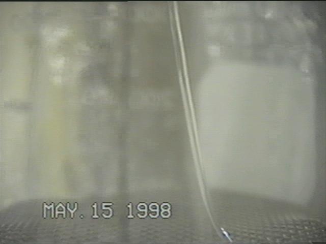
Figure 4. Image of a column of extruded solid argon.
For the extrusion of pure argon into a gas, the sample cylinder was cooled liquid nitrogen. The liquid nitrogen was placed in the foam container which surrounds the lower stage of the cryopress. The extrudate entered into a gas purged beaker which was tightly fitted to the bottom of the extrusion plate. Dry nitrogen gas was used to purge the container of ambient air as helium was not available at that time. The purge gas was warm, which shortened the lifetime of the extrudate.
Figure 4 shows an image of an argon (clear column curving right at center) strand passing into the beaker. As usual, since the solid is clear or white, it is difficult to image. In this case the solid argon curled as it entered the sample reciever. The strands could even be made to kink depending on the motion of the hydraulic pump. Replacing the hydraulic pump with a motorized pump would allow continuous extrusion of the solid. A stainless steel mesh plate was added to the bottom of the beaker to keep the extrudate from contacting any accumulated liquids in the beaker bottom. The argon solid was, again, clear to cloudy. The cloudiness being due to a rough surface.
The upper sample cooling vessel allowed different temperature coolants from that of the receiver vessel. Some tests were performed with the cooling bath at 80K, The extrusion pressure dropped lower than that of pure argon at 77 K and the solid was invariably cloudy. The extruded solids were seen to easily break up. Continuous extrusion at this temperature would be difficult as a result of time required to freeze samples.
Contamination of a sample also presented a problem, even a small amount of nitrogen in argon created a mushy cloudy slush at 77- 80K and had very poor extrusion qualities. It is standard practice in these experiments to use a small portable cooling ladle to cool the piston, in several experiments using a pure sample of argon inconsistent extrusion results were seen. It was later found that the nitrogen used to cool the piston was leaking into the sample cylinder through the bottom of the piston cooling vessel.
A final test for pure argon was its behavior when injected into a mold cavity. The transparent cryomold designed (described in Task 3) for this experiment was tightly fitted to the bottom of the extrusion plate of the cryopress. It was not found necessary to thoroughly seal the mold to the extrusion plate. A cooled helium gas purge at ~10 kPai was used to maintain a purge in the cryomold. The purge kept the liquid nitrogen surrounding the mold, incidental argon leaks, and atmospheric air from entering the mold. The sample valve was closed prior to loading the sample cylinder with argon to prevent the argon liquid from leaking through to the mold and to prevent the helium gas from preventing freezing of the sample by bubbling through the liquid.
Initial tests with pure argon indicated that the mold would need to be safety tested to full system pressures. After testing the system to 135 atm a successful extrusion test of pure argon was performed. The sample valve is opened after the sample is determined to have been frozen, then the mold fills with high pressure gas which exits through the central flashing faces of the mold, then argon strands fill the mold and begin deforming and packing. Packing of the argon increases and the mold appears to be filled with a white solid. At 80 atm the solid becomes transparent. Images of the extruded argon are shown in Fig. 5. On the left can be seen convoluted strands almost filling the mold. After further extrusion the mold becomes a milky solid, and after additional pressure is applied the argon forms a clean solid.
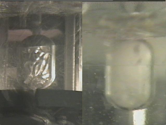
Figure 5. Image of solid argon column extruded into a mold.
Titanium Powder: There were two sources of Ti powder for the project. At this time Ti powder is manufactured only for the P/M industry rather than for MIM purposes. The P/M industry uses larger particles (100 µm vs. 10 µm) than does MIM, so the size of the particles used for this program is larger than normally used in a MIM process. Ti particles can also be different from standard MIM metal particles in that it is available as a sponge fine. Sponge particles are chemically produced from rutile ore and have a flat, convoluted shape rather than a more compact, spherical or oblong shape that is characteristic of most particle production methods such as atomization.
Titanium Powder Specialists (Sandy, UT) offers commercially pure (CP) Ti powder and a standard 6% Al, 4% V, Ti alloy in particle sizes as small as -325 mesh (less than 44 µm). The supplier was unsure what the size distribution of these particles was, but it is believed that most of the particles were in the closer to 40 µm diameter than smaller sizes. Two forms of particles were purchased: sponge was obtained first and used for most of the project, and then hydride/dehydride powder was obtained. The sponge fines were chosen initially because of their ability to compact into a piece that had significant strength under moderate pressures. The more spherical particles require much higher pressures for compaction.
An investigation was done to find a source of smaller Ti particles. One possibility was a gas atomization process used by Crucible Research. They provide both CP and TiVAl alloy as well, with supposedly a larger fraction of the smaller particles. They estimated that there would be 60 g of less than 10 m diameter particles in 150 kg of nominally less than 500 µ m diameter particles produced in their atomizers. One pound of the -325 mesh particles was obtained with the caveat that the larger particles would be returned after the smaller (< 10 µm) were removed. An interesting note to their process is that they quench the liquid droplets with liquid argon to obtain small particle sizes.
Particle Purity The central motivation for this program is to eliminate binder contamination in a Ti MIM process by using solid argon as the binder. The purity of the commercially obtained particles is shown in Table 4. In the gas atomization process, even when using four 9's purity argon gas the Ti absorbs the oxygen present to create the impurity levels that they obtain. Purity Specifications for the commercial powder were quoted as:
| Fe | C | O | N | H | Si | Na | Cl | |
| Crucible Research Powder (%): | 0.12 | 0.069 | 0.27 | 0.025 | 0.0062 | - | - | - |
| Ti Powder Specialists Sponge(%) | 0.08 | 0.03 | 0.39 | 0.02 | - | 0.01 | 0.15 | 0.15 |
| Ti Powder Specialists Hydride(%) | 0.05 | 0.03 | 0.30 | 0.025 | - | 0.01 | 0.09 | 0.09 |
These elements must be held to acceptable low levels to prevent an increase in the strength and decrease in the ductility of the final product Ti as shown in Fig. 6 [4].
The impurities shown in Table 1 range from a high of 4000 ppm for O2, to a low of 100 ppm for Si whereas the impurities contained in liquid (solid) argon are 20 ppm or less. Furthermore, these impurities would not be expected to affect the Ti, because its reactivity only begins at temperatures in the range of 600-700°C and all of the argon and impurities would be expected to be pumped away at temperatures much lower than this. Ti is known as an extremely effective vacuum getter material; this means that fresh Ti reacts with just about everything to draw it from a vacuum to very low vapor pressures.
Mixture Formation. At the start of the program it was believed that the lack of a mechanism for achieving significant green strength would be the primary problem for the project. For this reason, initial work was done with sponge Ti particles. It was thought that a sponge particle/solid argon mixture could be formed, injected, degassed at room temperature and then compacted with additional pressure within the mold to provide enough green strength for sintering. It is still believed that this concept will work. However, the use of sponge particles may have led to problems in forming the proper particle/argon mixture.
The first extrusion tests formed a mixture by loading the barrel with loose Ti sponge particles and then pouring in liquid argon, followed by freezing the argon. This mixture compacted and did not extrude. Apparently the particle density and interparticle friction was too high. Standard binder/particle mixtures consist of about 40% binder, which allows separation of the particles in the mixture and lower viscosity extrusion.
There is no temperature at which argon behaves like a viscous liquid. Although the strength of the solid decreases as its temperature approaches its melting point, it never behaves as a liquid. Standard MIM feedstock has a viscosity less than 100 Pa-s, nominally in the range of 20 - 200 Pa-s. If the viscosity is too low powder-binder separation occurs. If it is too high extrusion is not practical. To put these viscosities in the context of common liquids, glycerine has a viscosity of 1 Pa-s. A viscosity of 100 Pa-s is similar to that of a spreadable paste. The fact that solid argon does not behave as a viscous material makes standard techniques for mixing powder and binder impractical.
Furthermore solid argon will deform but not readily tear, again making it difficult to uniformly mix powder into the solid. Once this problem was evident a variety of solutions were considered, but no process that was good enough to extrude high quality parts had been developed at the time of this writing.
The practical solution that was adopted to obtain some particle/argon mixture extrusion results was to alternate solid argon freezing with particle addition. These experiments are discussed in Task 2, but the essential mechanism that allowed extrusion was that solid argon was formed first on the walls and acted as a lubricant.
Extensive work was done on finding techniques for forming uniform solid argon/Ti particle mixtures with controlled proportion. The primary direction taken was to try to suspend the Ti particles in the liquid and then freeze the mixture. Initial attempts at suspending particles in the liquid showed that the particles settled to the bottom before they could be frozen into the argon, even when the mixture was stirred while being frozen. A laser extinction diagnostic provided a quantitative diagnostic of particle loading and settling for smaller particle loadings. Since it was known that the sponge particles were significantly larger than standard MIM particles, calculations were done on the settling rate of smaller particles.
Small Particle Separation: One way to suspend the Ti particles in the Argon is to use particles small enough so that the particle settling is long compared with the solidification time. The terminal settling velocity of solid spheres in a liquid under gravity is:
ut = gdp2(ρp - ρ1)/18µ
Where g is the gravitational constant, dp is the particle diameter, ρp is the particle density, ρl is the liquid density, and µ is the liquid viscosity. This equation holds if the Reynolds number, Re, is less than 0.3; i.e. small particles in laminar flow. For Ti particles with a density of 4.5 g/cm3, Ar liquid with density of 1.4 g/cm3 and viscosity 3 mpoise, a particle diameter of 10 µm, the settling velocity is 5 x 10⁻³ cm/sec, and it will take approximately 200 sec (3 min) for a particle to settly 1 cm. Larger particles of 40 µm diameter will only take 10 sec to settle.
Preliminary experiments confirm this behavior; a visually significant fraction of the sponge particles remain suspended in liquid argon for extended periods of time. Unfortunately there were not enough of these smaller particles to perform mixing experiments with. At the end of the reporting period Ti particles with enough small particles were obtained so that mixture experiments could be performed. It is planned to remove the small particles by pouring all of the particles into the liquid argon, stirring the mixture, then allowing the larger particles to settle, pouring off and collecting the smaller particles. The concentration of these particles in the liquid can then be increased by allowing the argon to boil off. The mixture and container can be weight to determine particle/argon proportion, and when the desired proportions are obtained the mixture can be frozen for extrusion tests.
Alternate Mixing Techniques: There are a series of other possible mixing techniques that can be pursued if the liquid suspension technique fails. A solid/liquid argon slush can be made, and if the slush particles can be made small enough, continually melting and refreezing while being stirred particles can be mixed into the particles and the entire mixture frozen.
Another technique is to add particles slowly as the solid continually freezes. This appears possible but requires a mechanical means of slowly adding particles over a uniform area. Developing a device to do this would require a significant fraction of a Phase 1 program.
It may also be possible to create a solid combination that can be mixed in more standard mixing apparatus. If argon is frozen as a mist or snow the particles might be mixable with metal particles in a mixing machine. Certainly snow can be formed condensing argon in cold helium gas, but the properties of the snow are unknown. Similarly, liquid argon can be sprayed into cold helium to form small particles, but it is not known whether these particles will weld together when they pile up.
6.3. Task 2 - Binder Tests
Statement of Work: The viscous properties of the powder/binder mixture at different concentrations of binder will be measured using mixing techniques and by extruding the mixture optimized by performing mixing and extrusion tests. Extrusion experiments will be used to optimize the binder fraction.
Results: The work of this task was limited by an inability to form uniform mixtures of solid argon and Ti particles with high densities of particles, as discussed in Task 1. The general properties of these binder/particle mixtures were investigated, and some extrusion experiments were done using solid argon with varying concentrations of titanium particles.
High packing density of particles and a low mixture viscosity are optimum properties for MIM. Sufficient binder is needed to fill all interparticle voids and to lubricate particle sliding during molding. The viscosity depends on the properties of the particles, the inherent binder viscosity, as well as the mixture temperature, shear rate, solids content, and type of surface wetting agents included in the binder. The viscosity of the mixture ηm varies with the powder content φ, also termed the solids loading, and basic binder viscosity ηb.
Particles MIM particles are quantitatively defined by 1) particle shape and its variation with particle size, 2) particle size and size distribution, 3) surface area, 4) interparticle friction, 5) mechanical properties, 6) chemical properties, and 7) microstructure. To fully specify the nature of a powder it is also necessary to qualitatively describe how it was fabricated as illustrated by the peculiar properties of Ti sponge particles. When using powders, the properties of both the individual particles and the collective properties of a powder lot must be studied. For a bulk lot of powder, characterization implies measurement of the mean physical properties, packing, flow, and surface attributes. Shape is a difficult property to measure. Very different sizes are measured depending on the size parameter used and the shape itself. Usually a simplifying assumption for the shape is necessary to reduce the particle size information to a single parameter. The apparent density, or bulk, of a powder is the density (mass/volume) when the powder is in the loose state without agitation. Tap density is the highest density that can be achieved by vibration of a powder without the application of external pressure. Theoretical density corresponds to the handbook density for a powder; the density when there is no porosity present. The details of the titanium particles used in this project are discussed in Task 1.
Interparticle Friction Powder flow and packing is usually determined by interparticle friction. The friction between particles in turn is dominated by the surface area, surface roughness, and surface chemistry. As the surface area increases, the amount of friction in a powder mass increases and the particles flow and pack less efficiently. For binder/particle mixtures particle interaction is still very important, but it is strongly modified by the properties of the binder, which typically takes up 40% of the volume for MIM. For MIM the binder provides lubrication between the particles on both microscopic and macroscopic scales. There seems to be no reason or experimental evidence that solid argon cannot perform this function well. The primary question yet to be answered is how well this function is performed at high particle loadings.
Most metal powders are cohesive because of their small sizes and are not easily dispersed. Although Van der Waals forces are small, adsorbed moisture causes particle agglomeration. An agglomeration is defined as a set of particles held together by weak forces that can be overcome by applying a stress far below solid material strength. An aggregate, however, can not be dispersed easily since it is a cluster of crystals or particles held together by strong bonds, such as cementing agents. The primary concern of MIM is with dispersion of agglomerated particles. Mixing particles in liquid argon seems to solve this problem - no agglomeration was observed in numerous experiments.
Mixing Mixing is the first step in the preparation of a powder-binder feedstock for shaping. The quality of the mixture is crucial, since mixing deficiencies can not be corrected by subsequent processing. There are several problems in creating a homogenous mixture, especially at the microscopic level. Uniform quantities of the particles and binder are needed in all parts and on all scales of the mixtures used in the MIM process.
The goals of mixing are to 1) fully coat all particles with the binder, 2) to break up agglomerates, and 3) to attain uniform distributions of binder and particle size throughout the feedstock. Weight and temperature control must be precise to ensure process repeatability. High shear is required to cause molecular scale dispersion between the particles. Double planetary, single screw extruder, plunger extruder, twin screw extruder, twin cam, and sigma or z- blade mixer designs are used.
The initial action of mixing is to break apart large clusters of particles by shear. With continued mixing, the cluster size decreases as the binder becomes dispersed in the interparticle pores. Segregation can occur during mixing if the binder has a low viscosity and the powder has a wide size distribution, leading to imperfect steady-state homogeneity. Maximum homogeneity increases rapidly with time during mixing , but in some cases it can decrease again due to a resulting decrease in binder viscosity.
The inhomogeneities in a mixture occur in two main forms, separation of the binder from the powder, and segregation according to particle size within the binder. The separation of particles by size (or shape or density) leads to uneven packing densities and distortion of the final product. Small or irregular shaped particles require longer mixing times to attain homogeneity and present special problems with respect to mixing. Small particles will agglomerate, thereby increasing the time needed to form a homogenous mixture. In the presence of agglomeration, uniform mixing is difficult.
In this context, the concept of mixing particles in liquid argon appears to function well. Suspension in the liquid should occur equally well for any shape of particle, if they are small enough. Formation of uniform mixtures should be rapid, and the more rapid the better in terms of the desired permanent suspension by rapid solidification.
Mixture homogeneity is usually assessed by the size of poorly mixed regions. These regions are identified by their compositional fluctuation from point-to-point. The measure of uniformity can be based on sample density, heat capacity, electrical conductivity, or microscopic examinations. The quality of the overall mixture is assessed by comparing widely spaced samples.
Argon/Ti Mixture Extrusion Experiments: For a coaxial cooling bath and the central cylinder geometry shown in Fig. 3, argon solidifies from the bottom and the sides into a cone shape at the center as shown in Fig. 1. A number of solid argon/Ti particle extrusion experiments were performed by filling the liquid cone with Ti particles and then completing the freezing process. This process must be done with care, since dropping any room temperature 5cc or larger charge of any type of powder into a cryogen is an explosive event. Ideally the powder must be pre-cooled to the vicinity of temperature of the fluid. The hot powder particles greatly enhance the boiling to a point of violence and the evolving gases can easily displace much of the powder from the fluid surface.
Though it is a simple matter to cool the powder prior to mixing, atmospheric water and icing of the particles becomes a significant problem if sample purging is not done at all stages of transportation to the sample cylinder.
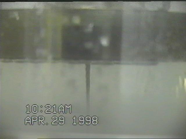
Figure 7. Image of extruded column of a mixture of solid argon and Ti particles.
Figure 7 shows a strand of such a sample being extruded directly into liquid argon. Strands of varying particle density are extruded as the piston pushes the sample through. As the particle density increases the continuity of the extrudate decreases. At the highest particle densities opaque strands of argon/Ti particles were extruded, breaking off in 3mm long pieces, or pure powder emerged falling straight through (not injected). At lower particle concentration, the extrudate had a varying diameter central core of titanium powder surrounded by a shield of pure argon. The image shown is of an intermediate-high density case where the particles have good density and the argon shield is absent.
A continuous boule of homogeneous argon/titanuim can be produced by carefully monitoring a continuous particle feed into a progressively lowered cylinder of argon. As the argon freezes while being lowered into the cooling bath the powder is continually added into the cylinder. Good examples of the potential for forming a boule were prepared in test tube bench top freezing experiments.
Some testing was performed with isopropyl alcohol. This room temperature liquid turns to a gelatinous consistency prior to freezing to a hard icy solid 77K. The partially solidified substance was seen to be easily extrudable at elevated temperatures. Alcohol also can be readily prepared with very high particle loading.
6.4. Task 3 - MIM/Debinding Tests
Statement of Work: MIM techniques for the binder/powder mixture will be demonstrated and explored by using a standard screw injector and a cylindrical mold. Titanium MIM powder parts will be made. A satisfactory process by which the binder is removed will be defined.
Results: MIM experiments centered on extrusion of solid argon/Ti particle mixtures into a transparent mold to observe the extrusion process. A two-part plexiglas mold shown in Fig. 8 was machined and polished to be able to see the argon and particle mixture fill the cavity to investigate mold filling. The mold has a runner and a 2 mm gate similar to a standard MIM, and was attached to the extruder. The mold was tested first with only solid argon as discussed in Task 1 and shown in Fig. 5.
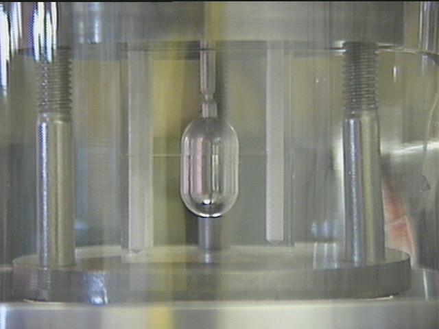
Figure 8. Transparent mold used for extrusion testing.
A variety of transparent materials were considered for the mold cavity. Desirable properties were that it be low cost, easily machined, easily polished, strong, and capable of surviving the repeated temperature cycling from room temperature to the design injection temperature of 77K. Initial efforts focused on using curing liquid plastics, since these materials would minimize machining, have good stength, and they could be used to form mold cavities which would not need polishing. Polyester resin and polyurethane were investigated, but these castable 2 part systems created parts that shattered an their first immersion into liquid nitrogen. The material selected was cast acrylic. The acrylic survived repeated cryogen immersions and was highly shock and impact resistant at room temperature and design temperature. Compression tests were performed on the material for overall strength as compared to the anticipated pressures. The central cavity was polished with buffing wheels embedded with diamond pastes and the exterior faces of the two mold halves were polished on a rotary plate polishing machine on buffered pads embedded with diamond paste. A very high quality finish was attained with this technique.
Injection molding of solid argon/Ti particles was attempted near the completion of this report. Tests were performed using the sub-325 mesh titanium sponge mixed with argon. A 2 gm charge of the powder was added to freezing argon in segments. When the sample was frozen the piston was lowered and a mix of visually high particle density extrudate entered the cryomold. Although some packing was thought to be seen, it was decided that additional pressure safety tests should be performed before applying higher pressures to achieve good packing. This test went to 100 atm before being terminated. Dry pellet tests early on in the program indicate that typically 250atm pressure are required to obtain good strength pellets which hold their shape after return to ambient pressures. The first high pressure test reached 260 atm, however it is not certain that the measured system pressure was transferred into the mold cavity. The mold appeared to be filled with Ti particles, but one test showed much less powder once the argon evaporated, and another test, while achieving better filling, still had no strength. The powder density may be too low, or the powder may be moving back into the sample cylinder after release of pressure and warming. More tests are planned.
Figure 9 shows images of the extruded mixture filling the mold. On the left can be seen strands beginning to fill the mold after entering through the gate. The strands have the diameter of the gate and have a high enough particle density so that they are opaque. The image on the right shows the mold filled with the argon/Ti particle mixture. Since the mixture was not uniform in the extrusion barrel, the final part has a varying particle density.
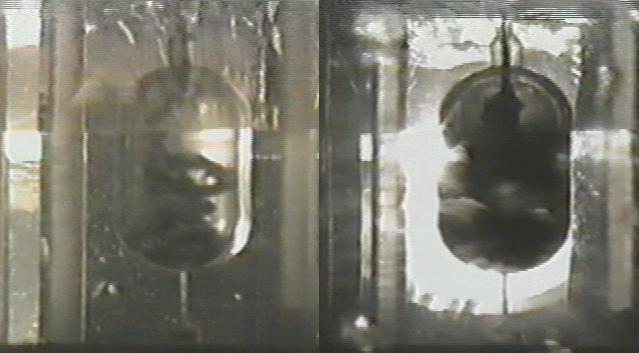
Figure 9. Images of solid argon/titanium particle mixtures being extruded into a mold.
Lubrication Friction between the die wall and the powder during pressing is a fundamental problem. As the compaction pressure is increased, ejection of the powder mass from the die becomes more difficult. Consequently, lubricants are used to minimize die wear and ease ejection. There are two means of lubricating a pressing; die wall and powder lubrication. Die wall lubrication is preferred in theory, but is not easy to incorporate into automatic compaction equipment. Thus, lubricants are usually mixed with the metal powder as a final step before pressing. During deformation, the lubricant forms a fluid that lowers friction by creating a thick film of high viscosity polymer. Thus, lubricants are usually mixed with the metal powder as a final step before pressing. During deformation, the lubricant forms a fluid that lowers friction by creating a thick film of high viscosity polymer. Low viscosity fluids are not effective since they will be forced away from the friction points by the high pressures used in powder compaction. Adding a lubricant will almost certainly not be practical for an argon binder used with a reactive metal, but experiments to date indicate that argon may work by itself. More work needs to be done on this issue.
Debinding Debinding is chemically straightforward for a solid argon binder. There are no polymers to break or any chemistry at all to contend with. This is one of the most attractive characteristics of using argon as a binder. Debinding can take place at a rapid pace at almost any temperature above the freezing point, but at temperatures close to the freezing point the cooling associated with evaporation may delay the process. It is possible that vacuum sublimation is a attractive route for other reasons, such as obtaining green strength as a result of vacuum contact welding. This might be even be done in the mold. For energetic reasons and to recycle the argon the best debinding technique would be in a heat/mass exchange system after the part was ejected.
Green Strength One of the key questions of the entire Phase 1 program was to determine if solid argon MIM parts could be made with sufficient green strength to tolerate the handling requirements of the standard MIM process. This requires that once the mold has been filled, the part must be able to be automatically ejected from the mold and then transported to a furnace for debinding and sintering.
Green strength can be achieved in a number of ways, but because of problems encountered in forming an extrudable mixture, the issue of green strength could not be addressed experimentally by the time this report was written. A number of concepts for providing green strength were assessed, however. These were 1) Contact welding, 2) Transport to the furnace with the solid argon still in the part, 3) Compaction in the mold after mold filling, and 4) Surface binders..
Contact welding usually occurs when very clean metals surfaces are brought together under vacuum. The welding between the surfaces results from atomic scale metal-to-metal contact and bonding. In the present case, if the reactive metals have contamination-free surfaces the argon binder would be inert enough to allow the contact welding. There was no evidence of this effect in compaction/extrusion experiments. Green strength was found to be essentially zero unless the sponge particles were compacted. Special particle cleaning processes, such as sputter cleaning or acid washing were not attempted.
The lack of green strength was evident if the part was transported containing solid argon. Although solid argon melts/sublimes on time scales on the order of seconds in air as a result of its relatively poor thermal conductivity, the argon in the Ti/argon part evaporates much more quickly as a result of the higher thermal conductivity of the Ti. The argon would evaporate from the outside of the part and the particles would slump off under the forces of gravity. This slumping would make flash sintering of the outside of the part also impractical, another possibility considered for achieving green strength at the start of the project.
The technique of compaction in the mold to provide green strength appears promising based on Phase 1 experiments with the sponge particles. A part made from sponge particles was found to stay together after compression to 26 MPa, a pressure easily attainable for injection molding apparatus, and well above the pressure required for extrusion. If the injection molding process were modified such that the argon from the outside of molded Ti/argon part were allowed to evaporate, an additional pressure increase from the injection machine would compact the outside of the part and provide adequate green strength for handling. The compaction should leave more than enough porosity for the remainder of the argon to evaporate. This processing appears practical and will be attempted experimentally, but it relies on the use of sponge.
The use of surface binders was also considered, but it was felt that such a process would add too much complexity to the overall process to be practical.
Dry Compaction Tests: A series of dry compaction tests were performed to obtain information about forming parts out of sponge Ti particles. It was known that Ti sponge forms cohesive compacts at much lower pressures than spherical particles of Ti, and it was (is) hoped that this property could be used to achieve green strength for the proposed MIM process. A series of powder cylinders were compacted. It was found that cylinders compacted to 135 atm were strong enough to handle but weak; the edges would rub off under gentle pressure. At 400 atm the cylinder could not be broken. Distortion and interlocking give the compact strength. This data provides a guide for the pressure needed to give the molded argon/Ti parts strength after some (or all) of the argon is evaporated.
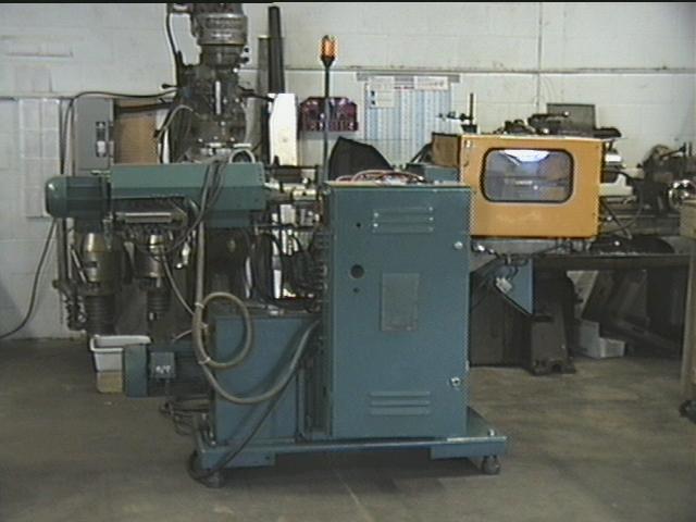
Figure 11. Commercial injection molding to be modified.
Injection Molding Machines Modification for Cryogenic Injection. A used BOY 15/7, 140 bar injection molding machine shown in Fig. 11 was purchased with company capital equipment money and refurbished during the project. The machine has been successfully tested for hydraulic functionality.
This machine will be modified to use the solid argon binder system. Initial design modifications on the injector side involve a single shot re-loadable charge, replacing the screw feed (which is used for continuous feeding) with a simple piston, and adding a new nozzle. All components subjected to cryogenic temperatures would be made of stainless steel for initial tests. Alternative materials and coatings would be considered for production machines. The mold platens would also be of stainless steel.
Cooling tests were performed on large (2 in. diameter x 7 in. long) billets of stainless steel to determine the best technique to adequately cool the modified barrel components. This size sample was representative of the size of the existing standard barrel components and had greater mass. Both indirect cooling via conduction and immersion cooling were tested. Indirect test involved soldering copper cooling lines with flowing LN2 as the coolant. Though these tests went well the billets could not be brought near the normal boiling pt temperature of the nitrogen. The jacketed immersion system is superior in efficiency in that it can maintain low temperatures without the significant 2-phase flow problems encountered using cooling coils.
Based on the jacketed immersion cooling a design for the mold was made. The mold would be a styrofoam insulated die with a large cooling pocket in it. The pocket would be in direct contact with steel of the mold cavity. And have line in and out feedthroughs and vents passing through the moving platen into the die plates. The barrel components would have coaxial cylindrical chambers soldered or welded to each segment and also have a coolant feed purging and venting lines (9.5 mm OD. tubing would be adequate.) Cylindrical insulation jackets would surround these chambers.
6.5. Task 4 - Sintering Tests/Feasibility/Phase 2 Plan
Statement of Work: Preliminary sintering tests that demonstrate the quality of Ti MIM parts will be attempted. The overall feasibility of the new binder will be assessed based on how well and easily it can be adapted to the MIM process and whether it is cost effective. A plan will be developed to define a Phase 2 prototype process.
Results: Most of the work of this task has been to evaluate the potential of the process, since difficulties with forming proper argon/Ti particle mixtures prevented the formation of extrusion molded parts.
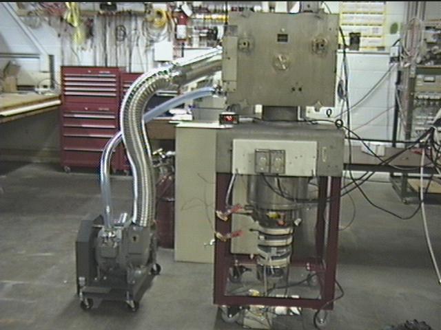
Figure 12. Tungsten hot zone vacuum furnace used for titanium part sintering.
Sintering Tests: Pellets of dry-compacted Ti sponge were sintered for 2-4 hours at 1260°C in Thoughtventions's tungsten metal hot zone furnace shown in Fig 12. This used furnace was purchased as a shell with elements at the start of this project using Thoughtventions's capital equipment funds. The furnace was refurbished, a supporting vacuum system was assembled, the furnace vacuum was debugged, the furnace was baked out, a power supply was added, and the furnace was tested. The quality of the vacuum was monitored using a Residual Gas Analyzer (RGA). The sintered parts were inspected using a light microscope and Thoughtventions's SEM. Sintering appeared to be taking place as expected, but since the parts had been compacted to high density before sintering, detailed evaluation was not done because the sintering was not representative of what would occur in a MIM part.
MIM parts commonly go through the debinding and sintering process in a single cycle. When molded parts are formed they will then undergo debinding and sintering at temperatures characteristic for titanium powder (1280oC, 10 hrs). Thoughtventions is developing visual access to its furnace, and this will be used to study the process when it is available. The results of sintering the MIM part will be evaluated in the standard manner - densification, cracking, surface finish, etc.
Feasibility Assessment: At the writing of this report Phase 1 feasibility had clearly not been demonstrated as a result of difficulty in forming the proper Ti particle/argon mixture.
The overall feasibility of the new binder must be assessed based on how well and easily it can be adapted to the MIM process. To be feasible, the binder system must 1) form an appropriate mixture with the metal particles, 2) form a mixture that can be injected into a mold without defects, 3) form a green part which has sufficient green strength for handling, 4) form a part from which the binder can be easily removed before sintering, 5) forms an uncontaminated part for sintering, 6) leads to a high quality part, and 7) is cost effective. All of these demands must be satisfactorily met to demonstrate feasibility.
Current MIM Parts: An important part of considering the feasibility of the process is to compare it with standard MIM parts to determine its relative strengths and weaknesses. The MIM process is complicated and its equipment is complex and expensive.
The process begins by mixing selected powders and binders. The particles are small to aid in sintering densification, and usually have sizes in the range of 0.5 to 15 µm with near spherical shapes. The powder-binder mixture is normally granulated and injection molded into the desired shape. The standard polymer imparts viscous flow characteristics to the mixture to aid forming, die filling, and uniform packing. After molding, the binder is removed and the remaining powder structure sintered. The product may then be further densified, heat treated, or machined. The sintered compact has the shape and precision of an injection molded plastic, but is capable of materials performance levels unattainable with polymers.
After molding, the binder is removed from the compact either by thermal, solvent, or capillary extraction methods. For metals, thermal debinding is frequently used, where the compact is heated slowly to approximately 600°C in air to decompose the binder and oxidize the particles. The oxidation process provides handling strength to the compact. An alternative is to immerse the compact in a solvent that dissolves one of the binder constituents, leaving some polymer behind to hold the particles in place. The next step is sintering, which can be incorporated directly into the debinding cycle. Sintering provides strong interparticle bonds and removes the void space by densification. Isotropic powder packing allows for predictable and uniform shrinkage, so the original compact is oversized as appropriate to reach the final compact dimensions. After sintering, the compact has good strength and good microstructural homogeneity with overall properties superior to many other processing routes.
The injection molding step usually involves simultaneous heating and pressurization of the powder/binder mixture. The mold filling rate, maximum pressure, mixture temperature, and hold time under pressure are important variables that must be controlled during the injection. The mixture is typically heated in the barrel of the molding machine to temperatures between 130 and 190°C to achieve the proper viscosity. The molding occurs with a forward thrust of the screw in the barrel to inject a preset volume of fluid feedstock into the die. The powder mixture flows from the nozzle at the end of the barrel through the sprue, runner, and gate prior to filling the die cavity. Since the remaining material must be kept in the barrel, the mixture in the tip is frozen as a plug; pressure during the injection process liquefies it. The tooling is normally cooler than the feedstock, so that the viscosity steadily increases during the mold filling cycle, requiring a pressure increase until the cavity is filled. Pressure liquefies the mixture in the nozzle; the injector barrel might be held at 175°C while the die is at 40°C. The actual molding pressures are dependent on the die geometry, binder, and powder characteristics.
Current MIM is done primarily ferrous alloys with a limited copper base. There is a part size limitation for MIM relative to general Ti P/M; part size ranges 0.0005 lbs. to 0.22 lbs. MIM parts are usually complex, since uniaxial parts are cheaper to press. Part tolerances are typically held to 0.08 mm/mm, with a surface finish of 5 RMS. Normal minimum section thickness is about 0.4 mm for small areas. Parts are usually made in quantities of 10,000; this is an inherently high volume/low cost process.
Although there are many factors affecting cycle time, for MIM processing that uses a thermoplastic binder, cycle times for injection molding vary from 5 - 60 s, and are typically 20 s. For an overall processing time for a MIM part of 40 s, mold cooling accounts for 18 s. Mold filling is done at rates on the order of 1.5 cm3/s with a peak shear rate of the mixture is about 104/s. Binder/particle mixture viscosities are typically on the order of but less than 100 pa- s. Mold pressure is typically 8 - 15 Mpa (80 - 150 atm), but can be up to 60 MPa (9000 psi), with process temperatures up to 200°C.
MIM Molds Most PIM components are made in tool sets with 1-8 cavities. Successful mold design is complex and highly sophisticated. The basic geometry is for an injection gun to pass material through a sprue to a runner and then through a gate to the component. A typical sprue bushing is 4-6 mm in diameter with a 5° taper.
Large runners allow fast filling, typically having a 3-6 mm diameter. Gate diameters are typically 1-4 mm in diameter, with an area of 4-12 mm, where usually the length is equal to the thickness of the gate. Gates for plastic casting are small compared with MIM. The small gate opening is designed to freeze before the material in the cavity, runner, or sprue does. This allows the pressure in the machine to be taken off as the component cools. Gate sizing requires careful design, and depends on shear rates.
A typical MIM mold has a vent at the end of the cavity opposite the gate that varies from 0.015 mm deep to 12 mm wide all the way to the mold surface. MIM flash is formed in this cavity and is usually rich in binder. Molds are made from wrought stock, and the life of plastic molds is typically 1 million cycles, whereas PIM molds only last for 100,000 cycles.
MIM Part Properties. MIM parts maximize strength efficiency and metallurgical stability at elevated temperature. They have low cycle fatigue, achieving low creep rates and predictable behavior with respect to stress rupture. The parts have controlled, homogenous microstructures, with few melt imperfections. Fracture toughness is also predictable at cryogenic temperatures. Interstitial elements such as N and C are carefully controlled to improve ductility & fracture toughness. MIM parts include porosity and small inclusions, although these inclusions do not affect static material properties as much as the microstructure of the material. PM parts (including MIM) are easier to machine although a primary attribute of the MIM process is its elimination of many secondary operations such as grinding and machining.
There are a number of drawbacks inherent in current MIM processing. These include feedstock shrinkage during cooling in the mold, and the need for heating and temperature control of the injection barrel and mold. Linear shrinkage during sintering is typically 15%, and extensive work is done to calculate the effect of shrinkage.
Particles and particle/binder mixture is relatively expensive, driving MIM applications to high value parts.
Solid Argon MIM Process Assessment: Based on Phase 1 work an assessment of the solid argon MIM process can be made in the context of the above discussion of standard MIM processing. For the most part a MIM part using solid argon should have all of the standard properties of MIM parts, assuming a technique can be found for achieving uniform particle/argon mixtures. Certainly the particle/argon mixture is easily extrudable and fills a mold. An overall description of the advantages and disadvantages of the process is:
Process Advantages:
- High purity
- Total binder inertness
- Room temperature debinding
- No heating required, no heating control required, no cooling control required.
- Rapid debinding/no clogging/no special debinding cycle required
- Reduced hazard from handling small metal particles
Disadvantages
- Novel process.
- Safety hazards of cryogens, inert gases.
- Reduced equipment access due to insulation.
Research to Do: To be certain of process feasibility a number of details of the process must still be tested, although the final process can be described in detail (see Phase 2 Plan below). The primary technique that must still be developed is forming the particle/argon mixture. Progress toward this goal is discussed in Task 1. Once this is done, extrusion tests must be done to determine the optimum mixture proportions, which are likely to be different for sponge relative to standard particles. Because the argon has no temperature where it behaves like a viscous liquid, its behavior in an extrudable mixture may be fundamentally different from standard binders. It may be that contractions (such as passing through a gate) must be avoided in the injection process to eliminate interlocking jamming of the flow due to the shape of the sponge particles. Once the mixing technique has been developed, extrusion testing must demonstrate proper flow of the mixture into the mold.
Another issue that must be explored experimentally is that of the lubrication between the mixture and the die wall during pressing. Adding a lubricant would defeat the characteristic process purity. Mold filling tests will have to be done to determine if this is a problem. Part ejection tests must also be performed.
The final issue is that of green strength. The wall compaction technique discussed below for achieving green strength must be demonstrated and an optimum pressure time history to achieve this effect must be defined. The degree of compaction required must be determined, together with its dependence, if any, on part geometry.
Issues of practical detail that must be worked out include the details of injection molding machine modification and cooling power recovery for improved efficiency.
Cost: One major question is the cost effectiveness of the process. The MIM process is used because it can make large numbers of net shape parts rapidly and inexpensively. The use of a cryogenic binder can not be immediately ruled out because of cost. One way of lowering the cost of cryogens would be to perform the MIM process in a closed, insulated system, where the system can be kept at low temperature, and the ingoing material can be cooled by the outgoing parts. The need for cooling will then depend on the heat efficiency of the material transfer process and the heat generated during injection and molding. Injection molding is not naturally a low energy process, requiring elevated pressures and temperatures in most situations. In the case of an argon binder, the heating is replaced by cooling, and there is a great potential for low pressure forming, possibly leading to comparable cost for the cryogenic argon binder process.
| N2 | Ar | |
| Density (g/cc) | 0.8 | 1.4 |
| Heat of vaporization (J/kg) | 200,000 | 163,000 |
| Specific heat (J/kg-K) | 1040 | 523 |
| Cost ($/kg) | 0.42 | 0.82 |
An analysis of the cost for cryogenics is as follows. For the supply of cryogenic liquids a dewar costs 45$/mo rental and contains 230 liters (l). Specific costs are: for LN2 a dewar costs $79, implying a LN2 cost of 0.34 $/l, for LA a dewar costs $265, or 1.15 $/l. The cooling power data for A and N2 is shown in Table 5.
Calculations of the cost per part were done and need to be verified and refined from professionals in the industry. Consider a typical MIM part with a volume of 20 cc and a mass of 100 g. Titanium has a density of 4.5 g/cm3, a specific heat of 0.125 cal/g/°C (0-100°C) and 0.072 cal/g/°C at 100 K for an average value of 0.1 cal/g-C, or 400 J/kg-K.
To cool the material in the sample Ti part to 77 K from room temperature (300 K) then requires about 6,000 J. Assuming the part is cooled half-way down using the specific heat of the LN2 boil off vapor implies 280 kJ/kg, or 21 g of LN2, costing 0.9 cents/part. It is not clear how much argon needed - if 40% loading of solid argon is used as a binder (a typical concentration) then 8 cc solid argon are required, about 11 g, which would imply 0.9 cents/part. At a cost for Ti particles of 25$/lb implies 0.01 $/g, 1 cent/g, or 20 cents per part. Normal Ti P/M particles cost 5$/lb which would imply 4 cents/part as a target value for Ti particle producers (one not anywhere near to being met at present). Thus, for current costs of Ti particles, cryogen cost would be small, but would be a significant factor if particle costs decrease. Offsetting this is the recapture of cooling, which could increase the efficiency of using the cryogens by 50%. It should be kept in mind that fabrication of the mold is typically 80% of the cost of a MIM part, while the material is 5%, so the cost of cryogens should be acceptable.
Another factor is the cost of heat losses. Multilayer insulation (MLI) at atm pressure has a thermal conductivity of 0.04 mW/m-K [10]. For a delta T of 220 K, this insulation implies 9 mW/m2, or 0.009 W/cm2. Assuming 0.01 W/cm2, an injection molding barrel plus die might have a surface area of 20 x 20 x 50 cm = 2 x 104 cm2, which implies 2 x 10² W. For a processing time of 20 s/part, this implies 4 x 10³ J, or about 1 cent/part. This is probably an overestimate.
Capital equipment cost should be minimal, since commercial injection molding machines can be converted to this process without major modifications. Sintering equipment will be unchanged, except that there will be no need for a separate debinding cycle. The elimination of this process step makes the overall process much more economically attractive, since the time required for debinding is large with commensurate costs for equipment use.
The overall conclusion is that the proposed solid argon MIM process is economically attractive.
Phase 2 Prototype Process. A Phase 2 prototype MIM process using an argon binder was taking shape at the end of the reporting period. This process consists of the following steps:
- A volume of liquid argon is mixed with approximately 5 µm mean diameter Ti sponge particles in a predetermined proportion.
- This liquid particle mixture is frozen to a solid before the particles undergo significant settling.
- The mixture is either continuously frozen in the barrel of the injection molding machine or fed into the barrel in a frozen state by compression.
- The barrel maintained at a predetermined temperature between 77 K and 83 K, as desired, by using as a coolant a controlled proportion mixture of liquid argon and liquid nitrogen. The mold is kept at a higher temperature.
- The Ti/argon mixture is injected into the mold wall at a relatively low pressure.
- The argon on the outside of the part near the mold evaporates as a result of the higher mold temperature.
- A significantly higher pressure is applied to the formed part in the mold, compressing the outside and giving the part enough green strength for handling.
- The mold is separated and the part is ejected.
- The part is allowed to warm to melt/evaporate all of the argon binder.
- The part is then transferred to the sintering furnace and sintered.
Work that remains to be done to define the feasibility of this process is the following.
- Produce 5 µm mean diameter Ti sponge particles. This can be done by mixing a larger particle size range with a liquid and decanting the liquid that has the small particles still floating in it. Commercially this can be done using a small liquid cyclone separator.
- Verify that these small particles can be added to liquid argon such that the mixture can be frozen before the particles settle. Calculations described above indicate that this is feasible, but it needs to be experimentally demonstrated. There must be a maximum thickness for freezing, which needs to be determined. It should be larger than 5 cm, which is large enough to make the freezing practical.
- Determine the optimal particle loading in the solid for injection. This should be a simple matter of attempting a variety of particle loadings, and using a bit less than the maximum loading that allows extrusion. This is a standard MIM binder development technique.
- Test the injection process with the extruder/mold developed during Phase 1 using the hand press. Inject the mixture into the mold, allow the outer argon to evaporate and then further press for compaction and green strength.
- Sinter the injection molded part.
- Evaluate the part.
At this stage Phase 1 feasibility is probably demonstrated. Phase 2 will then consist of optimizing the process and: - Modify the injection molding machine for cryogenic operation.
- Perform the injection molding automatically using a realistic part.
- Evaluate the part.
- Commercialize the process.
Work will continue to develop this process. Once a part can be produced a Phase 3 partner will be approached and a Phase 2 proposal submitted.
7. CONCLUSIONS AND ESTIMATE OF TECHNICAL AND ECONOMIC FEASIBILITY
7.1. Conclusions: At this writing work on the Phase 1 program to develop a solid argon binder has resulted in significant progress, but feasibility has not yet been demonstrated. Techniques have been developed to solidify both argon and argon/particle mixtures in a manner appropriate to an injection molding process. By itself, solid argon has been shown to be easily extrudable, and it has been shown to completely fill a mold. Some particle/argon mixtures have been extruded, and extruded into a mold. However, uniform density mold fills have not yet been successfully done as a result of difficulty with forming uniform Ti/argon mixtures with controlled Ti and argon proportions. Techniques for forming such mixtures have been developed but not tested yet, requiring smaller particles than were available commercially for the project. A technique has been developed but not tested to achieve green strength of a molded part using sponge titanium particles. Overall, a demonstration of process feasibility after more work seems likely, and this work will proceed using internal funding.
7.2 Technical and Economic Feasibility: Technical Feasibility: - Phase 1 experiments have progressed toward a demonstration of technical feasibility for a solid argon MIM process, but work remains to be done on achieving uniform extrudable mixtures and achieving part green strength. There seems to be no fundamental problem with developing the proper mixing techniques, but extrudability of these mixtures and green strength must be experimentally demonstrated. Conceptual solutions to these problems have been developed.
Economic Feasibility - Economic feasibility is implied by an analysis of the cost for cryogens required for the production of each part to perform the cooling required by the process. There is no major capital investment that needs to be made; current commercial injection molding machines can be adapted to the process. Economically the process appears feasible.
7.3. Anticipated Benefits: The primary benefit of a solid argon MIM process would be the ability to make high quality titanium injection molded parts.
Technical Benefits: The primary technical benefit of a solid argon MIM process is the ability to make contamination-free titanium injection molded parts. Since the properties of titanium and its alloys degrade with the addition of only small amounts of impurities, it is important to be able to perform powder metallurgy processes without introducing contamination from the atmosphere or some processing medium. Atmospheric contamination can be eliminated by vacuum processing; the only other truly inert processing medium is an inert gas such as argon. The fact that solid argon at temperatures near its melting point behaves as a plastic allows it to be used as a binder for injection molding. MIM processing allows large volume production of complex parts to near net shape.
Economic Benefits: The capability of doing reactive metal injection molding will expand the already large powder metallurgy industry, leading to the availability of more complex reactive metal parts in the many applications where they have major advantages. The availability of a process to make large volumes of inexpensive titanium parts will greatly extend the application of this metal, leading to lighter, stronger, more fuel efficient vehicles of all types, cheaper sports equipment, as well as much less expensive medical implants, to cite a few examples.
7.5. Potential for Applications: The commercial PIM market in the US is estimated to include 40 companies with combined annual sales on the order of 400M$ and an annual growth rate of 22%. These companies process well over 50M tons of powder annually. Sixty-five percent (65%) of the products produced are metal, 30% ceramic, 5% carbides. Worldwide PIM sales are estimated at 240M$. The market is expected to grow to 2B$ by the year 2010. Market sectors for which parts are currently being manufactured include automotive, recreation, appliances, medical (surgical, dental, eyewear), business machines (disc drives, fax machines, cameras, copiers), microelectronics, aviation, and aerospace. Federal use of PIM is already widespread, forming the foundation for many military and civilian applications. The advantage of (near) net shape part production is instrumental in minimizing both the cost and the production time of new parts.
Reactive metal parts are currently extensively made using dry powder metallurgy processes, clearly demonstrating the cost effectiveness and value of such processes. Development of a contamination-free MIM process would take a significant part of this market and expand it into high volume applications. Titanium and other light alloys are in increasing demand in the aerospace, medical, military, and commercial sectors. Another testimonial to the potential of the market is the money spent on competing Ti MIM processes, which have not yet succeeded.
Acknowledgements
This material is based upon work supported by the National Science Foundation under award number 9760106. Any opinions, findings and conclusions or recommendations expressed in this publication are those of the author and do not necessarily reflect the views of the National Science Foundation.
8. REFERENCES
1. R.M. German and A. Bose, Injection Molding of Metals and Ceramics Metal Powder Ind. Fed., Princeton, NJ, 1997.
2. R. M. German, Powder Metallurgy Metal Powder Ind. Fed., Princeton, NJ, 1994.
3. R. M. German, "Variations in the Essential Powder Injection Molding Processes," Business Opportunities in the Emerging Markets for Injection Molded Metal, Ceramic and Cemented Carbide Parts, Gorham Advanced Materials Institute, Monterey, CA, (1989).
4. M.J. Donachie Jr, Titanium, A Technical Guide ASM International, Metals Park, OH, 1988.
5. F.H. Froes and and J.R. Pickens, "Powder Metallurgy of Light Metal Alloys for Demanding Applications," J. of Metals, Jan., 14 (1984).
6. Metal group drafts powder metallurgy titanium alloy structural component specification," ASTM Standardization News, 18, 19 (1990).
7. G.A. Cook, Argon, Helium and the Rare Gases Interscience, New York, NY, 1961.
8. J.W. Stewart, "..," Phys. Rev., 97, 578 (1955).
9. V.G. Fastovskii and Y.V. Petrovskii, "..," Zhur. Fiz. Khim., 30, 76 (1956).
10. K. D. Timmerhaus and T. M. Flynn, Cryogenic Process Engineering Plenum Press, New York, NY, 1989.