AUXILIARY OPTICAL HEATING FOR CONTROLLED CRYSTAL GROWTH
STEPHEN C. BATES, KIM S. KNIGHT
Thoughtventions Unlimited LLC, 40 Nutmeg Lane, Glastonbury, CT 06033
The use of auxiliary optical heating to control melt solidification crystal growth is described. Radiant heat was transported into the center of a transparent furnace hot zone through quartz fiber optics to a thin, optically absorbing susceptor surrounding the growth ampoule. The heated susceptor was used to control the growth interface shape in the melt zone in CsCdCl3 crystal growth experiments.
1. Introduction
One major issue of the growth of single crystals is the external control of the temperature surrounding the phase change interface. The work described here uses optical heating of the material near the interface to improve local temperature control for solidification crystal growth. Most crystal growth apparatus use electrical heating elements to establish the temperature gradient imposed on the crystal growth material. These heating elements are separated from the crystal material by a material container that can blur the effect of heater temperature changes.
An improved method of heating the local area around the crystal interface would deposit differential heat fluxes directly into the crystal to create and control more accurate temperature gradients. One technique for doing this is to transfer optical heat either to the crystal directly, or to a surrounding nearby susceptor. This heating is superimposed on the overall furnace temperature profiles and can be applied to the ampoule/crystal without affecting the heater coils. The optical heat can be imposed at the growth interface, so that the maximum control of the temperature and heat flux at the interface can be achieved.
The experiments described herein were designed to establish the capabilities of fiber optic auxiliary optical heating for controlling crystal growth. The goal of this work has been 1) to demonstrate that optical heating can change the local furnace temperature at the growth interface enough to effect the crystal growth process, 2) to show that crystal growth may be improved using auxiliary optical heating, and 3) to demonstrate that a practical method of optical heating exists that can satisfy the constraints of crystal growth systems.
2. Auxiliary optical heating
2.1. Capabilities and Limitations of Auxiliary Optical Heating
Optical heating can improve crystal growth processes through its ability to: 1) Transfer heat directly to the crystal irrespective of surrounding thermal gradients and surrounding materials, 2) Deliver heat to an arbitrarily shaped, localized area, 3) Create local heating in the melt to remove secondary nucleation sites during crystal growth, and 4) Act as a localized heat sink using radiation cooling at high temperature. The ability to provide a local heat input can be used to adjust local imperfections in the furnace temperature profile.
Limitations of optical heating include: 1) Long term stability of the radiant sources, 2) Uniformity of the circumferential distribution of the heating, 3) Heating efficiency, and 4) Temperature limitations of fiber optics. Adequate stability and uniformity are well within the capabilities of current commercial technology, and heating efficiency, even if poor, is not a major issue, since the optical heating only uses a small fraction of the primary heating power. It should be noted that quartz fibers can be used well above 1000°C and sapphire fibers to 1500°C.
For heating purposes, other important source parameters include lifetime and overall energy efficiency. Lamp sources are already used for industrial heating, whereas lasers now have lifetimes and efficiencies that make them a practical radiant power source if an appropriate value-added application exists. Lamp heating was used for this work to minimize program costs.
2.2. Radiant Power Delivery.
The radiant power applied to the crystal must be efficiently collected from a stable light source and delivered to the solidification zone without affecting other functions of the apparatus. Crystal growth requires a heat source that is stable within a fraction of a percent over a period of more than a few days - on the order of 100 hours. Filament lamps can fulfill these requirements, as can some lasers, especially with feedback stabilization based on a sensed radiant output. Arc sources as well as many types of lasers are less stable. Efficient light collection and transfer from a lamp bulb is accomplished by using an elliptical reflector that captures and focuses a large solid angle of the lamp radiation (Fig. 1). The mirror has a dimension large compared with the size of the long lamp filament to minimize defocussing caused by the finite size of the light source.
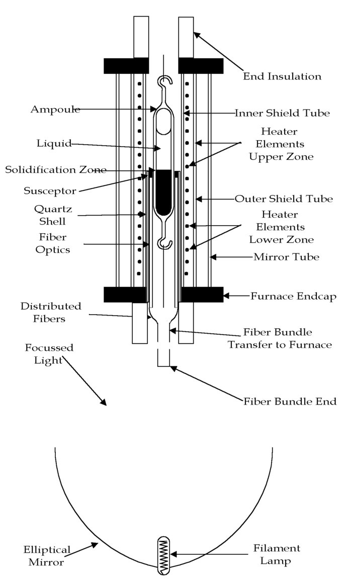
Figure 1. Schematic of the auxiliary optical heating apparatus, transparent furnace, and ampoule used for crystal growth experiments.
Fiber optics provides a way to distribute the light with high precision from a small-area source into an annulus around a crystal. It provides a means for transporting the light from a source external to the furnace into the center of the furnace without disturbing the existing thermal profile. Furthermore, in the case of a transparent furnace this can be done while maintaining most of the radial optical access by bundling the fibers as they pass axially to the center of the furnace, where they can be distributed to provide a uniform azimuthal source.
The uniformity of the radiant heating is limited by the fiber density around the periphery of the ampoule and the uniformity of the radiation entering the bundle. Using fiber optics that are 10-40 µ m in diameter implies that many fibers can be placed in a narrow zone to achieve a uniform axial and azimuthal radiation distribution. Uniform illumination of the bundle face can be achieved either by using a light diffuser for a lamp source, or a beam shaper in the case of a laser.
Appropriate spatial uniformity of the radiant heating is difficult to achieve, especially in the case of crystal growth in an ampoule, which requires azimuthal uniformity of the heating. For standard furnaces fiber optics can be used not only to transfer light between arbitrary locations, but also to change the shape of the effective source from the input to the output. One example is microscope illuminators that begin with a circular fiber bundle input, and end with a thin ring light output that is created by distributing the fiber output ends at a specific radius. A great deal of progress has also been made in the production of light sources that are uniform within a few percent over large areas using a variety of sophisticated diffusers.
An important factor in using fiber optic light transfer to carry the light to the crystal is the solid angle spread of the output radiation. Internal reflection typically broadens the angle spread of the light inside the fiber, resulting in a significantly larger solid angle of radiation at the output than at the input. This can lead to large inefficiencies in radiant power transfer unless the fiber output is in direct contact with the object to be heated.
For the case of a transparent crystal as used in this work, a susceptor must be used to absorb the radiation and transfer heat to the ampoule. Although the use of a susceptor is inferior to the direct application of heat and conceptually could be replaced by an electrically heated coil, it does provide a means for transforming axial radiation to a radial heat source. The use of a movable susceptor ring also allows to optical heat applied to the crystal to be moved without moving the light source and its optics.
3. Apparatus
3.1. Transparent Furnace
The transparent furnace used for this work has the parameters given in Table 1. Figure 1 shows a schematic of the furnace. Quartz shield tubes inside and outside the heater element protect the mirror tube and the ampoule, and reduce hot spots. The furnace is designed for extended life at 900°C with 2 equally long, independently controllable zones. The temperature and its rate of change are set by 2 Eurotherm controllers which in turn control two 30 Amp SCR power supplies. An insulated extension was made to the furnace so that the temperature at the top of the long ampoule was high enough to maintain the liquid melt and produce a sufficiently high vapor pressure of the CsCdCl3.
Table 1. Transparent furnace parameters
Furnace power, 2 independent zones...........................................AC feedback controlled
Muffle tube inside diameter/outside diameter (ID/OD)....................37/40 mm
Heater element diameter; coil/wire...................................................55/3 mm inconel sheathed
Heater element support (fused to muffle tube)..............................Three brazed axial rods
Shield tube ID/OD.......................................................................70/65 mm
Buffer tube ID/OD.......................................................................33/30
Mirror tube ID/OD.......................................................................80/75
Overall length of quartz elements................................................220 mm
Heated length..........................................................................170 mm
3.2. Ampoules
The crystal material that was chosen for research was CsCdCl3, a transparent material melting at approximately 545°C that is a representative optoelectronic material. The CsCdCl3 [1,2] was prepared from the separate components CsCl and CdCl2. CsCdCl3 is an unusual material in that the compound melts at a lower temperature than either of its component materials. Two quartz ampoules with hook extensions were prepared, approximately 3/4 filled with solid powder. The ampoules were 20 mm OD and 1 mm thick wall, and had been cleaned with HF & nitric acid before filling. The materials were fully baked out and vacuum-sealed at 10-6 torr at approximately 400°C and a uniform temperature in a quartz tube furnace.
3.3. Optical Heating Apparatus
Two different light source/fiber assemblies were used to test fiber optic radiant power delivery. A commercial fiber optic light delivery system using a 150 W halogen lamp as a light source was only used to test power delivery. Estimated power levels and losses are shown in Table 2 to give the measured 4 W power output. The primary optical losses arise from necessarily (due to limited solid angle collection) partial capture of the light emitted by the filament, and the restricted transparency of the fibers compared with the wavelength emitted by the filament.
The auxiliary heating apparatus used for crystal growth is shown schematically in Fig 1, and imaged in Fig. 2. A 500 W axial filament halogen lamp was mounted at the focal point of an elliptical mirror (60-70% light collection; f # = 0.9, Perkin Elmer, Azuza, CA, Model EP-112) to provide light collection and focussing onto the fiber bundle. Little advantage is gained by using available 1000 W lamps because the power is increased by increasing the filament length; the longer filament can not be focussed to give greater power density.
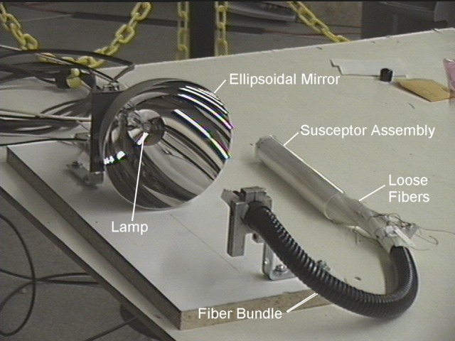
Figure 2. Image of optical heating system assembly, including lamp, elliptical mirror, fiber bundle, quartz holder tube and susceptor.
High temperature quartz fiber optics that have an operating temperature of almost 1100°C were used to transfer the radiant power into the furnace. To obtain an even distribution of the radiant power along the
Table 2. Radiant power loss mechanisms and their efficiencies for the transfer of power from a lamp through fibers to the crystal.
...................................................Efficiency....................Power
Initial Electrical power...................................................150W
Electrical-radiant conversion...............15%.....................22.5W
Solid angle capture...............................40%.....................10W
Fiber optic packing fraction..................80%....................8W
Fresnel surface reflection......................90%.....................7W
Emitted/Absorbed bandwidth...............60%...................4.2
Fiber breakage.........................................95%......................4W
circumference of the susceptor, The output fibers were mixed into 9 smaller bundles such that each bundle had the same output power levels +/- 10% as measured by the radiant power meter. The 9 bundles were distributed in an annulus, and the fiber ends potted into a susceptor molded from opaque high temperature cement (Durabond 952, Cotronics, < 900°C) susceptor. The susceptor and fibers were formed to fit around the ampoule and inside a quartz tube whose end matched that of the susceptor ring.
The susceptor apparatus operating in the furnace is shown in Fig. 3. In this image the glowing susceptor is providing the only illumination within the furnace at 570°C. The liquid surface of the ampoule can be seen at the top of the image. The solid CsCdCl3 crystal surface is seen 2 heater coil widths above the susceptor end.
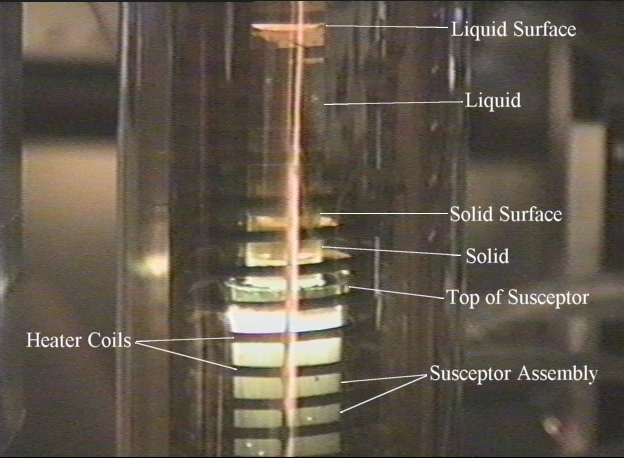
Figure 3. Image of transparent furnace showing heating coils, susceptor assembly surrounding ampoule with liquid and solid CsCdCl3.
4. Crystal growth experiments using auxiliary optical heating
As a first demonstration and motivation for further development of auxiliary optical heating, control of the solid/melt interface shape was judged to be an appropriate goal. This is a well known problem with a known goal - to maintain a slightly convex interface throughout crystal growth [1]. An appropriate heat input to the outside of the ampoule will be able to flatten the profile in the case where the thermal conductivity of the liquid is significantly higher than that of the solid. The flatness of the profile is limited by the effects of heating the ampoule, but the ability to directly deposit heat into the crystal should enhance control of the interface.
4.1. Fiber Optic Power Transfer
Experiments were performed to determine the amount of power that could be transferred to the input of the fiber optic bundle from the 500 W quartz halogen bulb. A flat response, wide band thermopile power meter (Molectron) was positioned such that entire image of the lamp filament focussed by the elliptical mirror was captured on the sensing face. Although the full power measurements were prevented by limitations of the power meter, a factor of 2 extrapolation of the linear experimental data indicated that 27 W (18.5 % power efficiency) was transferred to the bundle face at full lamp power (140 VAC RMS).
4.2. Temperature Profile Modification
Based on the work of Cheng et al [3] two heating zones of the furnace were adjusted to grow CsCdCl3 crystals, using a thermal gradient where the temperature was 620°C at the center of the top heating zone and 480°C at the center of the bottom zone. This led to crystallization in the cooler region and a fixed solid-liquid interface between zones for a fixed ampoule location. Experimental temperature profiles in the furnace are shown in Fig. 4 at a slightly lower average temperature at different radial locations.
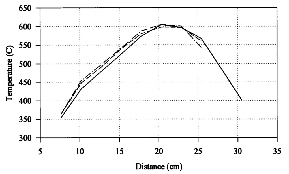
Figure 4. Axial temperature profiles at different radial locations in the furnace, without the ampoule or the fiber optics in place.
Axial and radial variations in the furnace temperature without the ampoule are shown in Fig. 5, with the fiber optic heating in place for a radiant power of 131/4 W. For comparison, a measurement of the furnace axial temperature gradient without the fiber optics is shown for the furnace operating at a lower temperature. There is a significant temperature increase at the vertical location of the susceptor at all radial locations as a result of the auxiliary heating. The furnace gradient with auxiliary heating is similar to that without heating, except that the heat from the susceptor travels down the fibers. This adds heat to the lower furnace zone at the fiber location, but increases the furnace gradient at the end of the lower zone as a result of heat conduction through the fibers passing out of the bottom of the furnace.
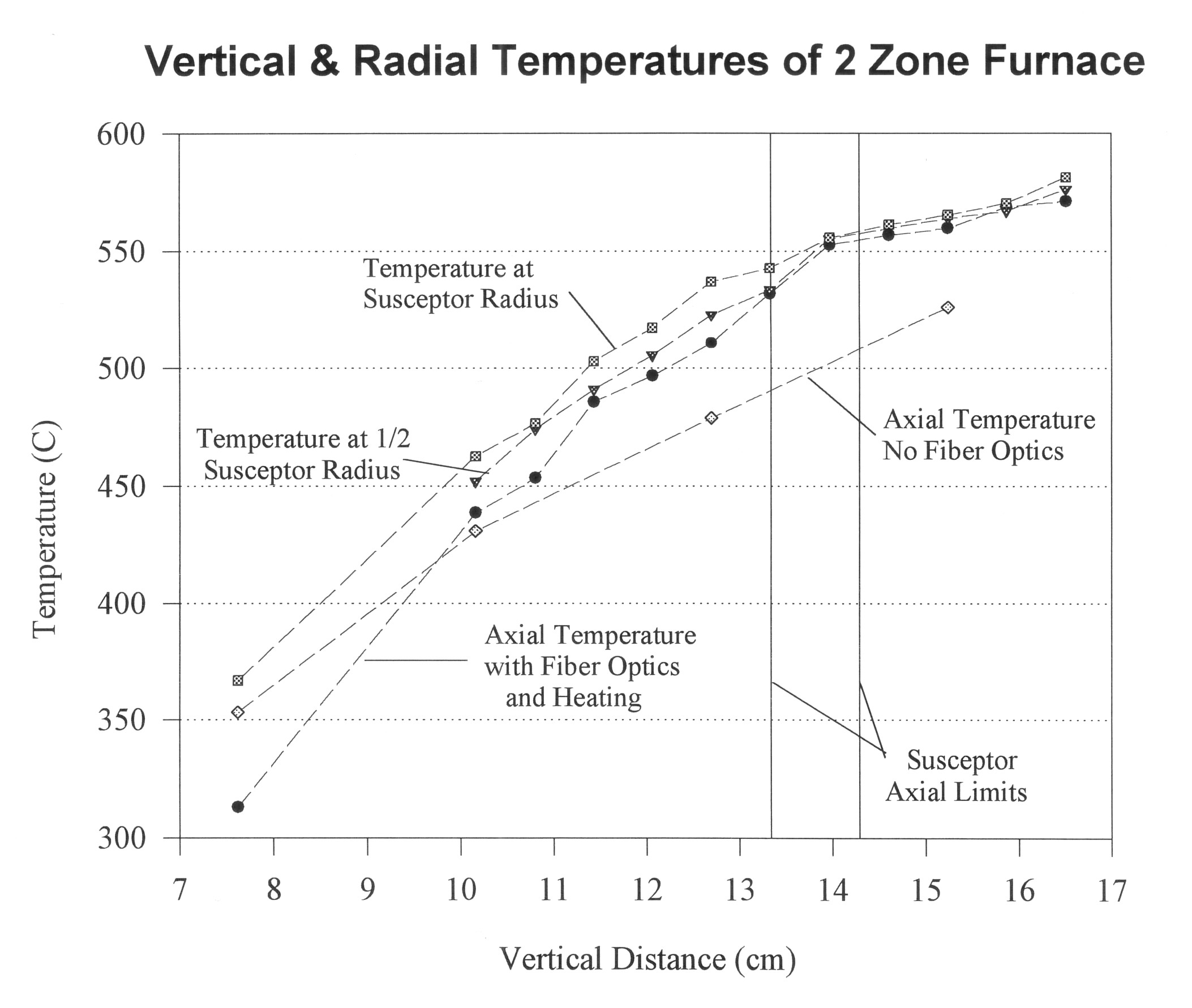
Figure 5. Axial temperature profile of the furnace with lamp at 131/4 W radiant power without ampoule in place.
Varying the auxiliary optical heating in the furnace with the ampoule in place leads to the temperature increases in the furnace shown in Fig. 6. The measuring thermocouple was placed in contact with the quartz ampoule in the upper zone, on the susceptor at the center of the furnace, and between the OD of the susceptor and the ID of the quartz muffle tube. At maximum power optical heating of the susceptor can superimpose a localized increase of approximately 20°C while increasing the temperature away from this zone by less than 6°C.
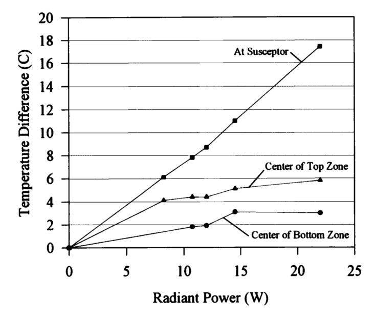
Figure 6. Local furnace temperature dependence on auxiliary heating radiant power.
4.3. Crystal Growth Experiments
The ampoule was first heated at uniform temperature to melt and homogenize the raw CsCdCl3 material in the ampoule. The CsCdCl3 solid melted rapidly at 545°C. Black, inert particles were observed attached to the walls of the ampoule above the liquid surface and floating on the liquid surface, but not in the liquid itself. These are assumed to be oxide contaminants introduced during the sealing of the ampoule that were present at the top of the ampoule before melting. Lowering rates of between 1 cm/hr and 4 cm/hr were used for crystal growth experiments: higher rates did not generate high quality crystals.
Crystal growth experiments were performed to explore the capabilities of the auxiliary heating and to define the details of growing CsCdCl3 under the conditions existing in the transparent furnace. Interface and internal defects were readily visible as a result of the light scattering from the defects or the crystal facets at the surface of the solid. Convection patterns in the liquid were identified through the motion of crystallites suspended in the liquid. Scattered HeNe Laser light was also used for illuminating the melt/solid interface of the transparent crystals.
An image of a crystal interface in the presence of the simple thermal gradient given above is shown in Fig. 7. The solid interface can be seen much more clearly than it can be imaged. This is an 8x magnified image taken by a standard NTSC COHU monochrome camera. The surface of this crystal was concave, had a high reflectivity, and was quite uneven. The CsCdCl3 crystal, unlike the yellow-brown liquid, was colorless. The image shows two of the heating coils and a vertical coil positioning support. The image was backlit by a quartz halogen bulb placed several inches above the solid surface on the other side of the furnace from the camera. The vertical white bars that partially obscure the coils and crystal are reflections of the light source by outer quartz cylinders of the furnace. A consistently concave surface forms at the same axial location in the furnace when the ampoule is lowered. Cheng et al [3] report a convex solidification surface rather than the concave surface observed here. This difference was attributed to differences in axial thermal gradients in the two furnaces.
4.4. Interface Shape Control
Applying the auxiliary heating to the furnace temperature profile led to the formation of convex solid interface shapes in the ampoule. Concave, flat, or convex surfaces could be achieved by changing the auxiliary heating. Figure 8 shows a 4x magnification of a typical crystal produced when the solidification interface formed below the top of the susceptor. In this case, the top of the susceptor was 9.2 cm above the bottom of the furnace and a convex solid surface formed 6.4 mm below the top of the susceptor. The crystal was raised manually above the top of the susceptor so that a clear image could be taken. The camera is looking down onto the crystal surface from a 20° angle from the plane of the interface, and the crystal is lit only by the illumination from the fiber optics. The convexity of the crystal is clearly visible, as is the clarity of the carefully grown crystal at the top of the solid. The lower, less perfect portions of the solid were formed during experiments that varied the height of the susceptor and lamp power.
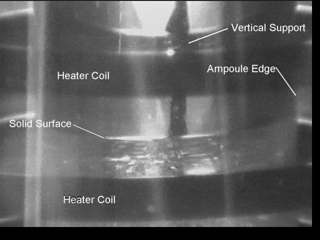
Figure 7. Image (8x) of typical CsCdCl3 crystal with concave interface; no auxiliary heating.
It was also possible to create a convex surfaced crystal with the top of the susceptor below the meniscus of the solid. This required the susceptor to be lower in the furnace than with the case of the solid forming below the top of the susceptor discussed in the above section. The radiant power and the susceptor height were adjusted incrementally until a convex surface was observed to be stable without translation of the ampoule at a radiant power of 81/4 W. The lamp power was at 45 percent of 120 VAC RMS. The crystal surface formed 2 mm above the top of the susceptor at 131/4 W radiant power. Increasing the radiant power from the lamp for a fixed position of the susceptor caused the surface to form closer to the susceptor. When the susceptor was too low in the furnace or below approximately 103/4 W radiant power concave surfaces were formed. Surfaces formed with this technique were flatter than those formed below the top of the susceptor. These convex surfaces could be formed with the susceptor top between 8.5 and 10.1 cm above the bottom of the furnace.
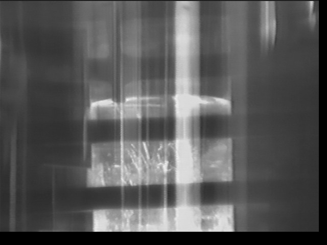
Figure 8. Image (4x) of typical CsCdCl3 crystal with convex interface using 12 W auxiliary heating power.
5. Conclusions
Auxiliary optical heating near the solidification zone during crystal growth from a melt has been demonstrated to be able to control the liquid/solid interface shape. Concave, flat, or convex surfaces could be achieved by changing the auxiliary heating. Radiant heat was collected from a standard halogen lamp by an elliptical mirror and transferred through fiber optics to a movable absorber/heater ring (susceptor) next to a crystallization ampoule in a crystallization furnace. The long-term variation of the delivered power was found to be compatible with crystal growth. The results indicate that the heating uniformity, localization, and controllability appropriate to improved crystal growth are achievable using this technique.
The primary technical benefit of auxiliary optical heating is to provide a mechanism for fine control of the local heat transfer to a growing crystal.
Acknowledgements
The author gratefully acknowledges the support of this work by the National Aeronautics and Space Administration, Marshall Space Flight Center, under Contract # NAS8-40546, and the consulting advice of Prof. R.S. Feigelson of Stanford University.
References
[1] G.C. Cheng, D. Elwell, R.S. Feigelson, and C.E.Huang, J. Crystal Growth, 73, (1985) 417.
[2] K.S. Hahn, R.A. Carranza, D. Elwell and R.S. Feigelson, J. Crystal Growth, 50, (1980) 775.
[3] T. Jasinski and A.F. Witt, J. Crystal Growth, 71, (1985) 295.