A Small Coal Ash Generator Used For Acoustic Agglomeration
S. C. Bates*, Gerhard Reethof**, Wayne Smith**
* Thoughtventions Unlimited, 40 Nutmeg Lane, Glastonbury, CT 06033
** Retired
*** Advanced Fuel Research 87 Church St. East Hartford, CT 06108
ABSTRACT
The development of a small, inexpensive source of a realistic ash-laden hot gas stream and its use to test acoustic particle agglomeration is described. A small coal-particle flame flowing through an electrically heated tube supplies a controllable, high-temperature, ash or char particle laden combustion product exhaust that can be used to test hot gas cleanup techniques. Particle loadings comparable with current power combustion/gasifier system exhausts were achieved; lignite and bituminous coal types were used for testing. Lignite ash exhaust was used to test acoustic agglomeration of coal ash particles. Significant acoustic agglomeration of combustion-generated coal ash particles has been accomplished, measured in detail, and is in reasonable agreement with modeling.
KEYWORDS: Acoustic, Agglomeration, Hot, Gas, Cleanup, Coal, Particle, Ash
INTRODUCTION
The combustion of coal in gasifiers and combustors produces particle laden hot gas streams that are used to supply a wide variety of energy conversion devices. A higher temperature exhaust improves the thermal efficiency of energy extraction but also greatly exacerbates the erosion and corrosion caused by the particles in the flow. Another problem caused by particles in the flow is fouling of turbines or fuel cells that results in a significant degradation in system performance. The possibility of fouling has resulted in a flow specification that limits the overall mass loading of particles per unit volume. Furthermore, the finest particles are also emitted into the atmosphere and are known to cause lung disease. A hot, particle-laden exhaust is such an extreme environment that severe constraints are placed on the materials and processes used in devices that can be used to remove these particles; devices that are practical are also expensive and require a great deal of maintenance.
Particulate control requirements for turbine systems are guided by the turbine industry. Although there is no consensus among all turbine manufacturers, it is agreed that very low concentrations of particles are necessary and that no particles should be larger than about 5 to 12 µ m. Control of the smaller particles is not as important as control of the large particles, because particles that are smaller than about 5 µ m stay in the flow stream and do not strike the turbine blades. A particulate loading of 0.01 gr/scf (0.023 g/m3) for particles that are less than about 5 µ m is believed to provide adequate turbine protection and is sufficient to meet current emission regulations for particulate matter emitted from coal-fired boilers.
Particle removal is usually evaluated on a relative mass basis (i.e. the percentage of the total particulate mass). These measurements are estimates because total emissions can at present only be measured using fine filtering of sample gases, whereas the actual particle mass is time varying and dependent on many combustor parameters. The size distribution of the particles is also important. While most of the particle mass is usually contained in the larger particles, there are numerically more smaller particles that are important to remove because of their danger to human health or equipment.
Acoustic agglomeration is a method used for aerosol conditioning that improves particulate removal in combination with conventional techniques. High intensity acoustic fields applied to the hot gas stream have been shown in laboratory scale work on dust particles to predictably agglomerate micron-sized particles into larger particles and dramatically reduce the concentration of both submicron and micron sized particles.
APPARATUS
A diagram of the hot gas exhaust generator and acoustic agglomerator is shown in Fig. 1. The gas generator apparatus consists of an entrained-flow coal feeder, a coal burner, and an electrically heated section to achieve a controllable exhaust temperature. The exhaust then passes into an electrically heated acoustic agglomerator section.
The goal of the gas generator apparatus was to generate a gas/particle flow that is a realistic representation of a modern coal combustor exhaust. This type of exhaust is characterized by a high temperature, a particle mass loading, a particle size distribution, and a type of particle that depends on the coal feed used and the combustor design and operating conditions.
The design of the exhaust simulator was dominated by 1) the need for a fairly high particle loading in a high temperature flow, 2) the requirement that the particles be combustion generated, and 3) the requirement that the overall facility be relatively small, simple, and inexpensive. The exhaust simulator concept described here was made possible by the combination of a small-particle coal feeder to supply fuel to a coal particle flame, and an electrically heated tube to heat the resulting particle-laden flow to a temperature that is characteristic of a full-sized coal combustor driving a turbine. The condition and mass loading of the coal combustion particles can be controlled not only by controlling the particle feed rate, but by varying the oxygen content and/or dilution content of the gas stream.
The Coal Feeder
An entrained-flow coal feeder first developed at MIT was used to supply coal particles [1]. The coal feeder consists of a sealed vertical coal reservoir with an inert gas supply at the top, a central, motor-driven, small diameter (1.3 mm inner diameter) feeder tube that moves downward with the coal surface, and a vibrator to aid the sliding particle movement into the tube. Mass feed rates using one coal feeder can be adjusted from 0 to 1.5 g/min.
This feeding system was further developed to be able to feed very fine coal dust (particle diameter<45 microns). A steady mass rate of coal particles into the feeder entrainment gas is necessary for the proper function of the combustor. Using fine dust, the standard arrangement of the feeder system resulted in an unsteady coal feed and a very non-steady flame. Inspection showed that clumps of coal were being sucked into the feeder. Vacuum drying the coal did not improve feed uniformity and tests of the coal showed that the clumps were actually fairly fragile. A significant increase in vertical vibration energy flattened the surface of the coal reservoir and prevented the agglomeration of the fine particles. This was achieved by attaching a vibrator to the bottom surface of the reservoir and making all of the connections hard - removing soft joints that had been included for sealing purposes. These changes led to satisfactory performance of the feeder when using the fine dust.
The Combustor System
Combustion occurred inside a Mullite ceramic tube (0.95 cm ID x 45.7 cm long) that was heated externally by a commercial ceramic jacket with embedded electric coils. Preheated oxidizer gas was fed into the combustor through a tube immediately adjacent to the entrained coal flow tube. As oxygen/nitrogen and nitrogen-entrained coal dust entered the heated combustion tube the mixture temperatures rapidly rose above 750°C where devolatilization of the coal occurred and the mixed oxygen and combustible gases spontaneously ignited. This type of coal heating and combustion was chosen to achieve certain and complete char burnout. Normally turbulent combustion would result in locally non-uniform heating and combustion and incomplete burn-out, but because the devolatilization of the coal in this case does not depend on combustion heat, burnout is completed everywhere in the flow. Combustion completeness was also enhanced by increasing the oxygen content of the oxidizer, which increased the combustion temperature and decreased the nitrogen dilution of the ash particle density. The entrained coal dust was completely combusted in the ceramic section, and ash particles that were produced by this combustion process were carried downstream to the acoustic agglomeration chamber.
The combustor was enclosed in a 7.6 cm ID schedule 40 steel pipe, lined with 1.27 cm thick porous ceramic material for thermal and acoustic insulation. The combustion flame was protected from the high intensity sound by imposing constrictions and expansions between the sound source and the coal flame. Sound intensity was also reduced by the porous ceramic liner inside the combustion section. A temperature profile in the combustor using pure nitrogen is presented as Fig. 2. Within the first 13 cm gases (and coal) that enter the ceramic furnace are rapidly heated to 800°C. Near this point devolatilization and ignition occur.
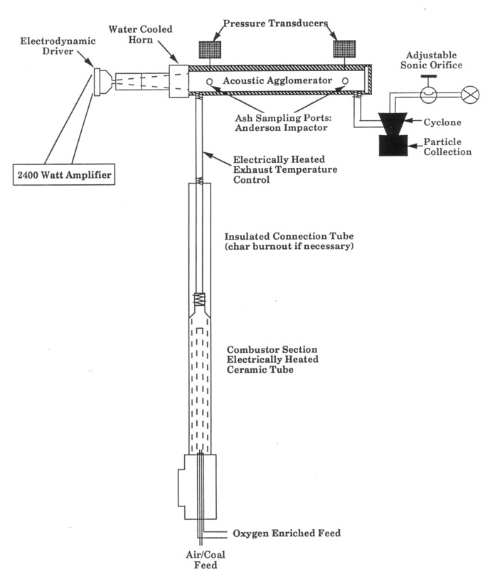
Figure 1. Drawing of a hot gas stream generator and acoustic agglomerator facility.
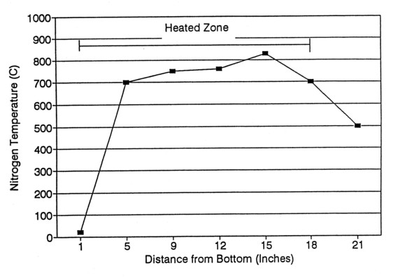
Figure 2. Centerline temperature profile in the coal combustor.
Various coal types were used in the combustion tube. Operating conditions of temperature, flow rate, and oxygen percentage for combustion were established. The temperature of spontaneous combustion varied for different coals and was dependent on coal rank. For example, lignites were shown to combust at lower temperatures of 750°C, while bituminous coals required higher temperatures of at least 800°C to combust. At temperatures between 900-1000°C all coals were shown to combust completely.
Exhaust Temperature Control
The ash-laden gas emitted from the combustor passed through a 2.5 cm 40 inconel pipe wrapped with a thin layer of high temperature kanthal wire and thick external insulation. Heating the wire provided variable exhaust stream temperatures up to 900°C. The axial temperature profile is controlled by varying the thickness of the insulation along the length of the tube.
Hot Exhaust Gas Simulator Parameters
Overall particle loading was controlled by the parameters of the coal feed system and the gas feed rate. An entrained-flow coal feeder (three can be used in parallel) supplies about 1 g/min of coal, in 5 l/min of flow. If the coal combustion results in 20% ash, these feeders would supply about 0.2 g/min of ash particles. An air/fuel mass ratio of approximately 15 is needed to completely burn the coal. Assuming air is used as the oxidizer (ρ air ≈ 1 g/l), 15 l/min of air is required. At 900°C this implies an air volume of 60 l/min and an ash mass loading of 3.3x10⁻³ g/l or 3.3 g/m3. This is a relevant mass loading for acoustic agglomeration in power systems, which typically varies from 1-10 g/m3. Acoustic agglomeration will not work for mass loadings below 0.1 g/m3 as a result of the large interparticle distance compared with the particle motion driven by the sound waves. Ash particle in mass loading can be increased by decreasing the nitrogen fraction in the oxidizer, and consequently the overall volume flow rate for a given coal feed rate.
Acoustic Agglomerator Section
The acoustic agglomerator section had three components: the acoustic driver, the horn, and the agglomeration chamber. The agglomeration chamber was a 7.6 cm schedule 40 inconel 600 pipe 1.0 m long. The inconel pipe provided a high temperature acoustically reflective surface for optimum transmission of the sound. The pipe surface was coated with ceramic paste, for electrical insulation and heated electrically on this outside surface using Kanthal wire. The agglomeration chamber could be heated to above 1000°C when thermally insulated. The acoustic horn was made in three sections (2 aluminum sections near the horn and 1 stainless steel type 304 section next to the hot inconel pipe). Each horn section had a linear slope but the total horn area expansion was approximated exponential. The throat of the horn had an ID of 3.8 cm and a mouth ID of 7.6 cm. The total length of the horn was 34.3 cm with a flare constant of 0.038 cm-1. The stainless steel horn section was water cooled to prevent heat transfer to the rest of the horn from the adjacent high temperature pipe and flows. The electrodynamic driver was water cooled to prevent heat damage from the high electrical power dissipation. Externally insulated inconel was used for the agglomeration chamber where no internal thermal insulation is permitted because of its sound absorbing properties.
The gas velocity in the AA was about 25 cm/s at 900°C so that a pipe length of 1.0 m gave a 4 s residence time for full effectiveness of the acoustic agglomeration. An acoustic power of about 180 acoustic watts was needed to achieve a sound level of about 160 dB in the 7.6 cm diameter pipe. Losses associated with the coupling to the pipe forced the sound driver to provide about 600 acoustic watts. For this system an electrodynamic driver coupled to a high power commercial audio amplifier was adequately mounted with carefully designed acoustic couplers. The acoustic agglomerator was instrumented to measure the sound intensity just downstream of the flow entrance and at the end of AA section. Access for particle sampling with an Anderson Impactor was included at these locations also.
Diagnostics
The primary facility diagnostics were: 1) thermocouples and rotameters to measure gas temperatures and gas flow parameters, 2) a pressure transducer to measure sound intensity levels, 3) an Anderson Impactor and fine pore filters to measure particle size distribution and particle loading, and 4) fine pore filters to measure particle loading.
Thermocouples (type K) were placed around the combustor, at the exit of the heated tube reactor, at the entrance of the agglomerator, along the agglomerator tube wall, and inside the agglomerator tube at the entrance and exit. The various sections of the apparatus were all heated electrically. Separate variacs provide independent temperature control of the combustor and the 3 sections of the AA pipe. Heating tapes were used for additional heating of specific parts of the apparatus to prevent condensation of the water vapor generated by combustion. Rotameter flow meters measured the primary, secondary, and coal feeder gas flow rates.
A miniature water cooled pressure transducer (PCB Piezotronics, Depew, NY, model #112A22), designed for high intensity acoustic measurements was used to sense low pressure sound with high resolution and acceleration compensation. This transducer has a 0.7 MPa range and a 7 Pa resolution with a 250 kHz resonant frequency. An oscilloscope simultaneously measured the frequency and the acoustic pressure amplitude output.
Anderson Mark III Particle Sizing Sampler - The Anderson Cascade Impactor is a sampling, multi-stage cascade impactor which measures the size distribution of particles in the sampled gas stream in addition to total particulate mass concentration. Stainless steel substrates are used to be compatible with the high gas temperatures. The Anderson Stack Sampler is calibrated with unit density (1 g/cm3) spherical particles, and measures the aerodynamic particle size. The connection between aerodynamic particle size and true particle diameter is a complicated function of particle shape and density. The range of particle sizes collected on each stage are always identical for any given sampling conditions. All impactor data presented in this work are given in terms of aerodynamic diameter; no corrections have been made for variations in particle density.
Elevated temperatures affect the gas viscosity and the Cunningham slip correction factor, thus affecting the impactor particle sizing characteristics. To obtain the most accurate results that take into account changes in gas velocity, viscosity, temperature, pressure, Cunningham slip factor and particle density, a commercial computer program for cascade impactor data reduction [2] was used.
Particle Filters - To gain a more precise determination of the overall particulate mass loading, fine pore particle filters were used for collection. These were Teflon coated paper particle filters mounted in a sealed stainless steel holder. A pore size of 0.5 mm was used as the best compromise between particle collection and pressure drop. Although this filter does not trap the smallest particles, it traps all of the particles responsible for the mass loading; for a mean particle size of 5 mm with a lognormal distribution, negligible mass was lost through the filter.
PROCEDURES
The Coal Feed
The hot gas generator was tested with Illinois #6 bituminous coal and with a Texas Lignite (Titus - Penn. State Coal Bank PSOC 416). One coal feeder was used to feed sieved -325 mesh coal to achieve a fine ash particle loading in the gas stream. The small initial particle size was designed to enable high mass loadings by entraining into the flow all of the ash in the coal and to ensure 100% combustion. Large coal particles may not have a residence time long enough to completely combust. At the start of an experiment the top of the feeder tube is level with the coal bed and the tube is immersed in the coal particles. The desired entrainment flow rate is turned on before an experiment, entering from the top of the feeder. When the experiment begins, the feeder tube end moves downward below the level of the coal bed at a steady rate. During the feeding process vibrational energy is supplied to the entire chamber to maintain a loose and easily flowing surface, so that the flow entrains the coal as the feeder tube moves downward into the bed.
Particle Measurement
Particle Size Distribution The Anderson Impactor sampled ash at the entrance and the exit to the AA. A 3/8" type 304 stainless steel probe was specially designed and used for ash collection from the hot flow into the Anderson Impactor. A vacuum pump and a metering orifice controlled the sampling flow rate through the Impactor. Sampling gas flow rates were measured with a calibrated rotameter and corrections were made for pressure differences. The flow rate is the most significant factor determining the particle sizing collected on each stage of the Impactor. The cascade impactor was heated by a heating tape to eliminate the condensation of water that might affect the collection of ash particles. The orientation of the Cascade Impactor is not important while sampling. After sampling, the Impactor was held vertically and handled carefully so that the fragile agglomerates in the sample would not be disturbed before weighing. Two to three measurements were made at each test condition to assure repeatability.
The lowest recommended sampling flow rate that can be used in the Impactor is 0.1 acfm (2.8 l/min). At flow rates lower than this the stages will not separate particles effectively, and the particle size distribution range on each stage becomes larger. As the particle size distribution becomes broader the size resolution of each stage decreases because there are a maximum of 10 stages to collect ash particles. For stage #1 particle sizes range from 18.7 microns to 6.8 microns as the flow rate varies from 0.1 to 0.75 acfm in air at 70°F. The resolution for a sampling flow rate of 0.1 acfm is approximately +/- 6.5 microns and +/- 2.3 microns for a flow rate of 0.75. An optimum sampling flow rate is about 0.5 acfm, which is not usually consistent with performing isokinetic sampling as is recommended. Isokinetic sampling requires that the sampling velocity through the sample probe tip be equal to the velocity in the stack. There are two ways to match sampling with flow velocities for isokinetic sampling: to adjust the sampling flow rate through the probe, or to adjust the diameter of the sampling probe.
Particle Mass Loading Measurements of the particle mass loadings were made by isokinetically drawing aerosol samples from the agglomerator exit and the cyclone exit passing the flow through a multipore filter for a predetermined time, weighing the mass on the filter. Fast acting solenoid valves were used to control the collection time. Assessments of agglomeration and particle size distribution changes were made by collecting particles on a filter and examining them using microscopy (optical and Scanning Electron Microscopy).
Char Burnout
Effluent from the combustor was collected and particulate matter (ash, char and unburned coal) was analyzed to determine the amount of uncombusted material. Samples were analyzed using a TGA. The weight loss was calculated after the water has been driven off the sample. Burnout percentages of 98% were achieved with this combustor.
Acoustic Agglomerator
The coal combustion system generated a hot aerosol that entered the acoustic agglomerator and was subjected to sound levels in the 150 dB range. The current carrying limitations of the electrodynamic driver required us to operate the acoustic agglomerator at one of its resonant frequencies, which was close to 590 Hz. The exact resonant condition depends on the gas temperature since the speed of sound is proportional to the square root of the absolute temperature. The wavelength in turn is given by the ratio of speed of sound to frequency. For the end conditions of the AA, the frequency of 590 Hz corresponds to approximately one wavelength in the 2.8 ft long AA. By adjusting the driving frequency to obtain the maximum sound pressure level both inside and outside the AA the electrodynamic driver could be operated for long periods of time. The driver coil was burned out by running at too high intensities during preliminary runs (4 min. at 160 dB). The sound driver also limited operation at frequencies below 1000 Hz as a result of decreasing frequency response above that frequency.
The optimum acoustic agglomeration frequency depends on the particle size distribution, both in terms of the mean particle size and the size variability as described by the standard deviation in particle size. In addition such factors as gas temperature, gas pressure, gas composition, and particle density and shape affect the optimum frequency. For the present case of particles with a density of 2,360 kg/m3 a mean size of about 2.5 microns (a geometric mean of about 3.5) the optimum frequency is near 2000 Hz, based on agglomeration simulation results. The particle size distribution was determined by the coal particle size being fed to the combustor and the burning characteristics of the coal as well as its surface characteristics. Particle geometry and particle surface characteristics vary for different coal types, which in turn affect the AA process.
Sound Levels
Independent sound measurements were performed with a calibrated sound level meter to confirm the accuracy of the pressure transducer. Measurements were taken inside the acoustic agglomeration chamber at two frequencies, 908 and 776 Hz, agreeing to within 4%. Measurements were also taken with the calibrated sound level meter to determine the amount of noise released into the laboratory. These measurements are required by OSHA to ensure that noise levels are within specified safety limits. Most of the noise was caused by transmission through the schedule 40 pipe and heating insulation in the agglomeration facility and was partially absorbed by acoustically insulating tiles lining the room. The highest measured sound level recorded outside was 85 dB.
Independent tests of sound intensity in the AA were performed, and acoustic levels of 165 dB were obtained for short periods. Agglomeration tests with coal ash were conducted at sound levels of 150 dB for approximately five minutes. Despite water cooling, the driver coil burned out after 10 minutes at 165 dB. The driver was repaired and used at 150 dB for the final successful testing.
EXHAUST GENERATOR RESULTS
The exhaust generator produced particle-laden gas at temperatures up to 950°C with over 98% char burnout. The combustion was almost too effective, because SEM inspection of the char particles showed them to be spherical, which meant that the ash was fully molten at some point in the combustion process. This is not the case for many coal combustors; the non-spherical shape of the ash particles is a significant factor in particle collection techniques. The exhaust gas generator was operated with minimum nitrogen to maximize ash loading, which meant that pure oxygen was added to the nitrogen that was used to entrain and carry the coal particles to the combustor. This enhanced oxygen fraction in the combustion gas increased the flame temperature and the combustion temperature in general, causing the particle melting. Lowering the combustion temperature would be desirable for creating more representative ash particles, but it also would have lowered the ash mass loading in this particular device, greatly decreasing acoustic agglomeration effectiveness. In this device a lowered combustion temperature could only be achieved by diluting the oxidizer flow and increasing the gas flow relative to coal flow.
Particle loading measurements were initially performed using the sampling probe and a 0.2 micron filter and confirmed later using a 0.5 micron filter that had a much lower pressure drop and much shorter collection time as a result of higher allowable flow rates at a given pressure drop. A total mass loading at the exit of the combustor was measured to be 5.5 g/m3 at 600°C, for a sampling flow velocity of 250 cm/sec. The combustion gas velocity was estimated to be 40 cm/sec, so the measured mass loading was actually somewhat higher because all of the largest particles were not captured.
The overall limit on the flow rate of the ash generator (aside from cost) results from limits on the coal mass feed rate of the feeders (1 was used; up to 3 can be used), and the electrical heating demand of larger tubes. The feeders are limited to a few g/s because larger sizes lead to non-uniform flow loading.
ACOUSTIC AGGLOMERATION SIMULATIONS AND EXPERIMENTAL RESULTS
Acoustic agglomeration (AA) is an intermediate treatment of particle-laden aerosols in clean-up trains to improve the performance of conventional particle removal devices. Exposing such particle laden aerosols containing micron and submicron sized particles to high sound levels in the range of 150-165 dB at the correct frequencies (500-3000 Hz) and for sufficiently long residence times (3-5 seconds) results in much increased rates of particle collisions, adhesions and thus agglomeration. Particle size increases by a factor of 5 or more have been observed. Such increased particle sizes substantially improves the fractional efficiency of conventional particle removal devices such as cyclones, scrubbers, baghouses, granular bed filters, and electrostatic precipitators.
Much research has been done on Acoustic Agglomeration in this country and abroad for almost 100 years. Of particular interest is the work at the Pennsylvania State University under the direction of Dr. Gerhard Reethof and Dr. Gary Koopman [3-8], the State University of New York at Buffalo under Dr. David Shaw [9-13], and the University of Toronto in Canada [14-16] over the last 15 years. The Penn State work has provided a much better understanding of the fundamental issues underlying acoustic agglomeration and has demonstrated on small scale AA laboratory test rigs with reentrained, processed dust that AA is a technically and economically viable approach. Work has also been done in Russia [17-19], Germany [20-23], France [24-26] and Spain [27-28]. The results of this research, particularly the work at Penn State, clearly prove that AA provides significant and predictable particle growth and that the resulting agglomerates are robust [5].
Computer Simulation
An Acoustic Agglomeration Simulation Model (AASMPC) was developed by Dr. G. Reethof at Penn State University's High Intensity Acoustics Laboratory. The simulation model [31] incorporates the key physical mechanisms of AA, which are: 1) particle entrainment due to viscous and boundary layer phenomena; 2) wave scattering; 3) hydrokinetic interaction between particles; 4) Orthokinetic interaction, which is the effect of large particles sweeping out volumes as small oscillating particles collide with the large convecting particles; and 5) acoustic agglomeration rate processes and the dynamics of particle size distribution in space and time.
The major forcing characteristic of AA is the acoustic flow velocity, Uac, which in turn is generated by the acoustic pressure field. If it is assumed that there is a plane wave travelling in the AA, the acoustic velocity Uac is given by:
Uac = Pac/ρ c
where Pac is the acoustic pressure, ρ is the density of the medium, and c is the speed of sound in the medium. The speed of sound is:
c = (kRT)1/2
where k is the ratio of specific heats, R is the gas constant for the medium, and T is the absolute temperature of the medium. The acoustic impedance is given by:
ρ c = P(k/RT)1/2
The properties of the gas are contained in the gas constant R and the ratio of the specific heats k. Settling is important in a horizontal AA since large particles tend to fall to the bottom and change the particle size distribution as the aerosol is convected through the agglomeration process. The settling effect has also been included in the AA Simulation program.
Hydrodynamic particle-particle interactions dominate the AA process. The large particles that are only partially entrained in the acoustic velocity flows are convected downstream by the average motion of the flow while small particles which are fully entrained oscillate, collide with, and stick to the surfaces of these larger particles, emptying out what may be called agglomeration volumes around the larger particles. Another important hydrodynamic effect is the flow between two particles that are separated by a distance of the same order of magnitude as the particle sizes. In this case, for partially entrained particles, the high velocity flows between the particles results in pressure distributions that force the particles toward each other and cause collisions. It is assumed that Brownian effects, interparticle drifting effects and gravitational flows result in complete fill-up of these agglomeration volumes before the AA process begins.
At the high acoustic intensities that are required, in the vicinity of 160 dB, nonlinear acoustic effects can become important and will influence the AA process. Downstream from the sound driver and within the confines of the AA chamber there are some acoustic streaming effects. This phenomenon results in very low velocity recirculating flows. Of probably greater importance are the Wave Steepening effects which become progressively more pronounced with each passing wavelength. The large acoustic pressure fluctuations actually result in increases (and decreases) in sound speed at the peak (or trough) of the wave until acoustic shock waves are produced similar to the wave breakers in the ocean.
The simulation model assumes that the particles are spherical and that all collisions result in adhesions, an assumption that will be tested together with other assumptions. Another important consideration is the actual (effective) density of the forming agglomerates. If spherical particulates are assumed the empty volumes between the adhering particles will decrease the effective density of the increasingly larger agglomerates. This fact is considered in the model by assuming that particle density of the agglomerates decreases with their size.
In order to simulate the test conditions in the AA system the particle size distribution in the acoustic agglomerator as measured by the Anderson Mark III impactor with no sound was reproduced. The simulation then generates the mass distribution in 45 bins over a range of 0.01 to 25 micron particles. A particle density of 2,360 kg/m3 was chosen on the assumption that most of the particles were silica and alumina. Program inputs are the agglomerator size, the gas temperature, the gas pressure, which are used to calculate the pertinent acoustic parameters. A residence time of 7.2 seconds, was used, together with an acoustic level of 150 dB, a frequency of 583 Hz, a temperature of 233°C, and a particle mass loading of 1.6 g/m3. The program calculated an acoustic velocity of 2.87 m/s. The initial number of particles per unit mass were reported as 0.1237 x l014, the initial geometric mean diameter was reported as 3.56 microns for the nonparametric distributions.
The simulation predicted an increase by a factor of 4.0 in the geometric mean diameter to 14.2 microns of the resulting particle size distribution due to AA. The particle size distribution data before and after AA is presented graphically in Fig. 3, compared with experimental results. The agreement is good at the lower particle sizes, but less so at the larger particle sizes. The agreement is good enough to further confirm the validity of the many assumptions that had to be made to arrive at a practical simulation code.
Acoustic Agglomeration Experimental Results
Agglomeration was tested using a variety of coals, ash mass loadings, residence times, and acoustic intensities. Agglomerator performance was measured using acoustic sensors to test the acoustic driving force, particle filters to measure particle loading, and an Anderson Impactor to measure particle size distributions.
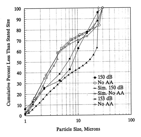
Figure 3. Cumulative particle size distribution for Acoustic Agglomeration, no acoustic driving, and simulation results.
Particle residence times of 4 s and longer were achieved in the region of acoustic agglomeration. Using a single electrodynamic driver sound levels up to 160 dB were achieved for short periods of time, 150 dB was maintained for 4 minutes, and 145 dB could be maintained for 20 minutes. Illinois #6 and a Texas lignite coal were tested for acoustic agglomeration of the resulting ash. Detailed agglomeration testing was performed with the lignite coal because of its high ash content and lower combustion temperature.
Acoustic agglomeration results for Texas lignite ash are shown in Figs. 3 and 4. Figure 3 shows two repeat runs with no sound, two runs with approximately 150 db sound intensity, and simulation results for these conditions. Figure 4 shows the detailed weighings from the individual impactor stages that go into making up the data. The available data was limited by acoustic driver problems and the six month project duration.
The acoustic agglomeration process has in effect removed the smaller particles by agglomerating them to larger size agglomerates, which now appear in the larger particle size regions. For a residence time
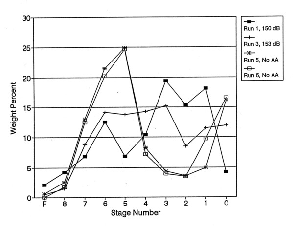
Figure 4. Ash weight percent collected on each impactor stage with and without acoustic driving.
of 7 sec, a mass loading of 2 g/m3 at 260°C, a sound level of 150 dB, significant agglomeration was demonstrated; the number of particles less than 5 µ m in diameter decreased from 62% to 40%. In the 50 percentile range the particle size has increased from the original 3.5 microns to about 8 microns. Thus acoustic agglomeration has performed its function of providing sufficiently robust agglomerates which can certainly withstand the rigors of passing through the high velocity regions of the inertial separation processes in the impactor.
The mass loading of the aerosol has a very strong effect on acoustic agglomeration; thus the higher the loading the more effective will be the AA process since the mean spacing between particles will be closer, increasing the collision probabilities. A detailed discussion of the particle measurements is given because of the importance of the details of the results, and the difficulty of making measurements.
Particle size distribution measurements with the Anderson Mark III impactor are shown to have good reproducibility in Figs. 3 and 4. Great care was taken with the preparation of the plates and substrates and the handling during weighing with 4 place precision scale (Mettler Model HK160). Since there is a substantial amount of moisture in the combustion gases the impactor was heated to keep its temperature above the condensation temperature for water. The particle size distributions measurements show better reproducibility for the cases without AA primarily because combustion conditions do vary to some extent between experiments.
An important note is that impactor sampling was not isokinetic. Flow velocities in the agglomerator tube were in the range of 10-15 cm/sec, while the impactor flow velocities were calculated to be almost 3 m/sec. This was a conscious decision to obtain more reliable impactor data, but resulted in a loss of some of the larger particles during sampling. This may account for the differences in the actual particle distribution resulting from the agglomeration and that predicted by the simulation. The absolute flow velocities are low and the ash particles are all small, however, so not many of the particles may have been lost. A lower temperature (233°C) for the flow was used to increase the particle loading and resultant agglomeration effect.
Particle loading measurements were made without agglomeration at the end of the agglomeration chamber using both the Impactor and the particle filter. The flow and temperature were adjusted to maximize residence time and particle loading. Flow velocities in the agglomeration chamber were 10-15 cm/s at a temperature of about 260°C. A higher temperature would be more representative of true exhausts, but would have significantly decreased the mass loading for agglomeration tests. Using a 0.5 micron particle filter, mass loading measured at approximately isokinetic conditions gave a value around 5.5 g/m3 with an error of plus or minus 1g/m3 as a result of the low particle flow rates. Using the same sampling velocities as the impactor the total mass loading measured ranged from 2-3 g/m3, while the total from the impactor stages indicated around 2 g/m3.
The measured mass loading of about 2 g/m3 is rather low for agglomeration. The acoustic agglomerator in the present experiments is horizontal. There is therefore a question whether gravitational settling in the agglomerator does affect the result since the residence times of 7 seconds or more result in a very low axial velocity in the 3 foot long agglomerator. The inside of the AA was inspected several times after long runs and very little dust was found on the bottom of the pipe. Past experience has shown that the high sound levels cause thin walls to vibrate somewhat causing the particles to be re-entrained in the flow.
Scanning electron microscope images of the collected ash particles were taken, however frequent examples of agglomeration were not observed.
CONCLUSIONS
An atmospheric pressure particle laden hot gas generator was designed, constructed and its performance was measured. Exhaust temperatures up to 950°C and ash particle loadings up to 5 g/m3 were documented. Over 98% char burnout was achieved. An acoustic agglomerator was constructed and instrumented using the particle-loaded hot gas from the exhaust generator. Agglomeration was tested using a variety of coals, ash mass loadings, residence times, and acoustic intensities. Agglomerator performance was measured using acoustic sensors to test the acoustic driving force, particle filters to measure particle loading, and an Anderson Mark III Impactor to measure particle size distributions. Particle residence times of 4 s and longer were achieved in the region of acoustic agglomeration. Using a single electrodynamic driver sound levels up to 160 dB were achieved for short periods of time, 150 dB was maintained for 4 minutes, and 145 dB could be maintained for 20 minutes. Illinois #6 and a Texas lignite coal were tested for acoustic agglomeration of the resulting ash. Detailed agglomeration testing was performed with the lignite coal. For a residence time of 7 s, a mass loading of 2 g/m3 at 260°C, a sound level of 150 dB, significant agglomeration was demonstrated; the number of particles less than 5 µ m in diameter decreased from 62% to 40%. The overall conclusion of the work was that the exhaust generator was effective and acoustic agglomeration was demonstrated and measured in detail.
ACKNOWLEDGEMENTS
The authors wish to gratefully acknowledge the support of the Department of Energy under a SBIR Phase 1 contract # DE-FG05-92ER81325.
REFERENCES
1. Solomon, P.R., Hamblen, D.G., Carangelo, R.M., and Krause, J.L., 19th Symp. (Int) on Combustion, The Combustion Institute, Pittsburgh, Pa, p. 1139, (1982).
2. Southern Research Institute, EPA Report # 600/7-78-042, Contract # 68-02-2131. T.D. 10101, (1973).
3. Tiwary, R., Reethof, G., and McDaniel, O., "Acoustically Generated Turbulence and Its Effect on Acoustic Agglomeration", Journal Acoust. Soc. Am., 76, 841-849, Sept. (1984).
4. Tiwary, R., and Reethof, G., "Hydrodynamic Interaction of Spherical Aerosol Particles in a High Intensity Acoustic Field", Journal Sound and Vibration, 108, 1, 33-49, (1986).
5. George, W., Reethof, G., "On the fragility of Acoustically Agglomerated Submicron Fly Ash Particles", published in the ASME Journal of Vibration, Acoustics, Stress and Reliability in Design, 108, 322-328, July (1986).
6. Tiwary, R. and Reethof, G., "Numerical Simulation of Acoustic Agglomeration and Experimental Verification", Journal of Vibration, Acoustics, Stress and Reliability in Design, 108, pp 185-191, April (1987).
7. Reethof, G., "Evaluation of Acoustic Agglomeration for High Temperature, High Pressure Particulate Control", presented to DOE/METC, February (1988).
8. Reethof, G., "Acoustic Agglomeration of Power Plant Fly Ash for Environmental Clean-up", accepted for publication in the ASME Journal of Vibration, Acoustics, Stress and Reliability in Design, March (1987).
9. Chou, K.H., Lee, D.S. and Shaw, D.T., J. Acoust. Soc. Am. 68, p. 1780 (1980).
10. Shaw, D.T. and Rajendran, N., Nuclear Science and Engineering, 70, p. 127 (1979).
11. Shaw, D.T. and Tu, K.W., J. Aerosol Sci., 10, p. 317 (1979).
12. Chou, K.H., Lee, D.S. and Shaw, D.T., J. Colloid Interface Sci., 83, p. 335 (1981).
13. Cheng, M.T., Lee, P.S., Berner, A., and Shaw, D.T., J. Colloid Interface Sci., 91, p. 176 (1983).
14. Scott, D.S., J. Sound and Vib., 43, p. 607 (1975).
15. Davidson, G.A. and Scott, D.S., J. Acoust, Soc. Am., 53, p. 1717 (1973).
16. Davidson, G.A. and Scott, D.S., J. Aerosol, Soc. Am., 5, p. 55 (1974).
17. Fuchs, N.A., Mechanics of Aerosols Academy of Sciences Press, Moscow (1955).
18. Levich, V.G., Physicochemical Hydrodynamics, Prentice Hall, New Jersey, p. 213 (1962).
19. Timoshenko, V.I., Soviet Physics Acoustics, 17, p. 106 (1971).
20. Kundt, A., "Ueber eine neue Akt akustischer Staubfiguren und uber die Anwendung der Selben zur Bestimmung der Schallgeschwindigkeit infesten Jurpern and Gasen," Annalen Der Physik, 127, pp. 495-552 (1866).
21. Smoluchowski, M.V., "Versuch Einer Mathematischen Theorie der Koagulationskinetik Kolloider Losungen", Z. Physik, 195, pp.129-168 (1918).
22. Brandt, O. and Hiedemann, E., "The Aggregation of Suspended Particles in Gases by Sonic and Supersonic Waves", Transaction Faraday Society, 32, No. 190, pp. 1101-111- (1936).
23. Bouland, D., Frambourt, C., Madelaine, G. and Malherbe, C., "Experimental Study on the Acoustic Agglomeration and Precipitation of an Aerosol", 11th Annual Conf. of the Association for Aerosol Res., Munich, September 14-16, 1983. J. Aerosol Sco., 15, (3), pp. 247-252, 1984.
24. Barbe-Le Borgne, M., Bouland, D., Malherbe, C., Renoux, A., and Boutier, A., "Etude Experimentale de l'agglomeration Turbulente Induite par un Champ Acoustique," J. Aerosol Sci. 19, 1, 3-10, 1988.
25. Malherbe, C., Taillet, J., Boutier, A., LeFevre, J. and Bouland, D., "Turbulence Induced by an Acoustic Field". Aerosol Sci. Technol., 9, 2, 93-103, (1988).
26. Riera, E., Gallego, J.A. and Ulin, V. "Revue d'Acoustique 2, "Relative Influence of the Physical Parameters Involved in Ultrasound Aerosol Coagulation", p. 141-144, 1983.
27. Gallego, J.A., Rodriguez, G. and Gaeta, L., "Ultrasonics 16., An Ultrasonic Transducer for High Power Application in Gases", p. 267-271 (1978).
28. Rodriguez, G., Gallego, J.A., Martin, M., Riera, E. and Montoya, F., "Ultrasonic International '81, Ultrasonic Generators for Low and High Power Application in Gases", Pp/ 77-82 (1981).
29. "Acoustic Agglomeration of Power Plant Flyash," Subcontract to Penn State University DOE contract #DE-AC22-86-PC91022.
30. "Review of FE Flue Gas Clean-Up Research" U.S. Department of Energy's Office of Fossil Energy, Bethesda, Maryland, August 22-24, 1989.
31. Song, Reethof, G., and Koopmann, G., "An Improved Simulation Model of Acoustic Agglomeration,"